Abstract
LCL filter is applied in PWM rectifier with the better filtering effect. Its inductor also plays a role in inhibiting the current impact, which not only has a good dynamic performance, but also reduces the system cost. However, LCL filter can cause resonance in certain frequency that affects system performance, as well as the parameters of LCL filter are hard to design. With analysis on the theory and characters of the fixed switching frequency control strategy, an undamped control strategy of three-phase voltage PWM rectifier based on LCL filtering is proposed for the resonance of LCL filter. The delay of system and the fixed switching frequency are used to control the damp. PI regulator’s sampling time is adjusted to achieve the system stability. The structure of system is optimized by the design of simplified capacitance sensor. The simulation results show that this method has better dynamic performance, the current harmonic of grid side has reduced sharply, and the resonance of LCL filter has been inhibited effectively.
1. Introduction
LCL filter can achieve better filtering effect by smaller inductance value, which can inhibit effectively the grid current’s higher harmonic. Moreover, the inductance can play the role to inhibit the current of impulse, which not only makes the PWM rectifier control system has good dynamic performance, but also reduces the cost of control system and the device’s size [1-4]. However, the LCL filter has the resonance effect, which influences the steady state performance of the control system [5, 6]. In order to solve this problem, many scholars put forward the control strategy with passive damping and the active damping [7-11]. The control strategy with passive damping increases the energy’s loss of the control system, whiles the control strategy with active damping needs extra sensors, as well as increases the cost and the complexity of control system.
In PWM rectifier, current control with fixed switching frequency makes the carrier frequency of trigger signal to be fixed, and the deviation of current acts as PWM control method of modulated wave signal [12-14]. The frequency of switching devices is the carrier frequency, so the control strategy with fixed switching frequency can reduce the value of filter inductance. And the control method with fixed switching frequency has closed-loop control to the grid side current, which is not sensitive to system parameters. The robustness of control system is improved. This is avail to inhibit the resonance produced by LCL filter [15, 16].
According to the characteristics of the current control with fixed switching frequency, a new undamped control method on PWM rectifier with LCL filter is proposed, in which the selection of system parameters is simplified, and the capacitance sensors are not needed. This method only uses the system delay and fixed switching frequency to control the damp itself. The system can work stably by adjusting the sampling time of PI regulator.
2. The analysis of fixed switching frequency PWM rectifier control
The direct current control strategy uses the closed-loop control of grid-side current, thus the grid-side current has more excellent performance both dynamic and static. Moreover, it is not sensitive to system parameters, and the robustness of control system is improved. In voltage source PWM rectifier, the effect of the current inner loop control can influence directly the direct voltage of output, especially to some industrial application. This control effect determines the performance of the control system directly, so it’s very important to research the strategy of PWM rectifier controlled directly by current. Some methods are put forward, such as the PWM rectifiers based on hysteresis control, the one based on current control with fixed switching frequency and so on. These two current control methods of PWM rectifier have their own characters and application fields. The PWM rectifier based on hysteresis control has good property of current dynamic, and the tracking dynamic deviation of current depends on hysteresis width that doesn’t change with the rate of current. But the control system has the major defects: the switching frequency of power devices will change with the rate of current and the complexity of the rectifier’s design will be increased, which leads to the loss of power switch very great and is hard to use in large power PWM rectifier. The control system of PWM rectifier with LCL filter based on fixed switching frequency is simple, whose theorem is clear, and easy to be applied. Furthermore, because of the fixed switching frequency of control system, the filer parameter design of PWM rectifier’s is relatively simple [17, 18]. To some extent, it can reduce the loss of the power switch. This control system is widely used in large power system. However, the main disadvantage in PWM rectifier with LCL filter based on fixed switching frequency is that, the response of grid side current will be very bad, and the dynamic deviation of current will change with the rate of current when the switching frequency is low.
The control with fixed switching frequency uses the difference between the actual current of grid side and the given current. This difference is compared with fixed frequency carrier to calculate the PWM control signal. The control system of three-phase voltage source PWM rectifier controlled by switching frequency can be achieved by microprocessor. The current inner loop’s instruction is composed by the output of outer loop’s PI regulator of voltage and synchronizing signal. When the microprocessor is adopted to control the system, and produce PWM signals, the control system of PWM rectifier must be achieved by discrete sampling, so there is a delay in the sampling of detection signal to the effective control of PWM rectifier. The process of current inner loop control uses the interrupt to sample; its period of interrupt is the switching period of PWM rectifier. If the rising edge of PWM the switching signal is the starting point, the calculation of current control signal has delay time. When microprocessor produces the signal of PWM, tends to use reload signal synchronously, there is a synchronous pulse delay time of reload. The computing delay time of current control signal is less than the synchronous pulse delay time of reload, the synchronous pulse delay time of reset load is less than the switching period of PWM. When the operation of inner loop current has been completed and produces the signal of modulating wave, the drive signal of PWM can’t be completed immediately. After the reload’ signal of PWM is effective, the drive signal of PWM will change. The synchronous pulse delay time of reset load is delay time of PWM wave. Further analysis shows that synchronous pulse delay time of reload will influence the stability of current inner loop control.
When the discrete structure of current inside-loop is built, the calculation of current inner loop regulator and the reload’ signal of PWM can be presented by a link of pure delay. The gain of current ratio is increased to reduce the steady state error, but the gain of current ratio is too large to poor the performance of control system. In fact, the parameters of control are changing continuously, thus the larger value of damping ratio should be chosen during the design on the control system of PWM rectifier with fixed switching frequency to enhance the stability margin of control system. When the design of current regulator meets with the steady state error and the constant damping ratio, synchronous pulse delay of reload influences the control system’s stability of PWM rectifier directly; when the gains of PWM rectifier current proportional control and the damping ratio of control system are confirmed, the less the synchronous pulse delay of reload is, the better the stability of PWM rectifier control system is. The delay time of current-loop should be reducing as much as possible.
3. The undamped control for PWM rectifier based on LCL filter
When the inductance of PWM rectifier with single-L filter is increased, the system harmonic is reduced. This will result in the system dynamic performance lower, as well as the system’s cost and volumes are increased. LCL filter can be made smaller inductance to achieve better filtering effect, can effectively suppress harmonics, and inductance can also inhibit the impact of current, not only makes the system has a good dynamic performance, but also can reduce the cost and reduce the volume. However, the filter is changed from first order to third order. In some high harmonics, the total impedance of the filter tends to zero. It is easy to cause resonance phenomenon, which will seriously affect the steady-state performance of the device.
In LCL filter, a smaller value of inductance can be used to achieve a better filtering effect, which not only inhibits the higher harmonic of grid side current and makes the better dynamic performance of system, but also decreases the device’s cost and volume. However, the LCL filter has resonance that will decrease the stability of system. The strategy of passive damping can inhibit the resonance. Its characters are that the control is simple, and the stability is reliable. But this strategy increases the energy loss of system and is not suitable for application in large power system. The strategy of active damping also can inhibit the resonance, which can reduce the energy loss of system and is suitable for application in large power system. However, the sensors of measure the voltage or current of capacitance should be added, and the cost and complexity are increased. The control strategy of active damping based on genetic algorithm is proposed, which is very difficult to achieve. This research and development has been greatly restricted.
3.1. The undamped control principle
Generally, without the damping control, PWM rectifier of LCL filter has the current resonance effect that lead to the PWM rectifier operation instability, so the damping control strategy must be adopted to reduce the current harmonic and inhibit this resonance effect.
As description above, the reload synchronous delay controlled by the fixed switching frequency will influence the stability of current inner-loop control. However, the conventional active damping method doesn’t consider the delay of system. Actually, the controller has the delay, which normally will influence the performance of system.
When the digital microprocessor is used to achieve the control’s system of PWM rectifier, it exists the sampling time and time of calculation. The digital control system has always a delay of unit period. Usually, the delay of unit period in control’s system reduces the stability margin of system, which even leads to the system’s stability poorer. If the LCL filter is combined and used its delay of fixed switching frequency control system reasonably, the stability control of PMW rectifier of LCL filter will be achieved to inhibit the resonance effectively.
Since the sampling frequency is the same as the switching frequency of power device generally, the actual digital control system exists about a delay of sampling period. If the design of controller is unsuitable, the delay of control system may become longer. When this control system exists about two delay of sampling period, even the corresponding damping method is adopted to inhibit the resonance of LCL filter, the performance of current control is very poor at this time, thus the delay must be reduced as far as possible.
Although the parameters of the PI regulator are chosen by the conventional method to make the current inner-loop stable, the system doesn’t have the satisfied effect, such as harmonic. With analysis on the choice of the parameters of the PI regulator, under the premise of system’s stability, the bigger the value of proportionality coefficient is, the better the performance of the control system is. However, with the increase of proportionality coefficient ’s value, the amplitude-frequency characters of closed-loop system will appear harmonic peak, and the parameters of the PI regulator should be chosen properly to optimize the performance of the control system
With the analysis of this actual control system inside delay’s diversity and the concrete structure’s specialty, a new undamped control strategy of three-phase voltage PWM rectifier base on LCL filter is proposed. With the fixed switching frequency, this control strategy needs not the sensors of the capacitor voltage or current, to feedback the AC current. The system delay and the own damp of fixed switching frequency control are applied to accomplish the system operation stability by choosing the suitable sample time of the PI regulator and proportional coefficient. This method can inhibit the resonance of filter effectively and decrease the harmonic of grid side significantly.
3.2. The accomplishment of undamped control’s strategy
The fixed switching frequency control of three-phase voltage PWM rectifier based on LCL filter is the double closed-loop control structure: the current inner-loop and the voltage outer-loop. In the voltage outer-loop, the deviation of DC voltage is provided as the given current value by the PI regulator. This current value is compared with the feedback current value by the current regulator to obtain the modulating wave, which is compared with the fixed frequency carrier to produce the control signal of PWM. Switching frequency of power devices is the carrier frequency, so the control strategy of fixed switching frequency can reduce the filtering inductance value. Fixed switching frequency control owns the grid side current closed-loop control, which is not sensible to the system’s parameter, thus it increases the robustness of control system, and is helpful to inhibit the resonance of LCL filter. Moreover, this control strategy needs not the sensors of capacitor voltage or current, which can reduce the cost of this system.
With the vector transform, the model of three phase PWM rectifier based on LCL filter is transformed from the state coordinate system -- to the rotating coordinate system -. This model is still a strongly coupled system. Although the reactive voltage and active voltage determine the reactive current and active current directly, the current component also has much relation to the inductance voltage of AC side and voltage of grid side, and the feedback of current component can’t eliminate current coupling. Because the current’s size in AC side branch’s filter capacitor and is not the same order of magnitude to its two sides’ current size in inductance, the feedforward decoupling control is used in the same PWM rectifier smoothed by single inductance to achieve current decoupling, which can achieve a very good effect.
3.2.1. Inner-loop current control
In the control strategy of fixed switching frequency, a PI regulator is adopted in the current inner-loop controller. The AC side current can follow the instruction current well. The distortion rate of grid side current is reduced, and the controlled current has the ability of response rapidly.
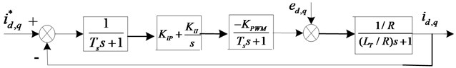
PMW rectifier has nonlinear characteristic. In view of avoiding the direct connection of IGBT, the drive delay of and the sampling delay of current inner loop, a first order inertial element with the small time constant is used to express the PWM rectifier, . In addition, the current inner loop with the amplitude limiting of current instruction, not only makes the constant current of PWM rectifier’s operation, but also protects the IGBT. The structure of current inner loop in PWM rectifier is shown in Fig. 1, in which, is the proportional gain of current inner loop, is the integral gain of current inner loop, is the equivalent gain of bridge circuit PWM, and the total inductance is .
The component of reactive current is set to zero: 0, which makes the PWM rectifier achieve unit power factor control. In the process of dynamic with the current closed-loop, has little change. When the output voltage of DC side is stable, is transformed from transient state to zero. In view of LCL filter’s resonance, the value of control system’s damping ratio should be larger, which can inhibit the resonance and is favor to the stability of control system. When the parameters of current regulator are satisfied with the steady state error and constant damping ratio , the reloading synchronous pulse delay will affect the steady state performance of PWM rectifier control system directly. The less the reloading synchronous pulse delay is, the better the stability of PWM rectifier is to inhibition of LCL filter’s resonance [19, 20]. Therefore, the control delay of current should be reduced as far as possible.
In the current inner loop system, PI regulator parameters are and . According the typical I type system tuning method design, the damping ratio 0.7,
Fig. 1the structure of current inner loop in PWM rectifier
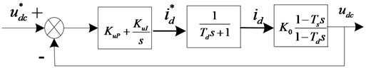
3.2.2. Outer loop control of voltage
The voltage outer loop can stabilize the output voltage of DC side. The transfer function of three phases PWM rectifier’s AC side output current and DC side output voltage is as follow:
where, , , , is the resistance of DC side load, is DC capacitance, is the AC voltage amplitude, and is the AC current amplitude.
The current loop is a second order system. When the value of input current is no error to track the instruction value, the order reduction for current loop is applied. The current loop is replaced by a first order inertial element . The construction of voltage outer loop is obtained as Fig. 2:
where, is the relevant function between the total inductance value and the proportional coefficient of PI regulator, .
The transfer function of voltage outer loop is as follow:
where, , is proportional gain of voltage outer loop, and is integral gain of voltage outer loop.
It is very important of the current regulator to the current inner-loop, which can achieve the better dynamic performance of current. In order to make the pole zero cancellation, the regulator of voltage outer loop should be satisfied with: . It is substituted into Eq. (3), the opened-loop transfer function of voltage outside-loop is obtained:
So, the closed-loop transfer function of voltage outer loop is as follow:
Because the inductance of control system is small, the time constant influences the dynamic property slightly and can be neglected. can be simplified:
When the current loop is designed, it is found that the digital control system has the time delays including IGBT drive, the current inner loop sampling and PWM signals dead time, which have great effect on the stability of PWM rectifier based on LCL filter. These delays of digital control system can be used to achieve the stabilized control on PWM rectifier based on LCL filter. Otherwise, the damping in fixed switching frequency control is favoring to be stable for the whole rectifier operation.
Fig. 2The diagram of voltage outer loop for PWM rectifier
The sampling time of PI regulator is adjusted to change the delay. The shorter the sampling time of the current feedback in converter side is, the better the stability of system is. However, the shorter sampling time needs the higher demand of microprocessor, which increases the cost. When PI regulator’s sampling is in half of LCL filter’s resonance period, the system can obtain good performance.
In the voltage outer loop system, as mentioned above, PI regulator parameters: . According the typical I type system tuning method design, the damping ratio 0.7 in Eq. (6), so the equation of is as follow:
4. Simulation and results analysis
The MATLAB/Simulink construct simulation platform is adopted to simulate the fixed switching frequency control strategy of three phase voltage PWM rectifier base on L filtering, as well as the undamped control strategy of three phase voltage PWM rectifier base on LCL filtering. The simulation results in different parameters are analyzed to verify the validity of the control strategy. The simulation model of the fixed switching frequency control strategy of PWM rectifier base on L filtering is shown in Fig. 3. The simulation model of the undamped control strategy of PWM rectifier base on LCL filtering is shown in Fig. 4.
4.1. The system simulation of higher DC voltage output
The simulation parameters are set as: voltage 380 V; DC voltage is 1000 V; the switching frequency is 5 kHz; the sampling frequency is 10 kHz. According to the design rule of filter, the suitable parameters are chosen as: the grid side inductance 0.4 mH, its internal resistance is 0.1 Ω; AC side filtering capacitance 20 µF; AC side inductance 0.8 mH, its internal resistance is 0.2 Ω. Normally, the resonance frequency of LCL filter is 2180 Hz, which meets with the design requirement. DC side capacitance 5000 µF, the load resistance = 100 Ω. Conveniently, the inductance of L filter is set as 1.2 mH, its internal resistance is 0.3 Ω; other parameters is same. The simulation results of PWM rectifier control system are shown as Fig. 5 to Fig. 11.
Fig. 3Simulink of the fixed switching frequency control strategy for PWM rectifier with L filter
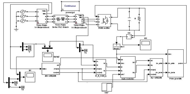
Fig. 4Simulink of the undamped control strategy for PWM rectifier with LCL filter
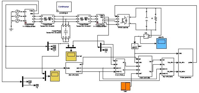
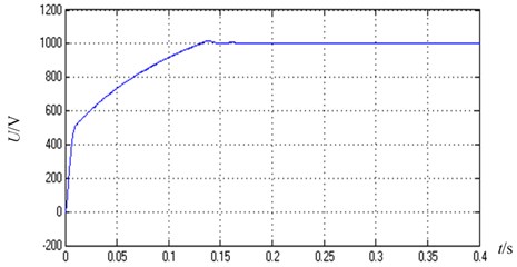
Fig. 5 is the output DC waveform of voltage for PWM rectifier with L filter. At first, the capacitance voltage of DC side is zero, then the value of voltage increases rapidly. This voltage incretion is slow after 0.01 s and the voltage arrives to the maximum value 1016.3 V at 0.138 s. After 0.18 s, the voltage achieves stable mostly. The DC output response of PWM rectifier is fast, its overshoot amount is in 2 %, and DC output is stable.
Fig. 5Output DC waveform of voltage for PWM rectifier with L filter
The amplification waveform of output DC voltage for PWM rectifier with L filter is shown in Fig. 6. This voltage has been stable after 0.2 s, but its ripple is big after amplification.
Fig. 6The amplification waveform of Output DC voltage for PWM rectifier with L filter
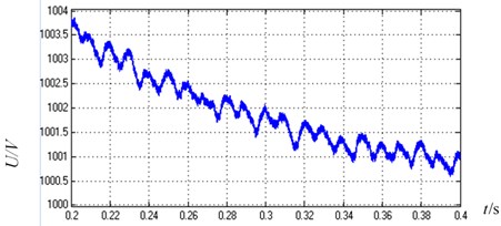
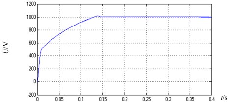
Fig. 7 is Output DC enlargement waveform of voltage for PWM rectifier with LCL filter. At beginning, the voltage increases rapidly, and this incretion of voltage is slow after 0.01 s. This voltage arrives to the maximum value 1016.2 V at 0.138 s and is stable mostly after 0.18 s. The DC output response of PWM rectifier is fast, its overshoot is amount to 2 %, and DC output is stable.
Fig. 7Output DC enlargement waveform of voltage for PWM rectifier with LCL filter
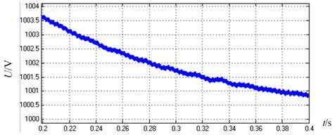
Similarly, the amplification waveform of Output DC voltage for PWM rectifier with LCL filter is shown in Fig. 8. After 0.2 s, this voltage becomes stable, its ripple is small after amplification and its precision is high. This system is stable and achieves better performance. With comparison and analysis between Fig. 6 and Fig. 8, it is obviously that the amplification waveform of output DC voltage for PWM rectifier with LCL filter has fewer ripples than that of output DC voltage for PWM rectifier with L filter. In PWM rectifier with LCL filter, DC voltage output precision is higher, its control effect is better.
Fig. 8The amplification waveform of output DC voltage for PWM rectifier with LCL filter
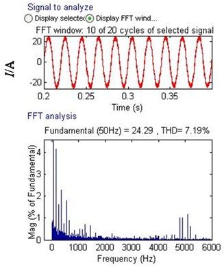
In Fig. 9, the current and current harmonic spectrum of A-phase on grid side for PWM rectifier with L filter is shown. The current of AC side is sinusoidal waveform, but it has some harmonic. Total harmonic distort (THD) is 7.19 %. The amplitude of higher harmonic around switching frequency 5 kHz can achieve 1.3 %. The THD of grid side current output is beyond 5 % of the standard of IEC.
Fig. 9Current and current harmonic spectrum of A-phase on grid side for PWM rectifier with L filter
Similarly, the current and current harmonic spectrum of A-phase on converter side for PWM rectifier with LCL filter is shown in Fig. 10. The current of AC side is similar to sinusoidal waveform, but it has much harmonic, Total harmonic distort (THD) is 26.76 %, the amplitude of higher harmonic around switching frequency 5 kHz is very high, even to 7.5 %. The THD of grid side current output is far beyond 5 % of the standard of IEC.
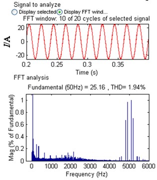
Fig. 11 is the current and current harmonic spectrum of A-phase on grid side for PWM rectifier with LCL filter. The current of grid side is sinusoidal waveform, it has little harmonic and system can operate stably, Total harmonic distort (THD) is only 1.94 %, the amplitude of higher harmonic around switching frequency 5 kHZ decreases sharply, the amplitude of higher harmonic is only 1 %. The THD of net side current output is far under 5 % of the standard of IEC.
With Comparison between Fig. 9 and Fig. 11, it is seen that the filtering effect of LCL filter is better than that of the L filter in PWM rectifier. Moreover, with comparison with Fig. 10 and Fig. 11, the control system with three phase voltage PWM rectifier based on LCL filter can operate stably, inhibit the resonance well and the amplitude of higher harmonic decreases sharply. This system achieves the expected control performance.
Fig. 10Current and current harmonic spectrum of A-phase on converter side for PWM rectifier with LCL filter
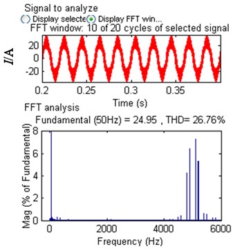
Fig. 11Current and current harmonic spectrum of A-phase on grid side for PWM rectifier with LCL filter
4.2. The system simulation of normal DC voltage output
When the undamped control strategy is designed, the parameters of PI regulator and the sampling time are considered for the effect on system stability. The simulation platform is built by to MATLAB/Simulink to verify the undamped control strategy of PWM rectifier based on LCL filter. The simulation parameters are set as follows: The effective value of line voltage is 380 V; the line frequency is 50 Hz; the capacitance of DC side is 5000 µF; resistive load is 100 Ω; DC voltage is 700 V; and switching frequency is 5 kHz. The appropriate parameters are chosen according with the result of filter’s design: the inductance of grid side is 0.8 mH, internal resistance is 0.1 Ω; the filtering capacitor of AC side is 12 µF; AC side inductance is 1.6 mH, internal resistance is 0.2 Ω.
Fig. 12Sampling time and current harmonic spectrum on grid side
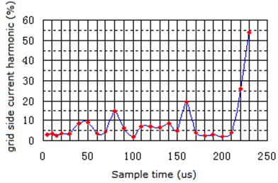
During the simulation process, the sampling time of PI Regulator is changed from 5 µs to 230 µs, the harmonic relation between the sampling time and grid side current is shown as Fig. 12. It is seen that, the shorter the sampling time is, the little the grid side current harmonic’s incretion tendency is, and the longer the sampling time is, the poorer the stability of system is. The sampling time is under a half of the resonance periodic time of LCL filtering so that the system obtains the better performance. However, in certain sampling time from Fig. 12, current harmonic of grid side has increased obviously, and the performance of the control system becomes poor, so the undamped control strategy will make the stability range become small.
In addition, when the sampling time is 200 µs (from Fig. 12), the system become stable and have the better effect of filtering, these simulation results are shown from Fig. 13 to Fig. 18.
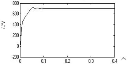
Fig. 13 is the output DC waveform of voltage for PWM rectifier with LCL filter. It can be seen that the voltage become stable after 0.09 s, the dynamic performance is very good, overshoot is under 5 %, and system achieves the expecting control effect.
Fig. 13Output DC waveform of voltage for PWM rectifier with LCL filter
The current of A-phase on converter side and voltage of A-phase on grid side is shown in Fig. 14, in which the stable current waveform is sinusoidal wave, but it has many current harmonics.
The waveforms of current and voltage in A-phase on grid side are shown in Fig. 15. The stable current waveform is sinusoidal wave, but the current harmonics have decreased obviously.
Fig. 14Current of A-phase on converter side and voltage of A-phase on grid side
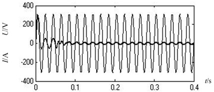
Fig. 15Current and voltage of A-phase on grid side
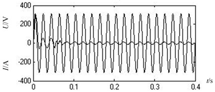
Fig. 16 is the current and current harmonic spectrum of A-phase on converter side of PWM rectifier base on LCL filter. The AC side current has many harmonics, Total Harmonic Distortion (THD) is 22.39 %, it has many higher harmonics when the switching frequency around 5 kHz, its amplitude is 9.79 %, which is far beyond the 5 % of IEC’s standard.
Fig. 16Current and current harmonic spectrum of A-phase on converter side
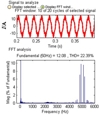
Fig. 17Current and current harmonic spectrum of A-phase on grid side
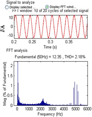
Fig. 17 is the current and current harmonic spectrum of A-phase on grid side of PWM rectifier based on LCL filter. The AC side current has many harmonics, Total Harmonic Distortion (THD) is only 2.18 %, the amplitude of higher harmonic is 1.18 %when the switching frequency around 5 kHz, which is far under the 5 % of IEC’s standard.
With Comparison among Fig. 14, Fig. 15, Fig. 16 and Fig. 17, it can be seen that the PWM rectifier based on LCL filter can work stability, the distortion rate of current waveform is low, the harmonic inhibiting is well, current higher harmonic on grid side has decreased obviously and system can achieve the expecting effect. Zhang Xianping and Lin Zixu and so on adopts the control method which virtual series resister, which can achieve the same control effect by using the filter which the total inductance is 8 mH.
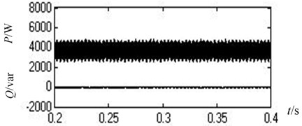
The waveforms of reactive power and active power are shown in Fig. 18. The reactive power is o, which achieves the operation with the unit power factor.
Fig. 18Reactive power and active power
5. Conclusions
In this paper, the undamped control strategy of PWM rectifier base on LCL filter is studied, and the control based on the fixed switching frequency is used to verify. The fixed switching frequency owns the closed-loop current control in grid side, which is not sensitive to the change of system parameters and reduces the filter inductance value. The time delay of system and the fixed switching frequency are used to control the damp. PI regulator’s sampling time is adjusted to achieve the system stability.
With comparison and analysis on PWM rectifier between the fixed switching frequency base on L filtering and the undamped control strategy based on LCL filtering, the simulation results show that: LCL filter has the better performance than L filter to the higher harmonic, decreases obviously the output DC voltage ripple of PWM rectifier and has higher precision. The undamped control strategy based on LCL filtering doesn’t produce the power loss, reduces the cost, and reduces sharply the filtering inductance, which is suitable to high power system. In additional, with the delay and damping of control system, the system can operate stability by selecting the suitable PI regulator, the harmonic content of grid side has been reduced sharply, and the resonance of LCL filter has been inhibited effectively.
References
-
Liserre M., Blaabjerg F., Hansen S. Design and control of an LCL-filter-based three-phase active rectifier. IEEE Transactions on Industry Applications, Vol. 41, Issue 5, 2005, p. 1281-1291.
-
Jalili Kamran, Bernet Steffen Design of LCL filters of active-front-end two-level voltage-source converters. IEEE Transactions on Industrial Electronics, Vol. 56, Issue 5, 2009, p. 1674-1689.
-
Wu W., Sun Y., Lin Z., et al. A new LCL-filter with in-series parallel resonant circuit for single-phase grid-tied inverter. IEEE Transactions on Industrial Electronics, Vol. 61, Issue 9, 2014, p. 4640-4644.
-
Xu J., Yang J., Ye J., et al. An LTCL filter for three-phase grid-connected converters. IEEE Transactions on Power Electronics, Vol. 29, Issue 8, 2014, p. 4322-4338.
-
Wu Jian, Xu Dianguo, He Na Research on LCL filter applied to shunt active power filter. Electric Power Automation Equipment, Vol. 27, Issue 1, 2007, p. 17-20.
-
Bierhoff Michael H., Friedrich Wilhelm Fuchs Active damping for three-phase PWM rectifiers with high-order line-side filters. IEEE Transactions on Industrial Electronics, Vol. 56, Issue 2, 2009, p. 371-379.
-
Liserre M., Dell Aquila A., Blaabjerg F. Stability improvements of an LCL-filter based three-phase active rectifier. Proceedings of the IEEE Power Electronics Specialist Conference, 2002, p. 1195-1201.
-
Liserre M., Dell’aquila A. A., Blaabjerg F. Genetic algorithm-based design of the active damping for an LCL-filter three-phase active rectifier. IEEE Transactions on Power Electronics, Vol. 19, Issue 1, 2004, p. 473-479.
-
Zhang Xianping, Lin Zixu, Li Yaxi, et al. A novel control strategy for PWM rectifier with LCL filter. Transactions of China Electrotechnical Society, Vol. 22, Issue 2, 2007, p. 74-77.
-
Hredzak B., Agelidis V. G., Jang M. A model predictive control system for a hybrid battery-ultracapacitor power source. IEEE Transactions on Power Electronics, Vol. 29, Issue 3, 2014, p. 1469-1479.
-
Kwak Sangshin, Park Jun Cheol Model-predictive direct power control with vector preselection technique for highly efficient active rectifiers. IEEE Transactions Industrial Informatics, Vol. 11, Issue 1, 2015, p. 44-52.
-
Tan G., Cao X., Wang C., et al. Instantaneous switching frequency suppression method for three-level PWM rectifier based on satisfactory optimization. Proceedings of the CSEE, Vol. 34, Issue 24, 2014, p. 4057-4067.
-
Yuan Q., Xia K. Current decoupling control for the three-level PWM rectifier with a low switching frequency. Journal of Electrical Engineering and Technology, Vol. 10, Issue 1, 2015, p. 280-287.
-
Zhang H., Yu R. W., Yan Z. F., et al. Design of robust direct current control for three-level pulse-width modulated rectifier. Journal of Computational and Theoretical Nanoscience, Vol. 13, Issue 5, 2016, p. 3151-3160.
-
Giacomini J., Michels L., Pinheiro H. Active damping scheme for leakage current reduction in transformerless three-phase grid-connected PV inverters. IEEE Transactions on Power Electronics, 2017, https://doi.org/10.1109/TPEL.2017.2711785.
-
Zhang N., Tang H., Yao C. A systematic method for designing a PR controller and active damping of the LCL filter for single-phase grid-connected PV inverters. Energies, Vol. 7, Issue 6, 2014, p. 3934-3954.
-
Torbati Eskandari H., Khaburi D. A., Torbati Eskandari V. Control of three phase PWM rectifier using virtual flux-based predictive direct power control and SVM under harmonic conditions. International Journal of Numerical Modelling Electronic Networks, Vol. 29, Issue 2, 2016, p. 205-221.
-
Fekik A., Denoun H., Zaouia M., et al. Improvement of the performances of the direct power control using space vector modulation of three phases PWM-rectifier. International Journal of Control Theory and Applications, Vol. 10, Issue 30, 2017, p. 133-145.
-
Nussbaumer T., Heldwein M. L., Guanghai Gong, Round S. D., Kolar J. W. Comparison of prediction techniques to compensate time delays caused by digital control of a three-phase buck-type PWM rectifier system. IEEE Transactions on Industrial Electronics, Vol. 55, Issue 2, 2008, p. 791-799.
-
Xiao X., Zhang Y., Wang J., et al. An improved model predictive control scheme for the PWM rectifier-inverter system based on power-balancing mechanism. IEEE Transactions on Industrial Electronics, Vol. 63, Issue 8, 2016, p. 5197-5208.
About this article

This work is supported by the National Natural Science Foundation of China (U1404512 and 61473115) and the Project of Luoyang Science and Technology Development Plan (1401017A).
