Abstract
In the paper, the numerical simulation is conducted on the motor electromagnetic force firstly. Radial force waves of the motor are the main reason for causing electromagnetic vibration and noise. Then, electromagnetic forces are mapped into a structural model for computing electromagnetic vibration. Computational results are compared with experimental results, so the correctness of the computational model is verified. Then, electromagnetic noises are computed according to the vibration data of the motor. Electromagnetic noises of the motor are axis-symmetric in plane and plane . In plane , the electromagnetic noise of the motor is skew-symmetric relative to a 45° angle. In plane and plane , the noise is caused by the vibration of the end cap, while noise in plane is caused by electromagnetic radial forces. In addition, the motor electromagnetic noise has an obvious directivity. The motor also has obvious peak noises at 300 Hz, 400 Hz, 500 Hz, 600 Hz, 900 Hz, 1200 Hz, 1500 Hz and 1800 Hz. Peak noises are corresponding to 6th, 8th, 10th, 12th, 18th, 24, 30th and 36th orders of the motor. Finally, modal participation factors of the motor within the analyzed frequency are computed. Results showed that modals at the 3rd, 5th, 12th and 15th orders of the motor have most obvious impacts on electromagnetic noises. In particular, the 3rd order modal shape obviously affects electromagnetic noises. The electromagnetic noise is reduced by applying reinforced bars and damping layer to these key modal shapes, especially the peak noise. The total noise of the original structure is 58 dB, while the total noise of the improved structure is 52.3 dB. Obviously, the total noise is reduced by 9.8 %.
1. Introduction
Regarding many advantages in wide high-efficiency regions, high torque density and compact structures, permanent magnet synchronous motors have become one of main driven motors in vehicles. Due to high torque and speed regulation characteristics as well as small-size and light-weight design for motors, electromagnetic force amplitudes of motors are always large, rigidity of motor structures is poor, serious electromagnetic vibration and noise can be caused easily, and riding comfort will be affected. Motor noises are mainly composed of three parts as follows. (1) Electromagnetic noises: Air gap magnetic force waves act between a stator and a rotor, which will cause unbalanced electromagnetic force waves with time and space. Therefore, the stator generates vibration and then the vibration is transmitted to a frame on the motor surface. Serious resonances will be caused especially when the frequency of these force waves approaches natural frequencies of mechanical parts of the motor. (2) Mechanical noises: It is caused by operation of mechanical parts, bearings or brushes, etc. (3) Aerodynamic noises: It is mainly caused by aerodynamic forces in ventilation components of the motor. Regarding performance requirements of the motor, slide bearings with high-damp and low-noise, and counter-rotation components adopted by the motor have strict dynamic balance requirements. Mechanical noises and aerodynamic noises of motors are not obvious. Mainly the vibration caused by electromagnetic noises is obvious. Therefore, when a motor is designed, electromagnetic performance indexes of the motor should be assessed. Electromagnetic vibration and noise characteristics of the motor should also be highlighted [1-3]. Electromagnetic vibration and noise of a motor is mainly caused by radial force waves.
Electromagnetic vibration and noise of motors is a multi-physics field problem, involving multiple fields including electromagnetism, dynamics, structure and acoustic field. Electromagnetic noises of motors are mainly studied by analytical method, finite element method and experimental test [4-9]. Islam [10] proposed a method, where coupling analysis between electromagnetic and vibration was conducted by finite element software, and then motor noises could be predicted according to response superposition theories. Torregrossa [11] proposed a field reconstruction method to conduct analytical computation for motor noises. Verez [12] studied impacts of PWM sine wave power supply on noises of motors. Based on multi-physics field platform in ANSYS, Zheng [13] studied electromagnetic vibration and noise characteristics of a permanent magnet synchronous motor and analyzed main sources which might cause serious electromagnetic noises from two aspects including electromagnetic force and motor structures. Dai [14] listed dangerous electromagnetic force waves which might cause electromagnetic vibration and noise of an asynchronous motor. The finite element simulation was also adopted to obtain gap flux densities at key working points of the motor. The space-time harmonic analysis on flux density harmonic waves was conducted in order to determine amplitudes and frequencies of dangerous electromagnetic force waves. Based on electromagnetic field analysis theories, Luo [15] conducted finite element simulation of radial force waves of a permanent magnet brush-less motor, in order to conduct dynamic modeling and simulation research on the motor stator. Li [16] applied electromagnetic field theories to make qualitative analysis on mechanisms and characteristics of radial waves which were major reason for electromagnetic vibration and noise. An analyzed method for motor vibration and noise was proposed based on the modal superposition method according to characteristics of the radial force waves. In order to study high-frequency electromagnetic noises of electric vehicles, Fang [17] took a power assembly of the electric vehicle as the studied object and established a finite element model of the power assembly based on comprehensive consideration for electromagnetic force waves in radial and tangential directions of the motor. Zuo [18] designed an electromagnetic noise test method for a hub motor under torques and tested electromagnetic noises of the hub motor with different rotation speeds and torques. Xing [19] applied MAXWELL to establish a finite element model, computed the radial electromagnetic force, input time-domain results into MATLAB for frequency spectrum analysis. The frequency-domain data of electromagnetic force waves was obtained in order to study the electromagnetic noise. However, in the published researches, electromagnetic noises of motors were not reduced by taking some measures. Additionally, numerical simulation and experimental test were not combined for validation.
Regarding improvement of electromagnetic vibration and noise of motors, Zhao [20] conducted experimental researches on reasons of motor noises, determined the noise sources and found that structural intensity improvement could reduce the noise. He [21] conducted comprehensive and systematic test on relatively serious motor vibration and noises, finding that the motor electromagnetic schemes had design defects, and reducing noises through modifying the connection type. Zhang [22] applied CFD technologies to conduct three- dimensional unsteady numerical simulation of aerodynamic characteristics of an AC generator. Based on the numerical simulation, with low noise and high flow rate as the optimization goals, aerodynamic noise optimization and noise reduction researches were conducted on radial grating distribution angles of the front end cap of the AC generator. However, they did not obtain obvious noise reduction effects in the full frequency band through the optimization measures.
In the paper, numerical computation is conducted on the motor electromagnetic force firstly. Then, electromagnetic forces are mapped into a structural model for computing electromagnetic vibration. Computational results are compared with experimental results, so correctness of the computational model is verified. In the way, electromagnetic noises are computed according to the vibration data of the motor. Some measures are finally adopted to reduce electromagnetic noises of the motor, where noise reduction effects are very obvious.
2. Numerical computation and experimental validation of electromagnetic forces
2.1. Numerical computation of electromagnetic forces of motors
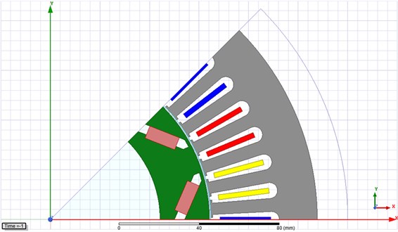
In the paper, the Pro-engineer software is used to establish a motor model. Before it is input into ANSYS, the CAD model is simplified, and some secondary structures are neglected, so mesh division and computation will become more convenient. For example, parts such as gaskets, velometers, detailed chamfers and drawing dies are neglected. Fig. 1 shows the established geometric model of the motor. The motor contains 24 slots and 12 poles. The rated rotation speed is 3000 rpm. Other related parameters are shown in Table 1.
Table 1Basic parameters of permanent magnet synchronous motors
Parameters | Value | Parameters | Value |
Outer diameter of stator / mm | 120 | Rated torque / N.m | 10 |
Inner diameter of stator / mm | 80 | Rated rotation speed / rpm | 3000 |
Number of stator slots | 24 | Number of pole pairs | 12 |
Slot depth / mm | 14 | Air gap length / mm | 1 |
Fig. 1Geometric model of permanent magnet synchronous motors
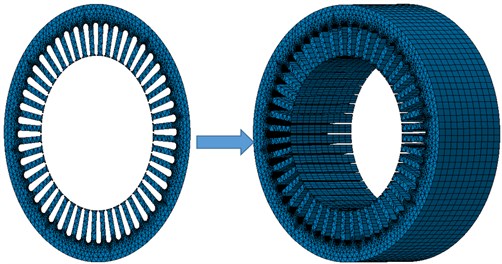
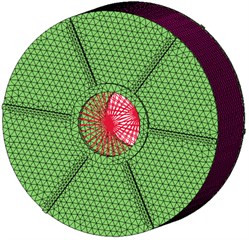
During electromagnetic analysis on a permanent magnet synchronous motor, a finite element model of the motor should be established firstly. Electromagnetic analysis on the motor mainly studied characteristics of gap flux density acting between the motor stator and the rotor, so the finite element model of the stator and rotor should be established during modeling, and some secondary parts should be neglected. The electromagnetic simulation analysis software Ansoft is used to establish a two-dimensional finite element analysis model of the motor and then a three-dimensional model is obtained after stretching, as shown in Fig. 2. Under the condition of steady and symmetric loads, the fundamental wave magnetic potentials of the motor stator and rotor are rotated under a synchronous speed. They can be deemed to be relatively stationary. Therefore, the electromagnetic field at any instant state can be deemed as a constant magnetic field during analysis. ANSYS is used to conduct finite element analysis. The element type is a default three-dimensional solid element. Material properties such as elasticity modulus, Poisson’s ratio and density of each part are defined. The motor is an assembled body, so related contact types should be defined. Then, mesh division of the complete model is carried out. Mesh division has obvious impacts on computational results. In general, some meshes must had high quality. Nodes should be sufficient, and relative element distribution should be rational during division of the finite element model. Regarding the stator, density is 7700 kg/m3; elasticity modulus is 2.05e11Pa; Poisson’s ratio is 0.27.
Fig. 2Finite element model of electromagnetic forces of motors
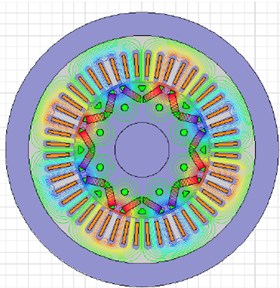
According to the given structural parameters of the motor, a finite element simulation model of the motor is established. Through simulation computation, contours of magnetic force distribution and flux density in the motor at the time 0.04 s are obtained, as shown in Fig. 3. Obviously, the magnetic pole directly faces the stator tooth; nearly all the magnetic force lines enter the stator tooth along the axial direction; the tooth flux density is high; radial electromagnetic force density is high and nearly distributed on the complete tooth uniformly, which will cause radial telescopic vibration of the stator tooth. At the positions between poles, which directly faces the stator tooth, the tangential components of magnetic force lines are large; at the position, radial electromagnetic forces borne by the stator tooth have relatively small density, which will cause uneven radial force on the stator tooth as well as sway and vibration of the tooth. Therefore, radial force waves of the motor are the main reason for causing electromagnetic vibration and noise.
Fig. 3Contours of flux density and magnetic force lines of motors
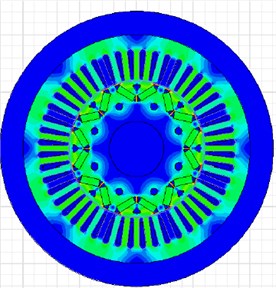
a) Flux density of motors
b) Magnetic force lines of motors
The time-frequency spectrum of radial electromagnetic force density of the motor under 3000 rpm is shown in Fig. 4. It is shown in Fig. 4(a) that the time-domain electromagnetic force density presents an obvious periodicity, where the maximum electromagnetic force density is 6e5N/m2. The electromagnetic force density under time-domain is processed by Fourier transform, so results of the frequency domain are obtained, as shown in Fig. 4(b). It is shown in the figure that the frequency-domain electromagnetic force density has many peak points, where peaks are especially obvious at 50 Hz, 900 Hz, 1200 Hz and 5800 Hz, and specific values are 112 dB, 110 dB, 100 dB and 65 dB, respectively. Peak frequencies of electromagnetic forces are caused by that the motor has obvious orders as a rotational body. In addition, the electromagnetic force spectrum of the motor is mainly concentrated within 4000 Hz.
Fig. 4Time-domain and frequency-domain electromagnetic force density
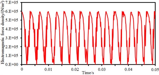
a) Time-domain electromagnetic force density
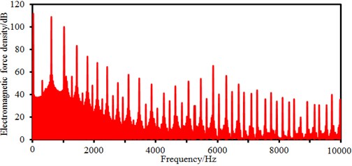
b) Frequency-domain electromagnetic force density
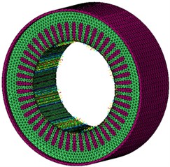
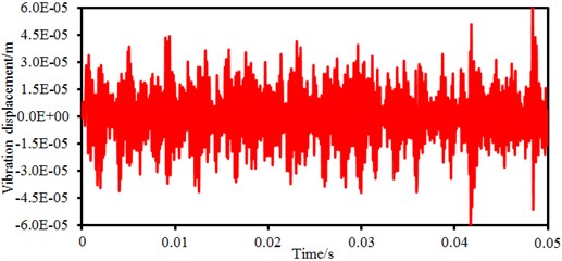
Electromagnetic vibration of the permanent magnet synchronous motor can be studied by ANSYS transient dynamics analysis. Radial electromagnetic forces of each tooth varying with time can be obtained through electromagnetic analysis. As an excitation source of dynamic simulation, it is loaded into a three-dimensional finite element model of the motor, as shown in Fig. 5. It is shown in Fig. 5 that the finite element model of the structure contains end cap and cover of the motor. In this way, electromagnetic vibration of the motor under radial electromagnetic forces can be computed, as shown in Fig. 6. It is shown in the figure that the motor displacement fluctuates seriously around 0, but fails to show an obvious periodicity like the electromagnetic force density. The motor vibration displacement has the maximum vibration amplitude around 0.05 s, where the maximum value is 6e-5m. Large vibration responses do not appear in low-order harmonic waves, while they are at high orders, namely large time points. In vibration responses, the vibration amplitude is in direct proportion to excitation force wave amplitudes, while large amplitudes of low-order harmonic waves can easily cause vibration. However, when the frequency of excitation force waves under specific orders approach natural frequencies of corresponding modes, even very small force wave amplitudes can lead to large vibration responses.
Fig. 5Finite element model of the structural vibration of motors
a)
b)
Fig. 6Electromagnetic vibration displacement of permanent magnet synchronous motors
2.2. Experimental verification of the electromagnetic vibration of motors
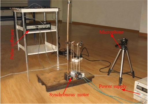
Numerical computation models of vibration characteristics of motors are very complicated and can be obtained indirectly through electromagnetic force density. Therefore, it is necessary to verify correctness of computational results by experimental test. Experimental equipment includes QDAC signal generation modules of LMS, power amplifiers and exciters, such as an acceleration sensor, a force sensor, an LMS signal amplification and intelligent collection system, and LMS vibration analysis software Test.lab. Vibration characteristics within 0-10000 Hz are mainly studied in experiments. The motor is powered and started working under a no-load state. Signal sampling frequency is 25000 Hz; the sensor is surrounded on the outer surface of the stator near the end part; motor vibration signals tested by the sensor are input into Test.lab for analysis and processing. In order to avoid interference of loads on electromagnetic vibration of the motor and ensure accurate test on the motor stator surface, the permanent magnet synchronous motor in the paper is hung on a rigid support by a soft rubber band, as shown in Fig. 7.
Fig. 7Experimental test on vibration characteristics of motors
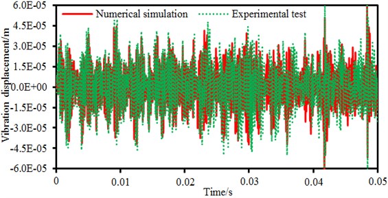
Experimental results of the vibration displacement is compared with numerical simulation results, as shown in Fig. 8. It is shown in the figure that changing trends between experimental and numerical simulation results are consistent while peak points of the vibration displacement are completely consistent. Results of the experimental test are slightly more than those of numerical simulation because the vibration displacement of experimental test not only contains the electromagnetic vibration, mechanical vibration and aerodynamic vibration, but also contains tangential electromagnetic forces. Numerical simulation results only involve vibration results under the radial electromagnetic force. Despite of the slight difference in values, the numerical simulation can still replace experimental test.
Fig. 8Comparison of the electromagnetic vibration between experiment and simulation
3. Numerical computation and experimental verification of electromagnetic noises
3.1. Numerical computation of electromagnetic noises
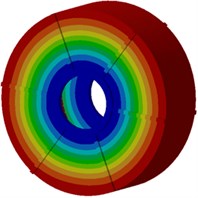
Next, modal participation factors will be used to recognize modals which affect the motor electromagnetic noise obviously, in order to improve the structure and reduce the noise. Therefore, the finite element model is used to compute modals of the motor, as shown in Fig. 9. It is shown in the figure that modals of the motor at each order present an obvious symmetry while positions with serious vibration are located at the radial cover surface of the motor as electromagnetic forces of the motor are also distributed symmetrically in the radial direction, and positions with serious vibration are under different rotation angles of the motor. With the increased analysis order, multiple wave nodes are at the motor end cap such as 7th and 8th modal shapes.
Fig. 9Modal shapes of motor structures at top 8 orders
a) First order
b) Second order
c) Third order
d) Fourth order
e) Fifth order
f) Sixth order
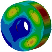
g) Seventh order
h) Eighth order
The FEM/AML method is used to compute radiation noises of the motor. The motor AML model should be established at first. During establishment of the AML model, the mesh size should be more than that of the finite element meshes. In general, the characteristic size of the AML model should satisfy the following requirements:
where: is the velocity of sound waves, which is generally set to be 340 m/s; is the maximum frequency, equal to 10000 Hz; is the multiple of the sound wave length relative to the element mesh size, where larger leads to higher accuracy of computational results and generally 6, and is 8 in the paper. Therefore, in the paper, the element size is 4 mm during division of the AML meshes. During mesh division, meshes should also be simplified in combination with the specific finite element model.
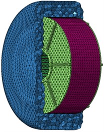
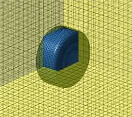
The vibration displacement obtained by harmonic response analysis is taken as the boundary condition of acoustic analysis. Acoustic meshes and structural meshes of the motor are inconsistent in element size, element density and node coordinates, so the input vibration displacement should be transferred, and thus corresponding relations between vibration data and meshes could be established. The AML model has 13250 nodes and 9816 elements, as shown in Fig. 10. In the computation, it is assumed that the motor is located in free space and free of reflection face structures, and the fluid medium is air. In the end, some basic acoustic analysis items are defined, so the motor sound field responses can be computed.
Fig. 10AML model of electromagnetic noises of permanent magnet synchronous motors
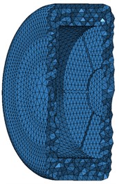
a)
b)
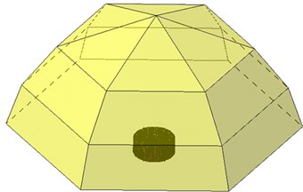
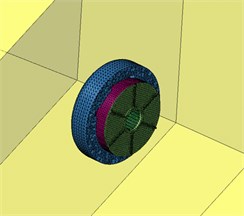
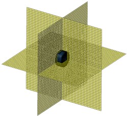
When sound waves are propagated in the medium, the medium will absorb the sound waves, so sound waves will be attenuated with the increased propagation distance. Therefore, during studying a small-power motor, the motor can be processed as a point sound source within the distance of 1.5 m away from the motor. At this moment, radiation attenuation of the noise is very small and can be neglected. Based on these theories, a semi-spherical field point with the center radius of 1 m is selected. In this way, the situations will be consistent with subsequent experimental test, as shown in Fig. 11. In addition, in order to observe sound field distribution of the motor in , and directions, field point models of three planes are established, as shown in Fig. 12.
Fig. 11Semi-spherical field point meshes of permanent magnet synchronous motors
a)
b)
Fig. 12Panel field point meshes of permanent magnet synchronous motors
a)
b)
Sound pressure levels of electromagnetic noises of the motor are extracted, as shown in Fig. 13. It is shown in the figure that when the analyzed frequency is lower than 1000 Hz, the sound pressure level gradually increased with the analyzed frequency and reached an obvious peak value. When the analyzed frequency is within 1000 Hz-3000 Hz, the sound pressure level gradually decreased with the analyzed frequency. Within 3000 Hz-10000 Hz, the sound pressure level reaches a stable value 35 dB, and obvious peak noises are only at frequency points of some orders. Regarding a rotational body, there are obvious rotation orders. According to Eq. (2), we can find that the first order of motors is 50 Hz, so peak noises which are not very obvious on the sound pressure level curve. As well, the motor also has obvious peak noises at 300 Hz, 400 Hz, 500 Hz, 600 HZ, 900 Hz, 1200 Hz, 1500 Hz and 1800 Hz, where they are corresponding to 6th, 8th, 10th, 12th, 18th, 24th, 30th and 36th orders of the motor. The motor has not order frequencies at some frequency points, but peak noises are still on sound pressure level curves because of resonance of the motor structure. According to Eq. (3), the total sound pressure level of electromagnetic noises can be computed, where the value is 58 dB.
Through FFT, frequency spectrum results under the constant rotation speed can be obtained. Based on order analysis theories, the relations between order and rotational speed can generally be expressed as follows:
where: is signal frequency (Hz), is the order, and is a referential axis rotation speed (r/min). Obviously, direct correspondence relations are between order and rotational speed. Essentially, order analysis is a signal processing method, where signals with equal time intervals are converted into signals with equal angle intervals, and then frequency spectrum analysis is conducted to the signals:
where: is the sound pressure level under the th frequency; is the amount of frequency points. is the total sound pressure level.
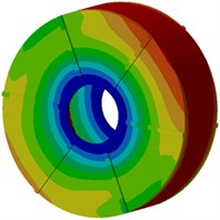
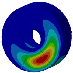
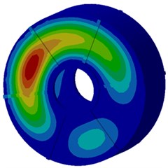
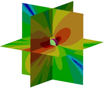
Sound pressure contours of electromagnetic noises are extracted, as shown in Fig. 14. It is shown in Fig. 14 that the electromagnetic noise contour of the motor presents an obvious symmetry, where electromagnetic noises of the motor are axis-symmetric in plane and plane . In plane , the electromagnetic noise of the motor is skew-symmetric relative to a 45° angle. In plane and plane , the noise is generated from vibration of the end cap, while noises in plane are caused by electromagnetic radial force. Obviously, the electromagnetic noise has an obvious directivity.
Fig. 13Sound pressure levels of electromagnetic noises of motors
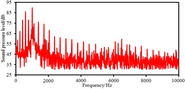
Fig. 14Sound pressure contours of electromagnetic noises of motors

a)
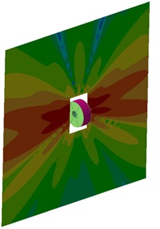
b)
3.2. Experimental verification of electromagnetic noises of motors
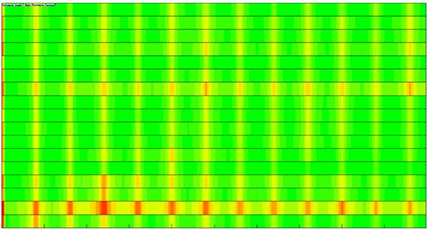
In order to verify the correctness of the method proposed in the paper, experimental test on noises is conducted on the motor. The experiment is carried out at 3000 rpm and the average background noise is 66 dB. The perpendicular projection center of the motor on the frame is taken as the spherical point. Observation points are located on the semi-spherical surface with radius of 1 m. Experimental results are revised, and a sound level meter is used to test A-weighting sound pressure levels of each observation point. Frequency of 20 kHz is adopted for each microphone. Fig. 15 shows chromatogram which is the motor noise with the rotational speed at 2 observation points. It is shown in Fig. 13 that main orders of the motor electromagnetic noise are 6th, 8th, 10th, 12th, 18th, 24th, 30th and 36th orders, etc. The result is consistent with the simulation conditions, verifying the correctness of computational results in the paper.
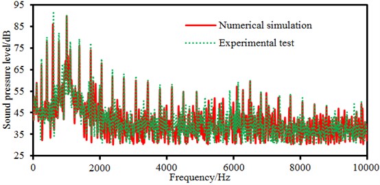
Sound pressures of observation points obtained in the experimental test are further extracted and compared with the numerical simulation results, as shown in Fig. 16. It is shown in the figure that each peak noise is completely consistent between experimental and numerical simulation results. However, peak noises in experimental test are more obvious because radiation noises in experimental test not only contains electromagnetic noises, mechanical noises and aerodynamic noises, but also contains electromagnetic noises caused by tangential electromagnetic forces. Numerical results only involve electromagnetic noises under radial electromagnetic forces. Despite of the slight differences in values, the numerical simulation can still replace experimental test.
Fig. 15Chromatogram of noise test on permanent magnet synchronous motors
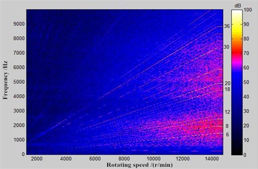
a) Noise observation point 1
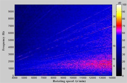
b) Noise observation point 2
Fig. 16Comparison of electromagnetic noises between experiment and simulation
4. Optimization of electromagnetic noises of motors
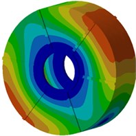
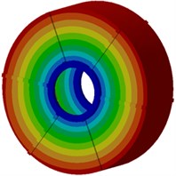
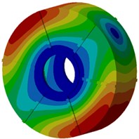
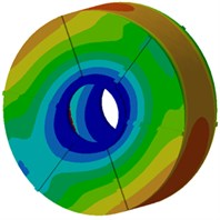
In order to recognize the modal shape which makes largest contributions to the motor electromagnetic noise, modal participation factors of the motor within the analyzed frequency are computed, as shown in Fig. 17. It is shown in Fig. 17 that modals at the 3rd, 5th, 12th and 15th orders of the motor have most obvious impacts on electromagnetic noises within the whole analysis frequency band. In particular, the 3rd order modal shape obviously affects electromagnetic noises in the whole frequency band. Modal shapes of these 4 orders are extracted, as shown in Fig. 18. It is shown in Fig. 18 that modal shapes of the 3rd and 5rd orders mainly reflect radial cover vibration; modal shapes of the 12th and 15th orders mainly reflect the vibration of end caps. Therefore, the motor cover structure must be improved.
Fig. 17Modal participation factors of electromagnetic noises of motors
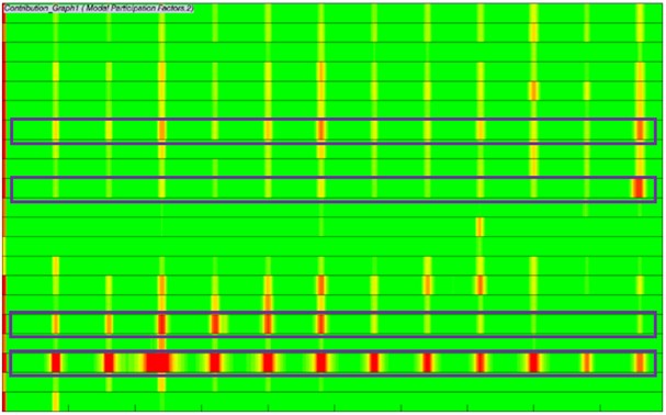
Fig. 18Key participant modal shapes of permanent magnet synchronous motors
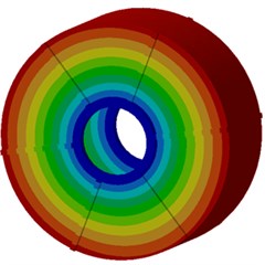
a) Third order
b) Fifth order
c) Twelfth order
d) Fifteenth order
Regarding the motor end cap, it is feasible to increase the width of reinforced bars and add a damping layer. Regarding the radial cover, a ring of damping layer and circumferential reinforced bars can be added, as shown in Fig. 19(b). Vibration energy can be effectively attenuated by the damping, where kinetic energy can be transformed into heat energy, so the vibration can be attenuated. The damping layer thickness is changed from 2 mm to 6 mm, and the step is 2 mm. Therefore, there are three kinds of improved motor models.
Electromagnetic noises of three improved motors are re-computed and compared with the original results, as shown in Fig. 20.
Fig. 19Improvement scheme for electromagnetic noises of motors
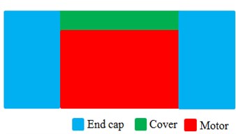
a) Original structure
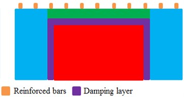
b) Improved structure
Fig. 20Comparison of electromagnetic noises between original and optimized results
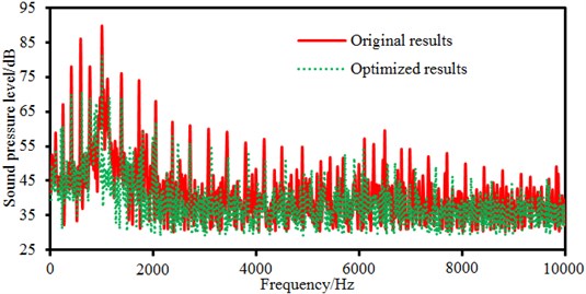
a) Damping layer thickness is 2 mm

b) Damping layer thickness is 4 mm
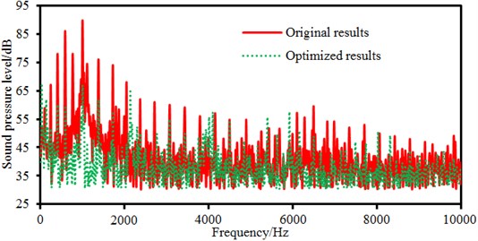
c) Damping layer thickness is 6 mm
It is shown in Fig. 20 that the motor electromagnetic noise is reduced in most frequency bands, especially the peak noise. Some peak frequency points between the improved structure and the original structure are consistent, but they are different at some peak points. In the paper, the structural improvement is only conducted on the motor cover, and structures of the stator and rotor in the motor are not changed, so peak noises caused by electromagnetic forces will not change obviously. Changes of the motor cover structure will cause modal changes of the structure, so some peak noise points are different.
In order to observe the improved effects, the total sound pressure level of each model is computed, as shown in Fig. 21. The total sound pressure level of the original structure is 58.0 dB; the total sound pressure level of the improved motor with 2 mm damping layer is 55.1 dB; the total sound pressure level of the improved motor with 4 mm damping layer is 53.5 dB; the total sound pressure level of the improved motor with 6 mm damping layer is 52.3 dB. Therefore, increasing the thickness of the damping layer can reduce the total sound pressure level of the motor. However, the thickness of the damping layer cannot always be increased because the assembly between the end cap and motor should be considered. If the thickness of the damping layer is too large, it is difficult to install the cover on the motor. As a result, we consider selecting the thickness of the damping layer as 6 mm. For the motor with 6 mm damping layer, the total noise is reduced by 9.8 %.
As well, modal participation factors of the improved motor with 6 mm damping layer are extracted, as shown in Fig. 22.
Fig. 21Total sound pressure level of the improved motor with different damping layer
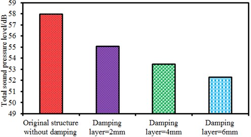
Fig. 22Modal participation factors of electromagnetic noises of motors
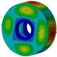
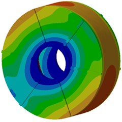
Compared with Fig. 17, modal contributions of each order of the improved motor are not very obvious. Instead, they are relatively uniform. The 2nd order modal shape makes the most obvious contributions. Compared with the original structure, contributions made by the 3rd order modal shape are also reduced. In order to further verify noise reduction effects, a contour of electromagnetic noises after optimization is extracted, as shown in Fig. 23. Obviously, compared with the original structure, the electromagnetic noise of the improved motor is reduced in each plane, and the noise directivity does not change. The analyzed results fully verify validity of the noise reduction measures proposed in the paper.
Fig. 23Sound pressure contours of electromagnetic noises of motors
a) Original results
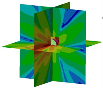
b) Optimization results
5. Conclusions
In the paper, the numerical computation is conducted on the electromagnetic force firstly. Then, electromagnetic forces are mapped into a structural model for computing electromagnetic vibration. The computational results are compared with experimental results, so the correctness of the numerical model is verified. Then, electromagnetic noises are computed according to the vibration data of the motor. Finally, some improved measures are adopted to improve electromagnetic noises of the motor, where noise reduction effects are very obvious. Therefore, the detailed conclusions can be obtained.
1) In the magnetic pole directly faced the stator tooth, radial electromagnetic force density is high and nearly distributed on the complete tooth uniformly, which will cause radial telescopic vibration of the stator tooth. At the positions between poles, which directly faces the stator tooth, the tangential components of magnetic force lines are large. At the position, radial electromagnetic forces borne by the stator tooth have relatively small density, which will cause uneven radial forces on the stator tooth as well as sway and vibration of the tooth. Therefore, radial force waves of the motor are the main reason for causing electromagnetic vibration and noise.
2) The motor has obvious peak noises at 300 Hz, 400 Hz, 500 Hz, 600 HZ, 900 Hz, 1200 Hz, 1500 Hz and 1800 Hz, where they are corresponding to 6th, 8th, 10th, 12th, 18th, 24, 30th and 36th orders of the motor. The motor has not order frequencies at some frequency points, but peak noises are still on the sound pressure level curve because of resonance of the motor structure.
3) Electromagnetic noises of the motor are axis-symmetric in plane and plane . In plane , the electromagnetic noise of the motor is skew-symmetric relative to a 45° angle. In plane and plane , the noise is caused by the vibration of the end cap, while noises in plane are caused by electromagnetic radial forces. Obviously, the motor electromagnetic noise has an obvious directivity.
4) Modal participation factors of the motor within the analyzed frequency are computed. Results show that modals at the 3rd, 5th, 12th and 15th orders of the motor have most obvious impacts on electromagnetic noises. In particular, the 3rd order modal shape obviously affects electromagnetic noises. The electromagnetic noise is reduced by applying reinforced bars and damping layer to these key modal shapes, especially the peak noise. The total noise of the original structure is 58 dB while the total noise of the improved structure is 52.3 dB. Obviously, the total noise is reduced by 9.8 %.
References
-
Sun T., Kim J. M., Lee G. H., et al. Effect of pole and slot combination on noise and vibration in permanent magnet synchronous motor. IEEE Transactions on Magnetics, Vol. 47, Issue 5, 2011, p. 1038-1041.
-
Yang H. Y., Lim Y. C., Kim H. C. Acoustic noise/vibration reduction of a single-phase SRM using skewed stator and rotor. IEEE Transactions on Industrial Electronics, Vol. 60, Issue 10, 2013, p. 4292-4300.
-
Dos Santos F. L. M., Anthonis J., Naclerio F., et al. Multiphysics NVH modeling: Simulation of a switched reluctance motor for an electric vehicle. IEEE Transactions on Industrial Electronics, Vol. 61, Issue 1, 2014, p. 469-476.
-
Hur J., Reu J. W., Kim B., et al. Vibration reduction of IPM-type BLDC motor using negative third harmonic elimination method of air-gap flux density. IEEE Transactions on Industry Applications, Vol. 47, Issue 3, 2011, p. 1300-1309.
-
Kim D. J., Kim H. J., Hong J. P., et al. Estimation of acoustic noise and vibration in an induction machine considering rotor eccentricity. IEEE Transactions on Magnetics, Vol. 50, Issue 2, 2014, p. 857-860.
-
Park S., Kim W., Kim S. I. A numerical prediction model for vibration and noise of axial flux motors. IEEE Transactions on Industrial Electronics, Vol. 61, Issue 10, 2014, p. 5757-5762.
-
Pompermaier C., Kalluf K., Zambonetti A., et al. Small linear PM oscillatory motor: Magnetic circuit modeling corrected by axisymmetric 2-D FEM and experimental characterization. IEEE Transactions on Industrial Electronics, Vol. 59, Issue 3, 2012, p. 1389-1396.
-
Chen N., Ho S. L., Fu W. N. Optimization of permanent magnet surface shapes of electric motors for minimization of cogging torque using FEM. IEEE Transactions on Magnetics, Vol. 46, Issue 6, 2010, p. 2478-2481.
-
Binojkumar A. C., Prasad J. S. S., Narayanan G. Experimental investigation on the effect of advanced bus-clamping pulsewidth modulation on motor acoustic noise. IEEE Transactions on Industrial Electronics, Vol. 60, Issue 2, 2013, p. 433-439.
-
Islam M. S., Islam R., Sebastian T. Noise and vibration characteristics of permanent-magnet synchronous motors using electromagnetic and structural analyses. IEEE Transactions on Industry Applications, Vol. 50, Issue 5, 2014, p. 3214-3222.
-
Torregrossa D., Khoobroo A., Fahimi B. Prediction of acoustic noise and torque pulsation in PM synchronous machines with static eccentricity and partial demagnetization using field reconstruction method. IEEE Transactions on Industrial Electronics, Vol. 59, Issue 2, 2012, p. 934-944.
-
Verez G., Barakat G., Amara Y., et al. Impact of pole and slot combination on vibrations and noise of electromagnetic origins in permanent magnet synchronous motors. IEEE Transactions on Magnetics, Vol. 51, Issue 3, 2015, p. 1-4.
-
Zheng J., Dai Y., Shi J. Electromagnetic noise characteristics of permanent magnet synchronous motor applied in electric vehicle. Transactions of China Electrotechnical Society, Vol. 31, Issue 1, 2016, p. 53-59.
-
Dai Y., Cui S., Zhang Q. Analysis on electromagnetic vibration/noise of induction motors for EV drives. Proceedings of the Chinese Society of Electrical Engineering, Vol. 32, Issue 33, 2012, p. 89-97.
-
Zuo S. G., He L. C., Wei H., Wen Q. H. Dynamic analysis and experimental research on stator vibration of BLDC motor. Journal of Vibration and Shock, Vol. 31, Issue 10, 2012, p. 106-110.
-
Li X. H., Huang S. R., Li L. Z. Calculation and analysis of vehicle vibration and noise of permanent magnet synchronous motor applied in electric vehicle. Electric Machines and Control, Vol. 17, Issue 8, 2013, p. 37-42.
-
Fang Y., Zhang T., Yu P., Guo R. Effect of tangential electromagnetic force on vibration and noise of electric powertrain. Electric Machines and Control, Vol. 20, Issue 5, 2016, p. 90-95.
-
Zuo S. G., Wang Q. S., Wu X. D., Sun Q., Tan Q. W. An electromagnetic noise test method for in-wheel motor and the analysis of the noise characteristics. Manufacturing Automation, Vol. 36, Issue 9, 2014, p. 77-81.
-
Xing Z. K., Hu L. Study and analysis of electromagnetic noise characteristics of claw pole motor. Small and Special Electrical Machines, Vol. 44, Issue 7, 2016, p. 17-21.
-
Zhao H. X., Sun L. J. Experimental study and Ansys modal analysis for noise reduction of motors or washing machines. Noise and Vibration Control, Vol. 3, Issue 6, 2013, p. 84-86.
-
He J. H., Chen C. L., Duo L., Zhang T. P., Zhang J. L. Improvement and optimization for vibration and noise performance of No. 15-18 power generating unit of three gorges right bank power plant. Large Electric Machine and Hydraulic Turbine, Vol. 1, 2010, p. 13-18.
-
Zhang Y. D., Dong D. W., Yan B., Zhang J. Y., Wang Y. W. Numerical simulation analysis for aerodynamic noise of a vehicle alternator. Journal of Vibration and Shock, Vol. 35, Issue 1, 2016, p. 174-183.
Cited by
About this article

The research is the result of “The major program of the National Social Science Fund”: A Study on the history of China calendar (Grant No. 15ZDB029), Subject of 12th Five-year Plan of Education Science of Shaanxi (Grant No. 2SGH13382), Research Project of Shaanxi Xueqian Normal University (Grant No. 11KJ059) and Teaching Reform Project of Shaanxi Xueqian Normal University (Grant No. 13JG014Y).
