Abstract
An active stent driving in a blood vessel has been developed by this study. A general stent is inserted in the stenosis part of a blood vessel and is the medical device used for expansion of a blood vessel. However, there is a problem of restenosis that a plaque accumulates around the stent. So, the active stent is used for removal of the plaque. The purpose of this study is drive of the active stent. And a design and a resonance experiment of the active stent were carried out. The active stent consists of two cylindrical receivers and one coil shaped stator. A drive source of the active stent is vibration of the stator. When the ultrasonic is irradiated to the receiver, vibration of the stator occurs. First, the receiver which resonates was designed by numerical analysis. The receivers different in the size based on the analysis result were made. And the size which resonates certainly by the resonance experiment was specified. Next, the active stent was designed. The active stents were made and the size which resonates by the resonance experiment was specified.
1. Introduction
At present, an ischemic heart disease of myocardial infarction is the second place as the cause of death of Japanese. One of these causes depends on westernization of eating habits, and the increase will be expected in the future. Catheter treatment is general in this handle, and it’s treated by expansion in the infarct part or indwelling of the stent. But bypass surgery is often performed because the restenosis rate is high. It's wished for to replace these treatments method by catheter treatment of minimal invasiveness. Further, the stent is the mesh shape or the coil shape, and is the medical device inserted in the stenosis segment of the blood vessel to expand the blood vessel (Fig. 1). But, it’s a problem to be easy to occur around the both ends of stent the restenosis of the blood vessel.
The ultimate aim of this study is development of the active stent which prevents restenosis by drive of the stent used in catheter treatment. When the active stent is detained in the stenosis segment, even if restenosis occurs around the both ends of the active stent, it's possible to treat it easily. The functions of two, receiving the ultrasonic irradiated from extracorporeal and moving in the blood vessel is necessary to the active stent. Technology of ultrasonic motor [1-3] is applied to the active stent, and it is reported about a design concept [4] as the previous study.
This time, it will be reported about a design and the resonance experiment of the active stent. The active stent consists of two cylindrical receivers and one coil shaped stator. First, a receiver which receives ultrasonic vibration was designed because resonance of the receiver was important in the design. Vibration analyses and resonance experiments using experimental models were carried out to design a receiver. Next the active stent which resonates was designed by numerical analyses. And the active stents were made and the resonance experiments were carried out. Water and a silicon tube are used instead of blood and a blood vessel for the resonance experiment respectively.
2. Outline and drive mechanism of the active stent
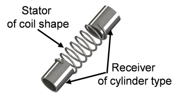
The external appearance of the active stent is indicated on Fig. 2. The active stent consists of two cylindrical receiving parts (receiver) where energy of ultrasonic vibration is received from vibration source and one coil shaped stator which outputs as drive force. SUS304 was used for the material of the active stent. When the actual use environment is assumed, about 3 mm is desirable for the outside diameter of the receiver. But, when dimension error in processing is considered, it's difficult to make a receiver of a designated resonant frequency. So, this time, the outside diameter which can think dimension error did not influence designed the cylindrical shaped receiver of 10 mm.
Fig. 1Stent of medical device
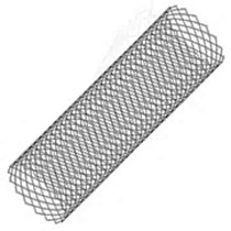
Fig. 2Schematic diagram of active stent
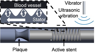
A concept about a drive mechanism of the active stent is indicated on Fig. 3. When the ultrasonic is irradiated from extracorporeal to the active stent in the body, the receiver of the active stent resonates, and a traveling wave occurs to the stator of the active stent. The active stent moves to the restenosis part by frictional force with inside wall of the blood vessel. By actual use method, the active stent is moved to left and right periodically because the restenosis does not occur, and a blood vessel is always maintained. And Langevin transducer was used as ultrasonic vibration source by this study.
Fig. 3Drive mechanism of active stent
3. Design of receiver
3.1. Analysis of receiver
Resonance phenomenon of the receiver is used for drive of the active stent. A receiver with the same resonant frequency as Langevin transducer of vibration source is made. The outside diameter of the receiver which assumed actual use is about 3 mm, but the production of the receiver with the resonant frequency designated by influence of dimension error is difficult. So, the receiver is designed as a triple model because influence of dimension error is not included in this study.
The previous study shows that the thickness of the receiver changes a resonant frequency of a receiver. To make the triple model, the receiver with the resonant frequency of the target is made from fixing the external shape of the receiver and controlling the inside diameter of the receiver. On the other hand, the resonant frequency of the receiver changes by the additional mass of the water in the water. So, receivers with the surrounding resonant frequency of the target resonant frequency are made in this research. The receivers are made based on the relation between the resonant frequency obtained from the eigenvalue analysis result and the inside diameter.
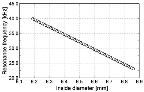
Creo Parametric 3.0 was used for an eigenvalue analysis and the modeling. The model used in the eigenvalue analysis is indicated on Fig. 4. The models which were changed the inside diameter of the receiver from 6.19 mm to 6.86 mm by 0.01 mm were made and the eigenvalue analyses were performed respectively. But, the resonant frequency in the air was acquired by the eigenvalue analysis because handling of the additional mass was difficult for the eigenvalue analysis which assumed in the water. When the eigenvalue analyses were carried out, attention was paid enough to get the same mode of vibration of the lower order. An analysis result of mode of vibration is indicated on Fig. 5. The results of the eigenvalue analysis to changes in the inside diameter of the receiver are indicated on Fig. 6. The resonant frequency is changing in linear way to changes in the inside diameter of the receiver.
Fig. 4Analysis model of receiver
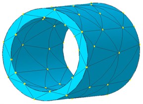
Fig. 5Vibration mode of receiver
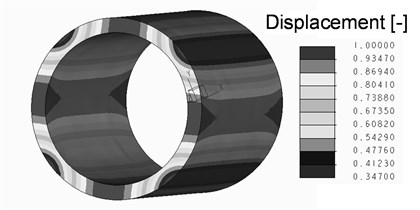
Fig. 6Result of eigenvalue analysis for receiver
3.2. Resonance experiment of receiver
The receivers with the same size as model of the eigenvalue analysis were made. The resonance experiments were carried out in the water using these receivers. The experimental equipment for the resonance experiment is indicated on Fig. 7. Ultrasonic vibration is irradiated to the receiver from horn tip of Langevin transducer including the receiver in the water tank. The amplitude of the impressed voltage is 40 Vp-p. Displacement on the receiver surface was measured by laser displacement meter and FFT analysis was performed to the displacement.
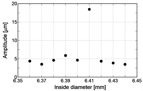
The result of the resonance experiment is indicated on Fig. 8. The amplitude of the receiver of inside diameter 6.41 mm is about three times compared with other receivers. Therefore, it is understood that the receiver of inside diameter 6.41 mm resonates. Based on the result, the receiver of inside diameter 6.41 mm is used for the active stent.
Fig. 7Experimental equipment for resonance experiment of receiver
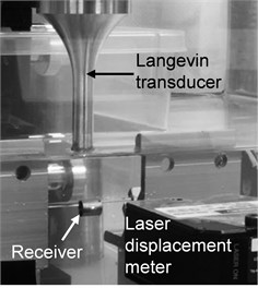
Fig. 8Result of resonance experiment for receiver
4. Resonance experiment of the active stent
4.1. The active stent based on analysis result
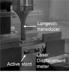
An experimental model of the active stent is indicated on Fig. 9. The wire diameter of the coil shaped stator is 0.7 mm, and the pitch is 1 mm, and the wire turns are 7 laps. And based on the preceding section, the receiver of the active stent is inside diameter 6.41 mm. The resonance experiment was carried out using the experimental model of the active stent in the water. The experimental equipment is indicated on Fig. 10. Ultrasonic vibration is irradiated to the receiver from horn tip of Langevin transducer including the active stent in the water tank. The amplitude of the impressed voltage is 30 Vp-p. Displacement on the receiver surface was measured using the laser displacement meter and FFT analysis was performed to the displacement. It was experimented on in the water, but the active stent did not resonate.
Fig. 9Experimental model of active stent
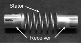
Fig. 10Experimental equipment for resonance experiment of active stent
4.2. Resonance search of the active stent
The models which were changed the inside diameter of the receiver of the active stent from 6.40 mm to 6.50 mm by 0.01 mm were made. The resonance experiment was carried out by the condition like the preceding section. The result of the resonance experiment is indicated on Fig. 11. The amplitude of the active stent using the receiver of inside diameter 6.44 mm is about twice compared with other active stents. Therefore, it is understood that the active stent of inside diameter 6.44 mm resonates.
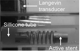
Next, the resonance experiment was carried out to the active stent in the silicon tube in the water tank. The experimental equipment is indicated on Fig. 12. The active stent was resonating, but movement in the silicon tube was not observed. It is considered as the cause to be lacking in the ultrasonic energy irradiated to the receiver because the electric power of the ultrasonic vibration source used by this study is about 30 W.
Fig. 11Result of resonance experiment for active stent
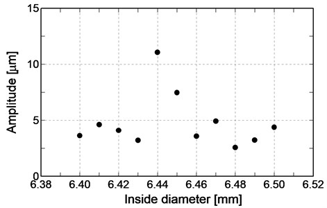
Fig. 12Experimental equipment for resonance experiment in silicon tube
5. Summary
A design and a resonance experiment of the active stent were performed for the purpose of drive of the active stent in the silicon tube in the water. For the purpose, the receiver was designed using the eigenvalue analysis, and the receiver which resonates in the water by the resonance experiment was specified. The experimental model of the active stent was made using the receiver which resonates in the water. However, when the resonance experiment was carried out using the experimental model of the active stent, the active stent did not resonate. So, the experimental models of the active stent which changed the inside diameter of the receiver of the active stent were made. When the resonance experiment was made using the experimental models of these the active stent, the active stent which resonates was specified. The resonance experiment was carried out in the condition that the active stent was installed in the silicon tube, but the active stent did not drive in the silicon tube. Because lack of the ultrasonic energy irradiated to the receiver is considered as the cause, it will be expected to experiment with the high voltage condition of the ultrasonic in the future.
References
-
Sashida T., Kenjo T. An Introduction to Ultrasonic Motors. Oxford University Press, Oxford, 1993.
-
Takesue N., Ohara T., Ishibashi R., Toyama S., Hoshina M., Hirai Y., Fukaya N., Arata J., Fujimoto H. Position control methods of spherical ultrasonic motor. Proceedings of IEEE/RSJ international conference on intelligent robots and systems, 2010, p. 3061-3066.
-
Moriya T., Furukawa Y., Akano Y., Nakajima A. Experimental Study on a Miniature Ultrasonic Motor Using a Coiled Stator. IECEI Technical Report, No. US2005-29, 2005, p. 41-45, (in Japanese).
-
Toyama S., Nishizawa U., Oohashi T. Intravascular stent motor powered by ultrasonic irradiation. Vibroengineering Procedia, Vol. 3, 2014, p. 346-350.
About this article

This work was supported by JSPS Kakenhi Grant Number JP15K 05756, JP16H04253, and Kawai Foundation for Sound Technology and Music.
