Abstract
The low-frequency and large-amplitude coupled vibration of the support sting in wind tunnel affects the accuracy of the wind tunnel test’s data. An active vibration control system of support sting in wind tunnel is demonstrated using adaptive control method in this paper. Following the establishment of the finite element model, and the extraction of parameter matrix, the original model is reduced to lower-mode model which contains first two pitching modes based on DC gain ranking method. The active control model is proposed based on model reference adaptive control method (RACM) to control the low-frequency vibration of supporting sting in wind tunnel. Research results have justified the effectiveness of the controlled system and provided insight into the practical application of the proposed method.
1. Introduction
Wind tunnel test is an indispensable part of the designed process of the aircraft, which has played an important role in analyzing the aerodynamic performance of the aircraft under complex flight conditions [1]. The support sting method is applied in the wind tunnel test of the large attack angle of the aircraft because of its simple structure and less interference effects [2]. The low-order natural frequency of the cantilever rod and the aerodynamic load in wind tunnel test are closed, which causes the low-frequency and large-amplitude coupled vibration [3].
In the initial study, the passive control method such as damper is used to decrease the vibration of the support sting, but the effect was limited [4]. R. W. Moses used a pure proportional control method to decrease the vertical vibration of the F-18 model by applying a piezoelectric actuator [5]. Khot. S. M. designed PID control method based on the output feedback controller, which had a reference value [6]. The flexible cantilever structure is one of the main structures in the active vibration control study. The research results have some references for the vibration control of the support sting [7]. Chen adopted the learning control strategy to control the system, and the effectiveness of the designed system was evaluated by a large number of ground tests [8]. Li used the hybrid fuzzy PID control method to control the vibration of the support sting and had the experimental study [9].
Model reduction is an effective way to improve the efficiency of analysis. The model reduction based on the DC gain ranking method orders the modes by the contribution size of each mode which relates to the overall response. In this paper, the high-order finite element model established by ANSYS is reduced by the model reduction method based on DC gain ranking and the low-order model is extracted. The model reference adaptive control method is proposed to control the low vibration of the support sting. The vibration suppression effect of the improved adaptive control method is verified by simulation with MATLAB.
2. Model reduction based on DC gain ranking method
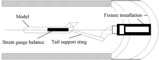
The typical support sting is illustrated as Fig. 1.
Fig. 1Wind tunnel model with support sting
Considering the degrees of freedom of the system, the finite element equation is:
where is the mass matrix, is the damping matrix, is the stiffness matrix, is the acceleration vector, is the velocity vector, is the displacement vector. is the drive position matrix. is the number of the drive. is the control force vector. is the external force position matrix. is the number of the external force. is the external force vector.
The physical coordinates are transformed into modal coordinates by using the following coordinate transformation:
where is the displacement response in modal coordinates.
Defining the state variables , Eq. (1) is expressed as:
where system matrix , ; input matrix , , is the line of the matrix . The selection of is related to the expected output value, is the direct transfer matrix, usually it is . is the th natural frequency of the system, is the th modal damping. is the -dimension input vector, is the output vector.
The transfer function by applying the excitation at the th degree of freedom in the th mode and getting the displacement response at the th degree of freedom is as follows [10]:
Adding all the modes contribution to the transfer function, the system transfer function is as follows:
In this paper, the ‘DC gain’ is used as the index to measure the contribution of different modes to the whole response. For the th mode, the transfer function is defined as the DC gain when is set. The DC gain which is determined by the corresponding eigenvector and eigenvalue is as follows:
The magnitude of the DC gain characterizes the importance of the different modes in the whole structural response. For the wind tunnel support sting, the DC gain of each mode which is calculated before is ordered, then the mode that does not contribute to the whole response is removed, and the mode that affects the structural response in the pitch direction is leaved, then the reduced model whose dynamic characteristics of the structures is not affected is obtained.
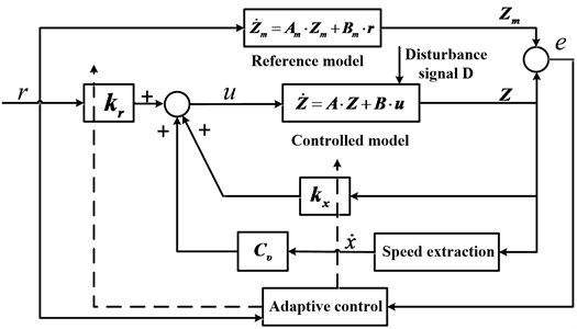
3. Model reference adaptive controller designs
Controlled system is the reduced model like Eq. (3). Considering introducing the following reference model (same dimensions as the controlled system):
where is the state variables of the reference model, is the -dimensional reference input vector, , are the constant matrices.
Considering coupling velocity feedback based on original controller to get the new controller, the structure of model reference adaptive control algorithm is as follows:
where is the velocity feedback matrix., are the adaptive control gain matrices to be designed, they are solved as follows:
where and are the diagonal positive constant matrices. is the symmetric positive constant matrix, for any given symmetric positive constant matrix , there is the symmetric positive constant matrix that satisfies following Lyapunov equation:
Combining the Eq. (3) and Eqs. (7-8) to get the state equation about the state error signal:
The principle of designed control method for the wind tunnel support sting is as Fig. 2.
Fig. 2The diagram of model-reference adaptive control system
4. Simulation of control system
In this paper, the support sting is simplified into a cantilever rod which is added lumped mass in the free endpoints. The added mass element is 3DMASS21. The model is illustrated as Fig. 3. A modal analysis is taken to get the first fifth order modes, the analysis results are illustrated as Table 1. The system matrices of controlled structure from ANSYS are extracted by using MATLAB program, and then, the mathematical model of the controlled structure is established.
Fig. 3FEM model of wind tunnel model with support sting
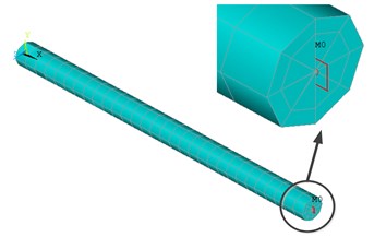
Table 1The first five frequencies of controlled structure
Order | 1 | 2 | 3 | 4 | 5 |
Frequency / Hz | 5.004 | 5.006 | 19.304 | 19.307 | 356.19 |
The first 20 order modes of the model are taken by ANSYS to characterize the whole model. The model reduction method is used to reduce model containing only the first two modes (the excitation point and the response point are in the number 146 degrees of freedom).
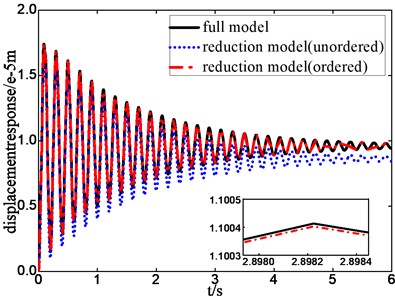
the frequency response curves and the step response curves of the full model ,the unordered reduction model and the ordered reduction model are illustrated in Fig. 4-5. It is seen that ordered reduction model reserves the low-order modes what we care about and can accurately describe the dynamic characteristics of the structure in the pitch direction. So, it is reasonable to use the ordered reduction model as analysis model.
Fig. 4Frequency response of full model and reduction model
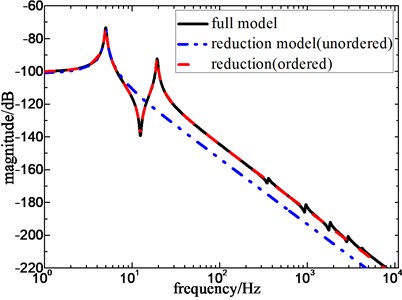
Fig. 5Step response of full model and reduction model
In this paper, the reduction coefficient method [11] is introduced to select the reference model, choosing reduction coefficient , adaptive control coefficient , velocity feedback gain matrix . The frequency response with or without control are illustrated as Fig. 6. The step response with or without control are illustrated as Fig. 7. It is seen that the amplitude at the resonant frequency is effectively decreased, the designed controller has better control effects on the first two order pitch modals of the structure.
Fig. 6Frequency response with and without control
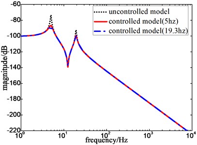
Fig. 7Step response with and without control
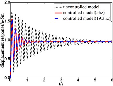
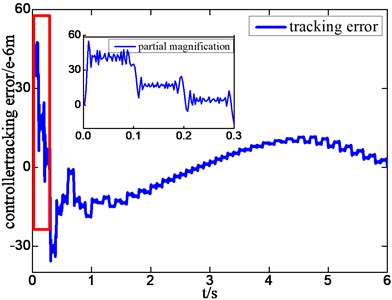
The tracking error curves of controlled model and reference model are illustrated as Fig. 8. It is seen that the designed controller has an adaptive period under the excitation, gradually, the general error approaches zero. The displacement response curves of structures with and without control are illustrated as Fig. 9. It can be seen that the amplitude is decreased to 12 % compared to the original response, the response of structure meets the required dynamic characteristic.
Fig. 8Position tracking error of adaptive controller with excitation
a) Frequency of external force is 5 Hz
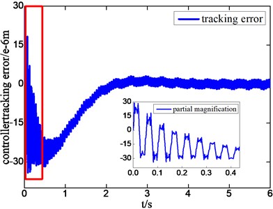
b) Frequency of external force is 19.3 Hz
Fig. 9Displacement response with excitation of different frequency
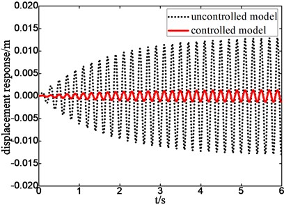
a) Frequency of external force is 5 Hz
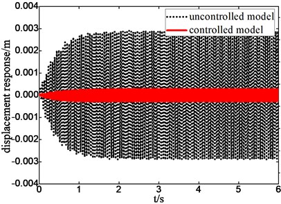
b) Frequency of external force is 19.3 Hz
5. Conclusions
In this paper, active vibration control of the support sting in wind tunnel is studied. The finite element model is established by ANSYS, the parameter matrix is extracted by MATLAB, and the low-mode model is obtained based on DC gain ranking method. The dynamic characteristic of the reduced structure is characterized by frequency response and unit step response of the full model and ordered-reduced model. The model reference adaptive control (MRAC) method is used to control structure response. The adaptive process, the stability and the controlled effectiveness are compared both at time domain and frequency domain. It can be seen that the model reference adaptive control method is valid for the problem of support sting vibration control.
References
-
Christensen P., Robertson P. Methods for increasing wind tunnel testing effectiveness. US Air Force T&E Days, Los Angeles, 2008.
-
Ocokoljic G., Rasuo B., Kozic M. Supporting system interference on aerodynamic characteristics of an aircraft model in a low-speed wind tunnel. Aerospace Science and Technology, Vol. 64, 2017, p. 133-146.
-
Taylor G., Gursul I., Greenwell D. An investigation of support interference in high angle of attack testing. Aerospace Sciences Meeting and Exhibit, Nevada, 2003.
-
Capone F. J., Igoe W. B. Reduction of Wind-Tunnel-Model Vibration by Means of a Tuned Damped Vibration Absorber Installed in the Model. NASA-TMX-1606, Washington, 1968.
-
Wimmel R. Active electronic equipment DOF suspension for high loads as vibration, shock and quasi static forces. Proceeding of The European Conference on Spacecraft Structures, Materials and Mechanical Testing, The Netherlands, 2005.
-
Khot S. M., Yelve N. P., Tomar R., et al. Active vibration control of cantilever beam by using PID based output feedback controller. Journal of Vibration and Control, Vol. 18, Issue 3, 2012, p. 366-372.
-
Wedegiorgis R., Krishna P., Gangadharan K. V. Vibration control of smart cantilever beam using strain rate feedback. Procedia Materials Science, Vol. 5, Issue 5, 2014, p. 113-122.
-
Chen W. D., Shao M. Q., Yang et al. X. H. Experimental evaluation of an active vibration control system for wind tunnel aerodynamic models. Journal of Vibration Engineering, Vol. 1, 2007, p. 91-96, (in Chinese).
-
Li G., Dong C., Wang Q. Active vibration control for wind tunnel model using hybrid fuzzy-PID scheme. International Conference on Fuzzy Systems and Knowledge Discovery, 2009.
-
Hatch M. R. Vibration Simulation Using MATLAB and ANSYS. Chapman and Hall/CRC, Boca Raton, Florida, 2001.
-
Qu W. L., Zha X. P. Application of minimal control synthesis algorithm to structure vibration control. Journal of Wuhan University of Technology, Vol. 29, Issue 1, 2012, p. 145-148, (in Chinese).
About this article

