Abstract
Planetary gears in wind power plants transmit force excitations to the mechanical structure due to alternating tooth meshes. Structure-borne sound is generated and proceeds to tower and nacelle where it is radiated to the environment and may be a noise pollution to residents. In addition, unwanted vibrations can decrease the durability of the gearbox. So far, structural vibrations are being avoided by constructive measures or active absorbers. In contrast to this, our approach is to reduce gear mesh excitations only with the existing electric generator. Therefore, the rotor current control of the machine is enhanced to inject high frequency oscillations so that the wind power generator produces a specific oscillating torque. This anti-noise torque ripple is transmitted via the shaft to the gear stage and minimizes the gear mesh orders so that less force excitations are exposed to the mechanical structure at the bearings. In our knowledge this anti-noise torque approach using the electric generator and its current control is completely new in the field of wind power plants. Simulation is performed using a multi-body-model of the drivetrain to identify an optimal torque oscillation. Afterwards a control circuit model of the generator and the power converter for the rotor circuit is shown. Hence, it is possible to calculate the behavior of the system in high level of detail on the mechanical and the electrical side. Resulting bearing forces are analyzed to prove that excitation can be reduced significantly. No additional hardware, especially no additional actor is needed.
1. Introduction
Doubly-fed induction generators (DFIG) in wind power plants are coupled to the rotor blades via a planetary gearbox. The stator of the generator is directly connected to the grid while the rotor windings are fed by slip-rings and a converter, see Fig. 1. In this way, the rotor currents are controlled to achieve a variable speed drive which is important to capture maximum wind energy [1]. The biggest advantage of this wind turbine type over direct drives with a full converter is that the power electronic components only process the rotor power which is typically less than 25 % of the overall output and this results in lower costs and power losses. However, a planetary gearbox is necessary which has to meet specific requirements concerning durability and noise production.
The acceptance of wind turbines within the population depends very much on low noise emissions. One perception often stated by residents is that the turbines emit low-frequency, amplitude-modulated noise leading to stress symptoms [2]. Noise produced by the drive system, consisting of converter, current control, electric machine and gearbox, must be analyzed in the context of the overall system structure [3]. The dominant sources of structure-borne noise are caused by the magnetic circuit geometry of the machine [4], the supply with current harmonics due to pulse-width-modulation (PWM) [3] and the mechanical gear mesh excitation in the gearbox [5]. All three effects lead to structural vibrations and can be influenced by the drive control.
Fig. 1Doubly-fed induction generator wind turbine system overview
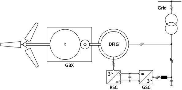
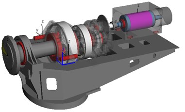
Fig. 2SIMPACK wind power plant MBS model
Structural vibrations in wind turbines are a disturbing noise source and reduce the durability of the drive train. Tooth mesh frequencies within the planetary gearbox lie within the range of 100 up to 600 Hz [6]. They are transmitted as structure-borne sound from the gear wheels to the bearings. Afterwards, vibrations are transmitted through the impact noise insulation to the nacelle bedplate and finally to the tower where they are emitted as airborne sound. Due to their narrow-band characteristic, they are noticeable as single tones in the noise spectrum. One possible solution is damping of the structural vibrations using active absorbers coupled to the machine carrier structure at the nacelle bedplate [6]. These additional actors need extra energy and add costs, the dynamic structural coupling and positioning of the actor is a complex task and they do not reduce the excitation and can therefore not ensure the durability of the gearbox.
For these reasons, we are investigating active noise reduction methods by enhanced control algorithms of the generator itself without any additional absorbers. The principal method has been developed in small scale at spur gears and brushless-dc machines using FxLMS control methods [7]. However, it must be adapted to be implemented using the rotor current control at a DFIG wind-power plant.
2. Multi-body-simulation of wind turbine gearbox
2.1. Modeling the drivetrain
A torsional reduction of gear mesh orders shall be demonstrated by a wind turbine gearbox multi-body simulation (MBS) model within a 5 MW wind turbine. The complete model can be seen in Fig. 2. In addition to the main components – rotor, rotor shaft, machine frame and DFIG – the gear unit is modeled in detail. It consists of three gear stages: the first two stages as planetary gear units with fixed ring gears and the third stage as a helical spur gear stage, see Fig. 3.
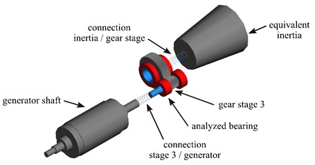
The aim of this study is to consider the structure-borne gear mesh noise excitation of the spur gear stage at the generator side as an example. Firstly, the model is reduced due to the large number of degrees of freedom (DoF) of the overall system shown in Fig 3. For model reduction, the inertias of rotor, rotor shaft and the two planetary stages are converted to one overall equivalent inertia by means of image shaft transformation [8]. This results in a system with one helical spur gear stage with input and output shaft containing inertia properties of adjacent components. The model reduced to the last gear stage is illustrated in Fig. 4, where the gear shafts as well as the rolling bearings, gears, equivalent inertia and the DFIG rotor are shown.
It should be noted that, in order to further reduce the model DoF, no elastic structures, such as the machine carrier or the gearbox housing, have been taken into account. Thus, the illustrated model is a simplified representation of the overall system. In the reduced model, all gearbox components were considered as rigid bodies with six DoF since radial and axial bearing forces are used for evaluation. The reduced model has 14 DoF resulting from two 6-DoF gearbox shafts, a 1-DoF generator shaft and a 1-DoF rotor shaft where only the torsional DoF is considered. In contrast, the full model has more than 100 DoF due to the large number of 6-DoF-bodies and due to the number of elastic modes used for representation of the dynamic properties.
Within the presented numerical investigations, a steady-state operation condition with constant input and output torques as well as a constant speed is considered for the reduced model. The goal is to demonstrate the application of a control algorithm to reduce gear mesh excitations. Using a more detailed model requires the identification of critical operating conditions from an acoustical point of view which differs from this reduced model. Hence, the usage of more detailed models will lead to different operating conditions but the effect of reducing gear mesh excitations will remain the same – just for differing frequencies and magnitudes.
All mass properties of the reduced drivetrain model have been determined based on geometry for the gearbox shafts and, in terms of rotor and generator, based on mass properties of adjacent components. In order to consider gear mesh excitations, the gears were modelled in detail based on tooth macro geometry parameters. The external loads have been applied as constant torques at generator and rotor shaft which are coupled to gearbox shafts utilizing torsional spring/damper elements representing the clutches of the original system. The support of the two 6-DoF gearbox shafts has been realized by four spring/damper elements representing the bearings of the gearbox in floating/fixed configuration.
Fig. 3Full DoF detailed gearbox model
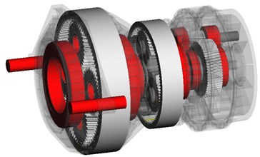
Fig. 4Reduced DoF model
2.2. Identifying an acoustically optimized generator torque output
The reduced model is used to identify an optimized generator output torque that minimizes vibration exciting bearing forces in specific tooth mesh orders. At first we evaluated the initial condition without vibration compensation for a selected load case (constant torque of the generator 30 kNm at constant speed 550 rpm). Fig. 5 shows the spectra of radial and axial forces at the rotor-side roller bearing of the high-speed output shaft for a constant generator torque.
Note that in both force component spectra the first order of tooth meshing at 175 Hz can be identified as the dominant order with an amplitude of 12 kN in radial direction. The radial bearing force amplitude is much higher than the axial one. This is an ideal result due to simplification because in the reduced model only the helical spur gear excitation is present.
Based on the results shown, the compensation of this first order is described in more detail as follows. We are superimposing the constant generator torque with an additional sinusoidal component. The frequency of the torque oscillation corresponds exactly to the first harmonic of the gear mesh frequency . Generator torque output then is a function of time:
Fig. 5Force spectra of radial and axial bearing forces with tooth meshing orders at constant generator torque (1st order at 175 Hz)
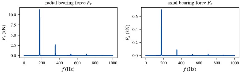
Fig. 6Amplitudes of radial and axial bearing force in first order of tooth meshing depending on amplitude and phase of the superimposed sinusoidal generator torque output
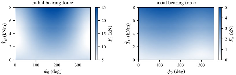
Both, amplitude and phase , need to be identified in order to reduce the exciting bearing forces. Therefore we performed a parameter study with the reduced model under consideration of the first harmonic amplitude of the gear mesh order, see Fig. 6. It can be seen that the force amplitudes have distinct minima within the chosen parameter limits. Because of the fact that the radial amplitude is much higher, a generator torque amplitude of 3.17 kNm and a phase of 0 deg is desirable to minimize tooth force excitations of structure-borne sound of the first gear stage. The amplitude of the radial bearing force amplitude can be lowered from 12 kN (see Fig. 5) to 5 kN which is a reduction of approx. 60 %.
In Fig. 6 it can also be seen that there is a strong dependency of the resulting forces on the phase angle. This is feasible because the superimposed torque oscillation potentially increases or decreases the vibrations depending on the relative phase between the torque and the tooth mesh. However, the minima of axial and radial bearing force cannot be found at the same amplitude and phase. Yet the reduction of the radial component is much higher which leads to an overall improvement.
In order to provide a holistic system analysis, the exact transfer path between the excitation force at the bearings and the vibration of the housing can be considered in detail. The generator itself has to hold up the oscillation torque via its stator and its coupling to the machine frame. Four elastomer supported bed-plates decouple the structure-borne sound of the generator from the machine frame. Due to the oscillation torque, higher vibration excitations are expected at the stator side of the generator. However, they are damped by the elastomer bed-plates which is why a reduction of the vibrations can be expected using the described method.
The aim of this study is to show the possibilities of directly influencing the generator control to reduce vibrations due to gear mesh excitations. Fig. 6 clarifies that tooth mesh excitation force amplitudes can be lowered significantly providing an optimal generator torque.
2.3. High dynamic rotor current controller
From a control system perspective, the question is whether the generator will be able to provide the desired high dynamic torque oscillation (i.e. at 175 Hz) needed for noise reduction of the gearbox.
The overall system design was already mentioned in the introduction, see Fig. 1 for reference. The rotor side converter (RSC) implements a machine variable speed control using a rotor current controller that must be enabled to provide a high dynamic current oscillation. Therefore, we investigated the dead-beat control behavior of the rotor currents instead of PI control to ensure maximum dynamic [9].
2.4. Control model including the PWM control of the inverter
To determine the achievable torque dynamics, a simulation was set up containing the following submodels:
1) Stator supply grid, orientation to the grid voltage by means of a PLL.
2) Continuous-time machine model in state-space representation (cf. [9]) with constant parameters without nonlinear effects at constant speed operating point.
3) Inverter model with idealized switching behavior and space vector modulation with fixed pulse frequency of 4 kHz; constant DC link voltage without grid-side control.
4) Dead-beat controller [9] with fixed sampling rate also at 4 kHz.
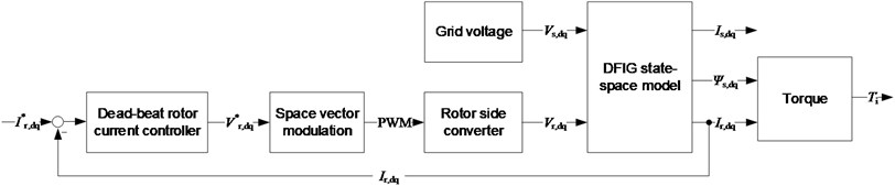
Fig. 7 shows the components of the control model including all interfaces. The aim of the model is to determine the dynamics of the current control, taking into account the inverter switching behavior and the fixed clock rate, and to prove that the oscillation torque determined in the previous section can be provided by the generator including its PWM rotor current control.
Fig. 7Control model overview for simulating the achievable torque dynamics
3. Simulation results
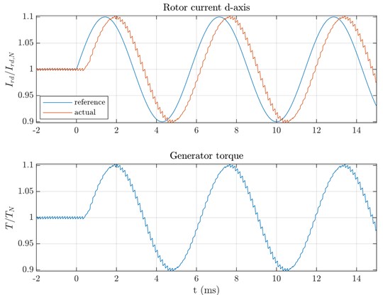
The control model is used to simulate the generation of an oscillating torque with realistic control dynamics. After the transient process has been completed and constant operation at nominal point of the generator is achieved, an oscillating torque is desired to accomplish noise reduction. At this operating point, the frequency of the required oscillation torque is 175 Hz and the amplitude is 3.17 kNm at 30 kNm constant torque component. As a simple approach this oscillation is given to the set point of .
Fig. 8 shows the simulation result. The influence of the discrete sampling with a fixed pulse frequency of 4 kHz can be clearly seen. The adjustment of the desired oscillating torque to influence the first gear mesh order of the gearbox is possible without any problems. A phase shift between reference and actual current is caused by the controller and has to be compensated in the application of the method.
Depending on the selected operating point of the generator, the frequency of the first gear mesh order can shift upwards. However, it can be concluded that an oscillating torque in the relevant frequency range can be provided by the generator without any problems.
Fig. 8Simulation results for oscillating torque output via rotor current dead-beat control
4. Conclusions
We investigated vibration reduction methods by influencing gear mesh orders in a DFIG wind power system with a planetary gearbox. Therefore, we performed MBS simulation to find an optimal torque oscillation that is capable of reducing bearing force excitations. These forces excite the machine frame due to the tooth mesh of the first gear stage. Parameter study on the amplitude and phase of an oscillation torque has shown that it is possible to reduce the radial excitation forces as main force component at the investigated bearing by 60 %. In addition, we developed a control system simulation to prove that it is possible to provide that torque oscillation by the generator. Therefore, we created a time-discrete dead-beat controller for the rotor currents that has a much better dynamic behavior than conventional PI controllers taking into account the discrete step PWM control of the rotor-side power electronic converter. In this example, the first gear mesh frequency of 175 Hz with an amplitude of approx. 10 % of the constant torque could be provided without any problems. To our knowledge this high-dynamic generator control to produce an anti-noise torque is completely new in the application at wind power plants. However further investigations have to be executed to prove this simulation result on a laboratory-scale test-bench.
References
-
S. Muller, M. Deicke, and R. W. de Doncker, “Doubly fed induction generator systems for wind turbines,” IEEE Industry Applications Magazine, Vol. 8, No. 3, pp. 26–33, 2002, https://doi.org/10.1109/2943.999610
-
J. Pohl, J. Gabriel, and G. Hübner, “Understanding stress effects of wind turbine noise – the integrated approach,” Energy Policy, Vol. 112, pp. 119–128, Jan. 2018, https://doi.org/10.1016/j.enpol.2017.10.007
-
Thomas Windisch, Jan Bräunig, Jan Troge, and Welf-Guntram Drossel, “Advanced control algorithms to suppress high-frequency PWM current and force harmonics in highly integrated electric vehicle drives,” in 11. Aachen Acoustics Colloquium 2019, November 25-27, 2019, Pullman Aachen Quellenhof, Germany, Nov. 2019.
-
J. F. Gieras, C. Wang, and J. C. Lai, Noise of Polyphase Electric Motors. CRC Press, 2018, https://doi.org/10.1201/9781420027730
-
H. Linke, Stirnradverzahnung: Berechnung – Werkstoffe – Fertigung. München Wien: Carl Hanser Verlag, 2010.
-
A. Illgen, W.-G. Drossel, V. Wittstock, F. Mitsch, K.-H. Hanus, and L. Wiedemann, “Passive and active dynamic vibration absorbers for gear box noise reduction in wind turbines,” in International Conference on Wind Turbine Noise, 2007.
-
Timo Benzel and A. Moeckel, “Active gear pair vibration control during non-static load and speed with an electronically commutated motor as actuator,” in ETG/GMM-Symposium Innovative small Drives and Micro-Motor Systems, 2015.
-
H. Dresig and F. Holzweißig, Dynamics of Machinery, Theory and Applications. Springer, 2010.
-
N. P. Quang and J. A. Dittrich, Vector control of three-phase AC machines / System Development in the Practice. Springer, 2008.
About this article

