Abstract
The article describes a method for active reduction of magnetic noise generated by a magnetic field that exists in the airgap of an induction motor. In this article a mathematical model of the process of magnetic noise excitation in a stators is presented. The model take into account that magnetic field waves, radial magnetic force waves (so-called Maxwell forces) and stator deformation waves (magnetic noise) are characterized by their own values of amplitude, mode number, frequency and phase shift. By comparing the equations for calculating the stator mechanical impedance, the amplitude of the radial magnetic force and the simplified magnetic noise equation, the relationships between these variables were established. The method of active reduction of magnetic noise proposed in the article is based on the use of these relationships. The novelty of the proposed method lies in the use of the filtered spectrum of output signal of the accelerometer installed on the stator to determine the most intense harmonics of the magnetic field in the motor airgap in order to further suppress them. The compensation signal generated by a special device adapts not only in frequency, but also in phase and amplitude of each vibration-disturbing harmonic.
Highlights
- The proposed magnetic noise reduction method is based on the use of the filtered spectrum of output signal of the accelerometer installed on the SCIM stator.
- The compensation signal generated by active compensating device adapts in frequency, phase shift and amplitude of each vibration harmonic. This signal and reference signal are fed to the PWM controller.
- The device allows to compensate the time delay caused by the mechanical impedance of the SCIM stator and the computation time of FFT unit.
- It is found that the proposed method makes it possible to reduce the radial magnetic force by 20% and magnetic force harmonics by 50-70%.
1. Introduction
Magnetic noise associated with the magnetostriction of the stator steel is a problem for almost all medium/high power motors [1-6]. It leads to many unfavorable phenomena: a change in the harmonic composition of the supply voltage, wear of bearings, acoustic noise, an increase in power consumption and destruction of electric motors [3-6].
Magnetic noise is especially pronounced in asynchronous Squirrel-Cage Induction Motors (SCIM) characterized by a rotating magnetic field relative to the stationary stator. The radial magnetic force (Maxwell force) in such machines causes periodic deformation of the stators, which manifests itself primarily as acoustic noise. However, the amplitude of the stator deformation can exceed 0.3 mm [4].
A lot of works are devoted to the study of magnetic noise excitation and development of methods and means to reducing it. In the 70-80s. I.G. Shubov, N.V. Astakhov, V.S. Malyshev, N. Y. Ovcharenko et al. laid an extensive fundamental base for the mathematical description of magnetic noise excitation in electric motors and structural methods for their reduction [2, 5]. In the 90-00 years in the works of D. Belkhayat, B. Cassoret, R. Corton, K.C. Maliti, D. Roger and other scientists disclosed ways to active reduction of the magnetic noise in SCIM by affecting the harmonic composition of the supply current by injection a special compensating signal [4, 7-9]. Thus, the Belkhayat method is based on calculating the radial magnetic force by the stator current. This method operates allow to reduce a certain harmonic of the radial force by 10 times [7]. The Cassoret method based on calculating the magnetic induction from the values of the electromotive forces (e.m.f.) and magnetomotive forces (m.m.f.) of the stator and rotor windings [8]. This method provides reducing of force waves by 2-3 times in a wide frequency range.
Fundamentally new approaches are proposed by the methods described in the works of the last decade, prepared by D. Franck, K. Hameyer, V.V. Davydov, N.A. Dobroskok and other scientists [3, 10, 11]. This methods are based on the change of angles and amplitudes of voltages in the vector control system of an SCIM-based electric drive. In the Franck's method magnetic noise calculated by the functions of the m.m.f. and airgap permeance. This method allows to reduce the magnetic force by 2 times [10]. Dobroskok's method is based on the control of the phase shift angles of voltages of the vector diagram of the SCIM and allows to reduce the magnetic noise in a wide range by 3-4 dB [3]. The efficiency of the method has been confirmed experimentally, but its efficiency is relatively low.
The purpose of this article is to develop a new method for active reduction of magnetic in SCIM stators by changing the spectral composition of the supply current using compensating device with Fast Fourier Transform unit with the possibility of implementing it on microcircuit with digital signal processing.
Magnetic Noise Excitation in a SCIM
Pulsating and rotating Maxwell forces occurring in the airgap of defect-free SCIM are the main source of their vibration [5, 12]. The most intense are the radial magnetic forces that cause stator vibrations. This forces are proportional to the square of the magnetic field value in the SCIM airgap [1, 4, 5, 13]:
where is vacuum permeability, is time, is angular coordinate of airgap (rad.).
One of the ways to magnetic noise reduction in the SCIM suggests to control the magnetic field spectrum in the airgap [4, 13]. The most common is the method of active reduction of magnetic noise based on stator current control, in which an additional compensation harmonic (or several harmonics) are added to the fundamental current generated by PWM inverter. The essence of this method is described in detail in [7-9].
The radial magnetic force generated by the magnetic field in the airgap of SCIM powered by the PWM-inverter taking into account the compensation harmonic is equal to [3]:
where is magnetic field harmonic number, is 1st magnetic field harmonic, is -th magnetic field harmonic caused by injected current, is higher-order harmonic of the magnetic field due to stator and rotor slots, airgap unevenness, etc.
Since the injected current has small amplitude values (no more than 15 % of the supply current amplitude [3, 7-9]) we assume that the amplitudes of the radial magnetic forces determined by the values of the magnetic field in the airgap with the value and are negligible (index means peak value). Only two harmonics of the radial magnetic force generated by the interaction of the 1st magnetic field harmonic and the compensatory harmonic have a significant effect. These harmonics are described by equation:
where is 1st magnetic field harmonic amplitude, is -th magnetic field harmonic amplitude, is compensating harmonic amplitude, is pair of poles number, is magnetic field frequency, is phase shift of 1st magnetic field harmonic, is magnetic field frequency of injected harmonic, is phase shift of injected harmonic.
These harmonics of radial magnetic force have a mode number 2∙ and 0 respectively.
It is necessary to determine the most pronounced harmonic of the magnetic force. To do this it’s need to know its main parameters: frequency, amplitude and phase shift:
where is radial magnetic force amplitude, is mode number, is frequency of magnetic force (), is phase shift of magnetic force.
The harmonic with the mode number 0 according to [3, 5] remain and will cause vibrations, however, its amplitude will be much smaller compared to the force Eq. (4).
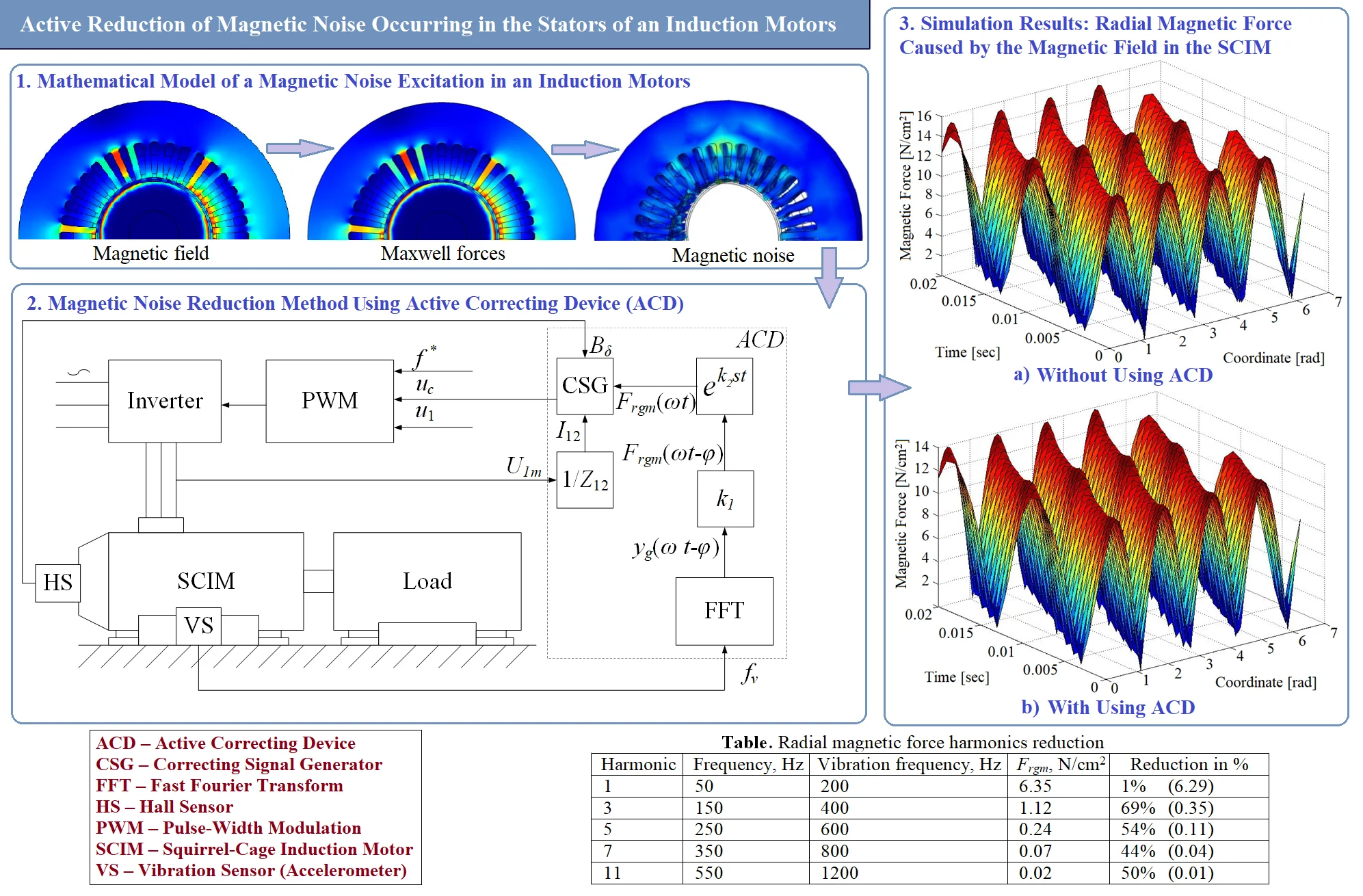
The mode number 0 implies uniform radial deformation of the stator along the entire airgap. Radial magnetic forces of the second mode number ( 2) and higher cause bending deformations of the stator as shown in Fig. 1 [5].
Fig. 1Mode numbers and shape of deformation of the stator yoke
Radial magnetic forces of one harmonic composition cause the magnetic noise of another harmonic composition [1, 4-6]. This is due to the fact that the stator of the SCIM characterized by its own frequency response with one or several natural frequencies. Therefore, harmonic composition of magnetic forces can be significantly different from the harmonic composition of vibrations. With mode number of 2 or more, the stator undergoes deformations of the -gon shape with a frequency equal to [5]:
where is the elastic modulus of the stator yoke, is the height of the stator back, is the stator radius, is the reduced mass of the stator yoke determined by:
where is the mass of the stator core, is the length of the stator.
Analysis of Eq. (5) allows us to conclude that vibrations with the mode number of 2 are characterized by the highest intensity, since their frequency is lower than that of other ones [3, 5]. At the same time, in the case of SCIM power supply from the PWM-inverter vibrations with mode number of 2∙ 4 also have a significant effect on the stator magnetic noise.
The mechanical impedance of the SCIM stator at the frequency determined as follows:
where is mechanical flexibility.
Since most intense vibrations arise due to the interaction of the first and higher harmonics of the magnetic field in the airgap of SCIM, radial magnetic force can be expressed as follows:
The amplitude values of magnetic force harmonics can be determined from the expression:
where is magnetic field in the airgap, is the inner radius of the stator, and are the amplitude and the phase shift of the -th harmonic of magnetizing current, and are the amplitude and the phase shift of the 1st harmonic of magnetizing current.
Using the obtained values it is possible to determine the values of the velocity amplitudes of the stator vibrations caused by the radial magnetic force [5]:
2. The essence of the method of magnetic noise reduction in a stator of SCIM
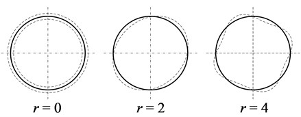
The radial magnetic force can be reduced by adding a special compensation current to the supply current to the stator windings of SCIM. In the method proposed by the authors, the compensation signal generates an active correcting device (ACD) by means of program analysis.
In [14], a method was considered for the generation of a compensation signal that reduces the torque pulsations of the SCIM using the Fast Fourier Transform (FFT) in real-time mode. Vibration signal registration is carried out using a vibration sensor (VS) attached to the motor. The VS output signal use for generating a compensation signal. The FFT unit converts and analyzes the vibration acceleration signal received from the VS and then the results of the spectral analysis are fed to the input of the ACD. The higher harmonics of the VS signal filtered in the FFT unit that includes a low-pass filter. This approach is also used in the proposed method.
The modes of magnetic force waves do not coincide with the modes of magnetic noise of the SCIM stator, which requires from the ACD system availability of information about the mechanical parameters of the SCIM and the electromagnetic processes occurring in it. The frequency of the fundamental harmonic of vibrations is equal to the doubled frequency of most intense harmonic of magnetic field of the SCIM. In the ACD system high-frequency interference is filtered out of the proportional vibration acceleration signal and harmonics with frequencies close to doubled power supply frequency are eliminated. Fig. 2 shows a diagram of an ACD system with a VS and a FFT for magnetic noise reduction of SCIM fed by PWM-inverter.
The vibration reduction of the SCIM is provided by means of PWM control. In the FFT unit a polyharmonic signal is formed which is a combination of the fundamental harmonic and higher harmonics taking into account phase delays. This signal is fed to a digital filter that includes a amplifier and phase delay compensator . The values of the coefficients and are calculated for each essential vibration harmonic.
The phase delay taken into account by the ACD system is the sum of the delay associated with the inertia of the stator structure and the computation time of the FFT unit can be offsetted in the phase delay compensator block. The value of the mechanical phase delay component depends on the mechanical parameters of the SCIM stator:
where is damping coefficient of the stator core, is stiffness coefficient of the stator yoke, is the stator deformation caused by magnetic force at the frequency :
where denote at number of FFT samples.
Fig. 2ACD system equipped with VS and FFT unit
The amplitude of compensation signal can be expressed through the vibration velocity as follows:
Finally, the Compensation Signal Generator unit (CSG) generates a signal , which together with the given signal is fed to the PWM controller. For the method to work effectively the PWM sampling rate must be at least 5 kHz. The current amplitude is determined as follows:
The amplitude of the magnetic field in the airgap can be measured with a Hall Sensor (HS), while the current can be determined according to the T-shaped transformer equivalent circuit from the known resistance values and value of the supply voltage [12]:
where , , are complex resistances of T-shaped transformer equivalent circuit.
3. Simulation results
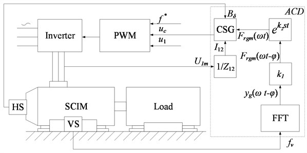
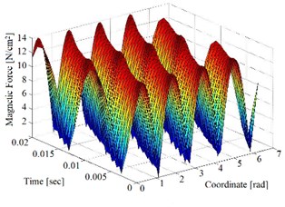
To test the operability of the method for active reducing the magnetic noise of the SCIM in the Matlab software a simulation model was developed. Radial magnetic force is calculated taking into account the compensation field. The simulation results are shown in Fig. 3 and represent 3D-graphs of the radial magnetic force in the airgap of the SCIM.
The results of the frequency analysis of the graphs shown on Fig. 3 made it possible to determine the amplitude values and the minimization of radial magnetic forces harmonics in percent’s, which are shown in Table 1.
Fig. 3Graphs of the radial magnetic force caused by the magnetic field in the SCIM
a) Without using the ACD
b) With using ACD
Table 1Radial magnetic force harmonics reduction
Harmonic No. | Frequency, Hz | Vibration frequency, Hz | , N/cm2 | Reduction in % |
1 | 50 | 200 | 6.35 | 1 % (6.29) |
3 | 150 | 400 | 1.12 | 69 % (0.35) |
5 | 250 | 600 | 0.24 | 54 % (0.11) |
7 | 350 | 800 | 0.07 | 44 % (0.04) |
11 | 550 | 1200 | 0.02 | 50 % (0.01) |
4. Conclusions
A new method has been developed for active reducing of magnetic noise occurring in SCIM stators. Approach for constructing an Active Correcting Device (ACD) that allows generating an additional compensation current of an electric motor by means of a PWM-inverter to reduce harmonics of the magnetic field is developed.
The simulation results showed that the proposed method makes it possible to reduce the radial magnetic force by 20 % (from 15.9 to 13.1 N/cm2) and magnetic force harmonics by 70 % (from 1.12 to 0.35 N/cm2) while the amplitude of vibration displacements decreased by 30 % (from 27.8 to 19.7 μm). Thus, modeling has confirmed that the proposed method for magnetic noise reducing is highly efficient and can be practically implemented.
In the near future it is planned to expand the described model to study the algorithms and parameters of the PWM-controller in terms of their influence on the quality of active reduction of magnetic noise, on the harmonic composition of the supply network and voltage on the stator winding of the motor. In addition, the mechanical model of the motor will be compiled based on the study results of the finite element model of the SCIM stator.
References
-
Cheraghi M., Karimi M., Booin M. B. An investigation on acoustic noise emitted by induction motors due to magnetic sources. Power Electronics Drives Systems and Technologies Conference (PEDSTC), 2018, p. 104-109.
-
Astakhov N. V., Malyshev V. S., Ovcharenko N. Y. Mathematical Modeling of Vibrations of Asynchronous Machines. Shtiintsa, Chisinau, 1987, p. 145, (in Russian).
-
Dobroskok N. S. Algorithmic Methods of Noise and Vibration Reduction in a Frequency-Controlled Induction Electric Drive. Ph.D. dissertation, Saint-Peterburg, 2014, p. 162, (in Russian).
-
Maliti K. C. Modeling and Analysis of Magnetic Noise in Squirrel-Cage Induction Motors. Ph.D. Thesis, Stockholm, 2000, p. 209.
-
Shubov I. G. Noise and Vibration of Electrical Machines. Energoatomizdat, Leningrad, 1986, p. 208, (in Russian).
-
Leleu E., Espanet C., Miraoui A., Siala S. Analytical modelling of electromagnetic origin vibrations in an induction machine supplied by high power PWM inverter. IECON 2006 - 32nd Annual Conference on IEEE Industrial Electronics, 2006, p. 836-843.
-
Belkhayat D., Roger D., Brudny J. F. Active reduction of magnetic noise in asynchronous machine controlled by stator current harmonics. Institution of Engineering and Technology (IET, Eighth International Conference on Electrical Machines and Drives, 1997, p. 400-405.
-
Cassoret, Corton R., Roger D., Brudny J. Magnetic noise reduction of induction machines. IEEE Transactions on Power Electronics, Vol. 18, Issue 2, 2003, p. 570-579.
-
Pellerey P., Favennec G., Lanfranchi V., Friedrich G. Active reduction of electrical machines magnetic noise by the control of low frequency current harmonics. 38th Annual Conference on IEEE Industrial Electronics Society, 2012, p. 1654-1659.
-
Franck D., Van Der Giet M., Hameyer K. Active reduction of audible noise exciting radial force-density waves in induction motors. IEEE International Electric Machines and Drives Conference (IEMDC), 2011, p. 1213-1218.
-
Binojkumar A. C., Saritha B., Narayanan G. Acoustic noise characterization of space-vector modulated induction motor drives – an experimental approach. IEEE Transactions on Industrial Electronics, Vol. 62, Issue 6, 2015, p. 3362-3371.
-
Kopylov I. P. Electric Machines: University Textbook. Energoatomizdat, Moscow, 1986, p. 360, (in Russian).
-
Shahaj A. Mitigation of Vibration in Large Electrical Machines. Ph.D. Thesis, Nottingham, 2010, p. 424.
-
Tinghsu S., Hattori S., Ishida M., Hori T. Suppression control method for torque vibration of AC motor utilizing repetitive controller with Fourier transform. IEEE Transactions on Industry Applications, Vol. 38, Issue 5, 2002, p. 1316-1325.
Cited by
About this article

The research was supported by Russian Science Foundation (Project No. 20-19-00372).
