Abstract
This article presents an algorithm for determining the theoretical outline of the shaft using the differential equations of a static shaft deflection in the form of a complex-valued function. The method which has been proposed is based on the Euler-Bernoulli formula and enables to obtain a universal relation to determine the shape of the shaft on the basis of the expected deflection. This approach greatly simplifies the design of the machine shafts, eliminating the iterative step of choosing diameters that fulfilled the design criteria. Furthermore, based on the proposed model, it is possible to determine the stiffness of the shaft, which is necessary to determine the critical speed of the rotor.
1. Introduction
The current method of forming the shaft at the initial stage of the calculation consists in choosing the diameters based on the theoretical outline determined from the strength criterion. Based on the obtained geometry, you can easily determine the deflections generated by the actual load. That is why the Euler-Bernoulli formula is commonly used [1]:
where
– Young moduleus,
– moment of inertia,
– curvature of the deflection line,
– bending moment.
Deflection lines can be determined by using Clebsh's method. For this purpose, spatial modeling on 2 mutually perpendicular planes (conventionally horizontal and vertical) is necessary. The final step is to calculate the displacement values and compare them with the permissible value [2].
It turns out in practice that this approach is not ideal because the stiffness criterion generally determines the outline of the shaft. Therefore, it is reasonable to undertake research on an algorithm that allows the outline to be determined, based on the expected values of deflections in the individual nodes [3-5].
Previous work on this subject indicates the possibility of using the Euler-Bernoulli formula to determine the theoretical outline in flat systems. The final relationship has the following form [6, 7]:
2. Concept of the algorithm using complex functions.
In spatial systems, division is not a well-defined operation, which does not allow direct generalization of the Eq. (2) Using the uniqueness of the mapping of any vector with R2 on the complex plane, it is possible to represent the complex Euler-Bernoulli equation:
where:
and – exponent form of the complex number:
when condition (5) is fulfilled:
where:
– ratio of bending moments from the horizontal and vertical plane,
– ratio of deflection curves from the horizontal and vertical plan. Dependency (4) is much simpler and its form corresponds to true relation for a flat case.
By making additional transformations, it is possible to determine the final formula of the diameter of the shaft:
For further calculations it is necessary to determine the curvature , which is directly related to the deflection line of the shaft reaching the characteristic points expected at the beginning of the calculation of the value.
3. Computational validation of the method
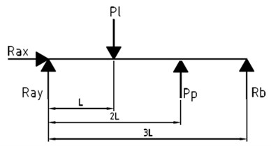
The effectiveness of the algorithm in question was tested on the example of a two-arm model of a loaded machine shaft as shown in Figs. 1 and 2.
Fig. 1Scheme of the load on the horizontal plane
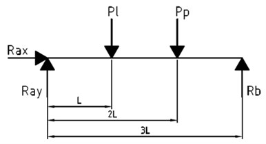
Fig. 2Scheme of the load on the vertical plane
Reactions, bending moment and the desired curvature were determined based on schemes 1, 2. The results are shown in Figs. 4 and 5.
Fig. 3Bending moment
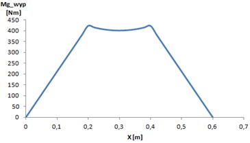
Fig. 4The course of curvature w''
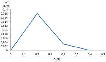
Using the dependence (6) for the values in the plots 3 and 4, there can be determined the shape of the shaft, which under load will achieve desired deflections in the characteristic points (Fig. 5).
Fig. 5Designated outline of the shaft
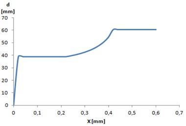
Based on the obtained outline, actual diameters were selected and static simulations were performed. During the calculations the initial expected deflection values were assumed: 0.4 mm, 0.3 mm, where:
– deflection at the application point ,
– deflection at the application of force .
Actual values of deflections for the adopted outline in characteristic points were:
0.3902 mm,
0.2978 mm.
While analyzing the obtained results, it is possible to determine the correctness of the proposed algorithm. The resulting deflections are not higher than expected, which means that the stiffness criterion is fulfilled.
4. Experimental investigations
The experiment was conducted to measure the deflection of the shaft made by 3D printing technology. Based on the method described in the article, the shape of the examined element was chosen (Fig. 6).
Table 1Results of the experiment
Deflection 1 [mm] | Deflection 2 [mm] | Deflection 3 [mm] | Deflection 4 [mm] | Deflection 5 [mm] | Average deflection [mm] | Expected deflection [mm] |
0,94 | 0,97 | 0,91 | 0,92 | 0,95 | 0,938 | 1 |
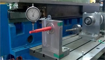
The shaft was made by additive method, attached to the built test bench, the load was applied and the deflection was measured by the clock sensor at the characteristic point. Results (Table 1) were compared with the expected values.
Fig. 6Selected outline of the experimental shaft
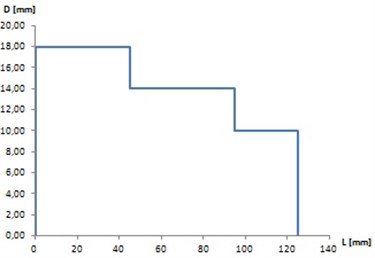
Fig. 7Research stand
5. Conclusions
This paper presents the proposal for the use of complex-valued functions for shaft design based on stiffness criterion. At first, the general characteristics of the problem, the current approach and the concept of the proposed method were presented. The main disadvantage of the classical computational course is the length of calculations. The second chapter presents the use of complex numbers in the case under consideration and the proposed algorithm for designing the outline of the machine shaft. The following chapters present the practical application of the proposed algorithm and preliminary experimental studies.
Conducted considerations indicate the possibility of applying the stiffness criterion for the design of the machine shafts in the case of a spatial load system. The use of complex numbers has eliminated the major obstacle in generalizing the true (2) dependence for flat systems. The application of the complex bend and curvature descriptions enabled the definition of division, which was apparently impossible for vector writing. Performed simulations and preliminary experiments confirm the effectiveness of the proposed method. The differences between the results obtained and the assumed values are small and fall within the permissible ranges. In addition, it should be stressed that the cause of the resulting errors are not only model approximations, but also physical and technical conditions such as the shape of the shaft or dimensional constraints.
The proposed algorithm can be applied primarily in industry, where it is necessary to automate and shorten computational time for typical machine parts and to extend the classical calculation algorithm used for machine shaft design.
References
-
Dąbrowski Z. Machine Shafts. Warszawa, PWN, 2013, p. 20-25, (in Polish).
-
Dąbrowski Zbigniew, Chiliński Bogumił Identification of a model of the crankshaft with a damper of torsional vibrations. Journal of Vibroengineering, Vol. 19, Issue 1, 2017, p. 539-548.
-
Chiliński Bogumił, Zawisza Maciej Analysis of bending and angular vibration of the crankshaft with a torsional vibrations damper. Journal of Vibroengineering, Vol. 18, Issue 8, 2016, p. 5353-5363, https://doi.org/10.21595/jve.2016.17923
-
Chiliński Bogumił, Pakowski Radosław, Stanik Zbigniew Coupled lateral-torsional vibrations of a symmetric rotor. Journal of KONES, Institute of Aviation, Vol. 23, Issue 4, 2016, p. 41-47, https://doi.org/10.5604/12314005.1217187
-
Chiliński Bogumił, Dziurdź Jacek, Zawisza Maciej The analysis of the influence of a torsional vibration damper on transversal displacement of a crankshaft. Journal of KONES, Institute of Aviation, Vol. 23, Issue 4, 2016, p. 33-39, https://doi.org/10.5604/12314005.1217186
-
Dąbrowski Zbigniew, Chiliński Bogumił, Pankiewicz Jarosław A proposition of a torsional-bending vibrations modeling of combustion engines. Journal of KONES, Institute of Aviation, Vol. 23, Issue 4, 2016, p. 71-77, https://doi.org/10.5604/12314005.1217191
-
Dąbrowski Zbigniew, Chiliński Bogumił Influence of torsional-bending coupling on transverse vibration of piston engine. Vibrations in Physical Systems, Vol. 27, 2016, p. 75-82, https://doi.org/10.5604/12314005.1217191
About this article

