Abstract
The dynamic characteristics of reciprocating compressor with clearance between crankshaft and connecting rod were studied. The clearance was regarded as massless virtual link and the dynamics model was established by using Lagrange equation. The variation law of displacement, velocity and acceleration are analyzed under different clearance and different speed conditions of the slider. No-load and load of reciprocating compressor motion were studied. through the phase diagram and the maximum Lyapunov index method. It is found that chaos generally exists reciprocating compressor with clearance between crankshaft and connecting rod and the piston force makes the chaotic motion more intense.
1. Introduction
Reciprocating piston compressor is mainly used for compressing and conveying gas, which is widely used in petroleum and chemical industry. Due to the complex structure and the large number of excitation sources, it is necessary to make a thorough study on the clearance effect of reciprocating compressor. The main moving mechanism of reciprocating compressor is crank slider mechanism. Dynamic analysis of the mechanism with rotation joint clearance and translational joint clearance has been investigated by many researchers analytically and experimentally over the last few decades.
Dubowsky [1, 2] presented impact pair model that it need not complex analysis and calculation to predict the effect of clearance. Flores et al. [3-5] applied the hydrodynamic theory to contact force calculation. when compared dry joint clearances and the lubricated joint, numerical calculation showed that the lubricated joint is closer to actual working condition. Using impact function provided by ADAMS software to establish contact force model for numerical simulation. A set of experimental devices is designed by Khemili and Romdhane [6] and the experimental data are compared with the Adams simulation data. The conclusion of the suspension effect of the flexible rod is obtained. The wear phenomenon was studied and quantified by the Archard 's wear model to develop a revolute clearance joints model. Numerical results show that the distribution of joint clearance is non-uniform due to the contact force [7-9].
The main goal of this work is to study the chaotic dynamic analysis of reciprocating compressor with a clearance on the joint of crank and rod, which is modeled as a massless virtual link and continuous contact mode. In the first place, a simplified model of reciprocating compressor is built using Lagrange method. Subsequently, dynamic simulations of the simplified model are discussed, and numerical results are compared with the without clearance. Furthermore, the effect of the rotational velocity of crank is discussed on the mechanism. Finally, the stability of the motion is studied using Lyapunov exponents.
2. Reciprocating compressor model with a clearance between connecting rod and crank
2.1. Joint clearance model
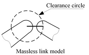
There are three common revolute joint clearance models: massless rod model, two state models, and three state models. The latter two models need to determine the contact stiffness and damping coefficient, but these coefficients are difficult to determine in practice. The amount of wear is very small at the beginning of operation. Wear powder and lubricating oil in the clearance, which make the journal and bearing has been in contact most of the time, so this paper adopts massless link model. Massless link model was used to assess the existence of chaos in a four-bar mechanism by Seneviratne and Earles [10].
Fig. 1Examples of models for revolute joints with clearance
2.2. Reciprocating compressor mechanical equation with a clearance between connecting rod and crank
The action of the air valve, cylinder and so on is the piston force, and the main motion mechanism is the crank slider mechanism, as shown in Fig. 2. The vector diagram of the mechanism is shown in Fig. 3. Since the clearance is regarded as a massless link model, the mechanism adds one degree of freedom.
Fig. 2Schematic representation of reciprocating compressor with a joint clearance
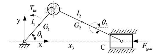
Fig. 3Vector representation of reciprocating compressor with a joint clearance

Fig. 2 is the schematic diagram of the mechanism with clearance. The crank shaft of the reciprocating compressor is represented by , and the angle between the crank and horizontal direction is expressed by , and the angle between the rod and the horizontal is expressed by and the crosshead is represented by the slider. The center of mass of crankshaft, the connecting rod and the crosshead are respectively. The model assumes that the crankshaft rotates at a constant speed.
Using the Lagrange equation method, the system with two degrees of freedom, the crank angle and the displacement of the piston as generalized coordinates, a kinetic equation of the crankshaft and connecting rod mechanism with rod bearing clearance are calculated:
where is the kinetic energy of the system and is the potential energy of the system, is the non-conservative generalized force corresponding to the generalized coordinate .
The dynamic equations are simulated by Simulink toolbox in Matlab software. After debugging and running, the characteristic response is simulated, and the characteristic rules are discussed and analyzed by simulation results.
3. Results and discussions
The objective of this section is to discuss how the joint clearance and the crank rotation speed affect the dynamics performance of reciprocating compressor. The compressor studied in this paper is 2D12 type compressor, and the specific parameters refer to [11].
3.1. Simulation and validation at different driving speeds
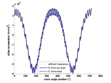
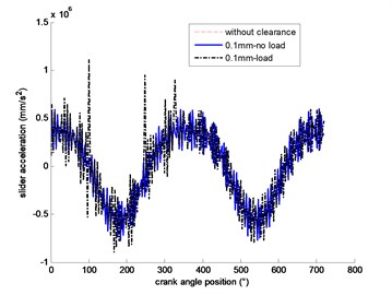
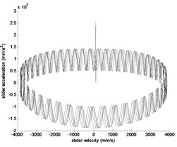
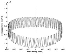
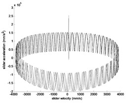
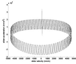
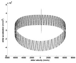
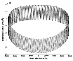
The model is selected as the case study to investigate the dynamic characteristics of the mechanism with the joint clearance at different driving speeds. As shown in Fig. 4, the rotational speeds are 300 rpm, 360 rpm, 480 rpm and 600 rpm respectively and the clearance size is 0.1 mm.
Fig. 4Slider acceleration at different driving speeds: a) 300 rpm; b) 360 rpm; c) 480 rpm; d) 600 rpm
a)
b)
c)
d)
It can be seen from Fig. 4 that in the case of 0.1 mm clearance, the greater the crank speed is, the greater the impact on the acceleration of the slider. The effect of load is more significant than that without load.
3.2. Influence of clearance size
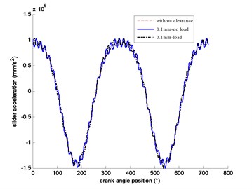
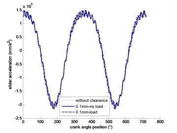
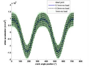
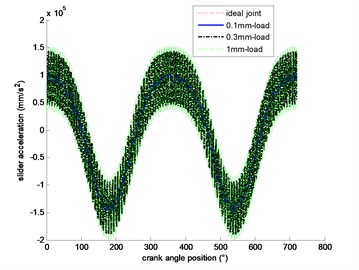
Fig. 5 can be seen that when the crank rotates at 300 rpm speed, the greater the gap, the greater the acceleration of the slider. The effect of load is more significant than that without load.
Fig. 5Slider acceleration at different clearance size: a) 300 rpm (no load); b) 300 rpm (load)
a)
b)
4. Nonlinear dynamic judgement of the system
According to the dynamic analysis of systems with clearance, it is easy to draw phase space and calculate maximum Lyapunov exponent.
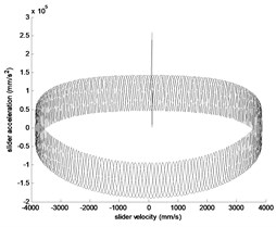
Fig. 6Phase diagram of the system
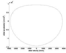
a) 300 rpm, 0
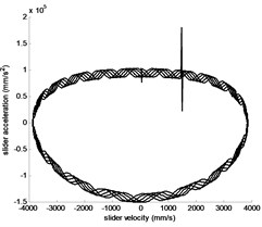
b) 300 rpm, no load, 0.1 mm
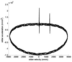
c) 300 rpm, load, 0.1 mm
d) 300 rpm, no load, 0.3 mm
e) 300 rpm, load, 0.3 mm
f) 300 rpm, no load, 1 mm
g) 300 rpm, load, 1 mm
h) 360 rpm, load, 0.3 mm
i) 480 rpm, load, 0.3 mm
j) 600 rpm, load, 0.3 mm
It can be seen from the phase diagram that with the increase of clearance and the increase of crank rotation speed, it exhibits chaotic behavior is possible. Under the action of load, chaos is more violent.
The positive and negative of the largest Lyapunov exponent is the sign to distinguish the periodic solution and the chaotic solution. In this paper, the value of maximum Lyapunov exponent are calculated by Wolf method in different states of system. The value of Fig. 6(b) calculated is 0.0125, and the value of Fig. 6(e) is 0.0164, and the value of Fig. 6(j) is 0.0213.
5. Conclusions
With the continuous operation of reciprocating compressor, the joint clearance will not only increase, but also affect the working performance and failure of reciprocating compressor when it increases to a certain extent. The dynamic behavior of a simplified model with different speeds and clearances is analyzed in this work. Numerical results show that the influence of these parameters should be paid attention to and considered in the fault diagnosis and design process of compressors.
References
-
Dubowsky S. On predicting the dynamic effects of clearances in planar mechanisms. Journal of Engineering for Industry, Vol. 96, Issue 1, 1974, p. 317-323.
-
Dubowsky S., Norris M., Aloni E. An analytical and experimental study of the prediction of impacts in planar mechanical systems with clearances. Journal of Mechanical Design Vol. 106, 1984, p. 444-451.
-
Flores P., Ambrosio J., Claro J. C. P. A study on dynamics of mechanical systems including joints with clearance and lubrication. Mechanism and Machine Theory, Vol. 41, 2006, p. 247-261.
-
Machado M., Costa J., Seabra E., Flores P. The effect of the lubricated revolute joint parameters and hydrodynamic force models on the dynamic response of planar multibody systems. Nonlinear Dynamics, Vol. 69, Issues 1-2, 2012, p. 635-654.
-
Flores P., Ambrósio J., Claro J. C. P., Lankarani H. M. Spatial revolute joints with clearance for dynamic analysis of multibody systems. Proceedings of the Institution of Mechanical Engineers, Part K: Journal of Multi-body Dynamics, Vol. 220, Issue 4, 2006, p. 257-271.
-
Khemili I., Romdhane L. Dynamic analysis of a flexible slide-crank mechanism with clearance, European Journal of Mechanics – A/Solids, Vol. 27, 2008, p. 882-898.
-
Flores P. Modeling and simulation of wear in revolute clearance joints in multibody systems. Mechanism and Machine Theory, Vol. 44, 2009, p. 1211-1222.
-
Tian Q., Xiao Q., Sun Y., Hu H., Liu H., Flores P. Coupling dynamics of a geared multibody system supported by elasto hydro dynamic lubricated cylindrical joints. Multibody System Dynamics, Vol. 33, 2015, p. 259-284.
-
Zhang Z., Xu L., Flores P., Lankarani H. M. A Kriging model for the dynamics of mechanical systems with revolute joint clearances. Journal of Computational and Nonlinear Dynamics, Vol. 9, Issue 3, 2013, p. 1-13.
-
Seneviratne L., Earles S. Chaotic behaviour exhibited during contact loss in a clearance joint of a four-bar mechanism. Mechanism and Machine Theory, Vol. 27, 1992, p. 307-321.
-
Zhao H. Y., Xu M. Q., Wang J. D., Li Y. B. A parameters optimization method for planar joint clearance model and its application for dynamics simulation of reciprocating compressor. Journal of Sound and Vibration, Vol. 344, 2015, p. 416-433.
About this article

This work was supported by National Natural Science Foundation of China (51575331).
