Abstract
The lightweight constructions are nowadays often based on composite materials. The best benefits are possible to obtain especially with a dispersion in the form of long fibres. In this study, the main properties of two almost identical composite rods manufactured from preimpregnated carbon fibres using two different methods will be compared. The first one is called “wrapping” which is helical layering of one wide tape in each ply. The main benefit of this method is good quality of final parts, but we are limited only by straight shapes. The second way “winding”, it is simultaneous deposition of several thinner fiber filaments. This method could handle the problem of curved shapes and fluently variable cross-sections. The disadvantage of this method is imperfect alignment of the placed fibers. This could be caused by a significant tortuosity and stickiness of the individual fiber strands. The goal of the carried work was to experimentally compare the vibrational transfer of these two almost identical rods with the same structure of layers, weight and curing parameters. Based on the certified properties of the base fibres and known boundary conditions, the material model and simulation of the vibrational response was created. The results of the empirical model compared with the experimental on the wrapped part were in good agreement. However, the use of this model also for the wound tubes is questionable, because of the found differences in natural frequencies and a shape of the transfer function. As part of the analytical study also the sensitivity analysis on the mesh quality has been done. As the conclusion is possible to say, that for determination of the main modes the mesh in a solved model could be just standard – it means without visible defects. Changes in the results achieved by improving the mesh quality are just really small. The more significant problem is that with using the contemporary knowledge and methods, it is not possible to simply create analytical model of the wound parts. The only option is trying to adjust the mechanical properties of base materials according to the empirical results.
1. Introduction
In recent years using of composite materials is still exponentially growing, thanks to the excellent specific strength, possibilities of customizing the properties and achievable weight savings. The use of modern advanced composite materials has gained wide acceptance in the last few decades. Compared to metallic structures, composite laminates offer some unique engineering properties while presenting interesting but challenging problems for analysts and designers [1].
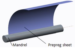
Methods based on epicyclic winding or helical wrapping are generally used for manufacturing of thin-walled composite parts with circular or oval profiles. Those methods are usually used for so-called “wet” form, when bundle of dry placed fibers is impregnated with resin subsequently. Another way is to use of pre-impregnated materials, i.e. prepregs (Fig. 1). Because of their significantly different behavior (sticky, such as double-sided tape), their use is generally limited primarily to manufacturing straight bars. Straight tubes can be produced by so-called wrapping, which is a helical deposition of UD prepreg material in the form of relatively wide tape in several steps and at different angles.
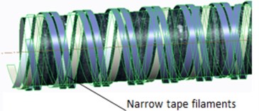
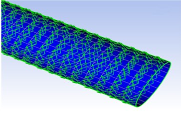
However, in technical practice only the straight bars are insufficient. It is necessary to create parts shaped, dissected and 3-D curved. For this purpose, so-called winding technology in unconventional combination with prepreg materials is used (Fig. 2). This is a process when instead of one wide tape, are around the core placed thin tapes from several coils simultaneously. An advantage of this method is the possibility of its application also for curved shapes. With optimal settings the resulting layer should have the same angle of the fibers, the thickness, the weight and theoretically almost identical mechanical properties (Table 1). During the production of the sample, attention was paid to the aims that composition, number of layers, weight and curing parameters mutually correspond as much as possible.
Fig. 1The way how the fiber material is layered: a) wrapping, b) winding
a)
b)
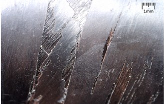
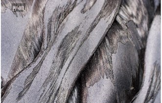
Fig. 2Micropicture of the outer surface of the a) wrapped, b) wound, parts from carbon prepreg
a)
b)
Table 1Specification of the created rods
Layout [deg] | Weight [g] | Thickness [mm] | No. of tapes in 1 ply | Tape width [mm] | |
Wrapped | 55/–55/55/–55 | 163 | 0,8 | 1 | 50 |
Winded | 55/–55/55/–55 | 156 | 0,84 | 10 | 4 |
As the basic, the simplest and simultaneously the most complex way that takes into account the entire spectrum of sub-mechanic parameters for mutual comparison seems to be the vibration test, namely modal analysis. The value of natural frequencies and founded damping characteristics could show us the interrelationship of the basic mechanical parameters of the two compared methods. The stiffness of anisotropic composite plates depends on several factors, i.e. laminate stacking, fiber orientation, surface waviness, number of inner defects [2] and molding temperature. Polymer matrix composites are known to exhibit viscoelastic behavior, which cause energy dissipation and frequency dependence of both stiffness and damping [3, 4]. The problem of dissipating energy in structures such as to reduce the amplitudes of the vibrations is an important feature in mechanical design. Generally, the damping in metal structures is low, which results in high amplitudes of the vibrations. For fibre reinforced composite materials, damping is higher, and it depends on the constitution of the materials [2]. The free vibration of a cantilevered hollow cylindrical solid is investigated based on a general three-dimensional theory of linear elasticity. Usually the classical Euler-Bernoulli beam dynamics theory could be used to analyze this problem. However, more refined theories, often termed “Timoshenko” beam theory, lead to slightly different results, especially at higher frequencies [5, 6]. According to Hung [7] depend the process on the ratio between diameters (dimensions of the actual cross section) and length. In the fundamental vibration mode of these cylinders may be dominated either the longitudinal extension, transverse bending or axial torsional motions. Ben [8] studied methodology for finding material damping properties at higher frequency and at relatively lower amplitudes.
Experimental and analytical characterization of damping is not easy, even with conventional structural materials, and the anisotropic nature of composite materials makes it even more difficult. The techniques for damping measurement often deal with natural frequency or resonant frequency of a system. In general, all apparatus for the investigation of vibration can be categorized as free vibration and forced vibration. Free vibration is a system with the absence of any external input except the initial condition inputs of displacement and velocity [9]. For a forced vibration, a periodic exciting force is applied to the mass. Typical forced vibration techniques include the free-free beam technique and the piezoelectric ultrasonic composite oscillator technique [10].
Kyriazoglou and Guild [11] used the numerical simulations for prediction and comparison of the damping characteristics of long, high strength fibers reinforced polymers laminates. Plagianakos [12] described the dependency of the structure response on the plies orientation, disposition and also stated so called passive damping and marked it as the critical parameter for improving dynamic performance of flexible structures in the point of view of fatigue and aero elastic stability. Sepahvand [13] emphasized that the viscoelastic properties, which have a major effect on the structural damping of the material, are for the polymeric matrix significantly higher than for the conventional materials. However, just the increasing of matrix volume in the fiber reinforced materials has negative impact on the structure stiffness and strength. In his study Sepahvand [13] also emphasized that the thermoplastic matrices exhibit higher damping levels compared to thermosets.
Talbot [14] had tried to describe, whether the laminate theory could be inverted in order to obtain the ply properties direct from the experimental results. Furthermore, he tried to verify whether the approach with thin plate could predict the low frequency vibration with sufficient accuracy. He also emphasized that the elastic constants are very sensitive to variations during the manufacturing process.
2. Used materials
The used semifinished material called prepreg consist of high strength carbon fibers with unidirectional orientation pre-impregnated and pre-saturated by resin. The carbon reinforcement has nominal area weight 150 g/cm2, nominal fiber density 180 g/m3. The content of used epoxy resin was 38 %, with nominal weight 242 g/m2. The cure cycle last 60 min at 120°C. According to conducted measurements and to [15, 16] is the final thickness after polymerization approximately 85 % of the original one (0.36 mm).
The effective design of composite parts is based on the knowledge of stress and strain distribution in the laminate, individual plies and interphases. These values are indispensable for computational models, optimization algorithms, or failure criterias. For reinforced (usually isotropic) material, the matrix of compliance is directly dependent on the main engineering constants. In the classical mechanics application of the Hook’s law for a general, in our case layered type of material in a rectangular coordinate Cartesian coordinate system obtain relation for the so-called ABD (marked just as []) stiffness matrix Eq. (1). [] is the in-plane stiffness matrix, [] means the coupling between in-plane forces and bending moments, [] is the matrix of flexural stiffness and additionally the shear matrix [], which represent the a was also considered. The index “11” indicates the fiber direction and the “22” direction normal to the fiber direction etc. as could be read e.g. [17]. The [] matrix is equal to zero when the laminate layout is symmetrical and then also the in-plane normal shear coupling terms and are zero:
where the laminate stiffness matrix [] is used to express laminate resultant forces per unit width , out-of-plane shear forces and resultant moments per unit width in the terms of laminate normal , shear strains and the laminate mid-plane curvatures . Then the transcription of the stiffness matrix to the shape of the engineering constants [17, 18] and after their quantification for our case is Eq. (2):
3. Experimental investigations
The damping in composites involves a variety of energy dissipation mechanisms that depend on vibrational parameters such as frequency and amplitude and these are studied with nondestructive evaluation [8]. For a cantilever beam subjected to free vibration, and the system is considered as continuous system in which the beam mass is considered as distributed along with the stiffness of the shaft, the equation of motion can be written as Eq. (3) [19]. Free vibration means a system with absence of any external input except the initial impulse [9]:
where, is the modulus of rigidity of beam material, is the moment of inertia of the beam cross-section, is displacement in direction at distance from fixed end, is the circular natural frequency, is the mass per unit length, , is the material density, is the distance measured from the fixed end.
For our case of cantilever beam are the integral constant based on known boundary conditions at the free and clamped point of tube Eqs. (4, 5):
The tested composite tube was mounted with using the segmented prismatic clamping jaws (Fig. 3). The excitation impulse has been done by a modal hammer. Accelerometer Acc1 was using wax stuck near the jaws and at the free end of the tube was stuck the second accelerometer Acc2. Properties of the used accelerometers are, the mass = 1.2 g, maximal sampling frequency 5000 Hz and sensitivity up to 400 g.
The excitation force and its response converted to the frequency spectrum and calculated ratio of these two functions is called the transfer function [4]. In this function does not depend on the type of excitation. It is possible to excite randomly, harmoniously or by an impulse. The results of one type of excitation may be used for predicting response of the structure at a different type [20, 21]. According to [7, 22] the excitation and the response signals are digitalized and processed by an analyzer of signals. Based to the analyzed dynamic response, these methods can be subdivided into modal analysis, frequency domain, time domain and impedance domain.
Fig. 3Scheme of the conducted experiment
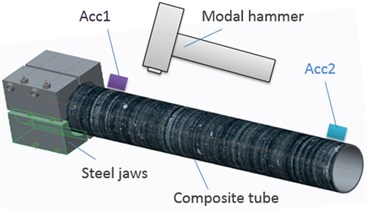
Fig. 4Examples of the acceleration response in the time domain: a) wound, b) wrapped tube
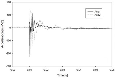
a)
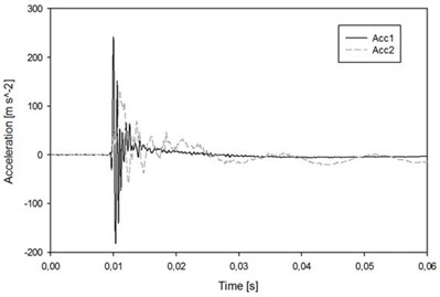
b)
The created experimental data were measured with the maximal frequency 2000 Hz. According to the Shannon-Kotelnik theorem and so-called Nyquist condition Eq. (6) [23], the computational sampling frequency was 5000 Hz:
where [s-1] is the sampling frequency and [s-1] is the highest frequency contained in the signal.
Welch’s overlapped segment averaging estimator was used to estimate the power spectral density Eq. (7) based on the discrete Fourier transformation. The required output is called a transfer function PSD [24]. The function PSD indicates which part of the total transmitted power is carried by a respective frequency:
4. The numerical model
Whitney [21] has from today perspective historically devoted to the description and distribution of stress in individual composite layers and their interfaces. Nowadays the numerical simulations are the indispensable tool without that it is today not possible to efficiently design composite parts. They are necessary when we need to describe the resulting stress and strain through the whole laminate, or even topologically optimize the shape and laminate characteristics. Numerical model analysis allows us to derive the different strain energies stored in the different material directions of the constituents of composite materials [20]. The prediction of the mechanical behavior is a very complex problem, because the process includes stacking sequence, fiber orientation, interface of plies, damage mechanisms etc. In our case, the model of shell composite plate of the specified tube (Table 1) has been carried out in ANSYS ACP preprocessor (Fig. 5). For the standard model, the interlayers between the individual plies were considered as an ideal – it means with the standard mechanical parameters of the used matrix described by the cohesion elements. Here, we used the empirical equation of the deformation properties of the composite materials and the verification of its relationship with the simulation model. The method of face sweep meshing with dominant quadrilateral parts was used. The face edges were parametrically segmented by given number of divisions, and the main mesh was swept through them. There is lots of publications describing layered materials and their simulation [2, 4, 7, 8]. In our case it is possible to find the inspiration in Crawly [3] who tried to compare mesh 6x6 with 5×5 and obtained results that varied in natural frequencies in less than 2 %. This means, that material properties and boundary conditions are for the simulation of not only composite materials more important than just a very fine mesh. This proclamation has been verified by correlation study in the carried numerical model. The desired function was dependency of the Modal frequencies, on the quality of created mesh.
Fig. 5Numerical model: a) the created layout of the reference vectors, b) an example of the deformed shape at the 2nd mode
a)
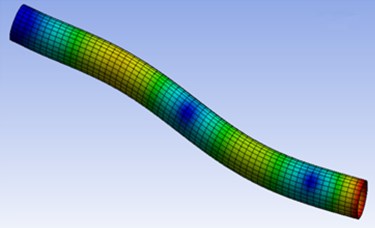
b)
In our case the problem of numerical simulation of composite materials is an assumption of a homogeneous system with perfectly aligned fibers and their uniform distribution throughout the cross section. This idea is commonly applied to the simulation of wrapped and laminated parts. However, how much the results differ for the winding, (i.e. method with large randomness in the fiber alignment or even overlapping filaments – Fig. 2) is a question for comparing the individual results in next chapter. First step of this research has been done in the [16] where by the same way prepared tubes loaded by bending stress were mutually compared with the model. Apart from the measurable differences in both tubes and the model behavior, also the importance of the base model element has been found (Fig. 6). The solid material is appropriate especially from the point of view to the subsequent post processing, interlaminar delamination, failure criteria etc. In contrast the shell is better especially in the point of view of better convergence during the solution, especially for a contact tasks. However, for contact between solid and shell could be this advantage achieved only with a very precisely defined advanced contact formulation.
First step of the simulation was to conduct the modal analysis. The second part of the created model was to find the transfer function. This was done as the harmonic response of from one side clamped tube. The excitation force was acting at the free end of the cantilevered tube in the defined interval 0-2500 Hz. The mode superposition method that consider the mode shapes from the modal analysis to calculate the structure’s response was used. Advantages of this methods are especially the faster solution and in case of more complicated task, the solutions to be clustered about the structure’s natural frequencies. This results in a smoother, more accurate tracing of the response curve.
Fig. 6Two tested approaches for the simulated model: a) solid part, b) layered shell
a)
b)
5. Results and discussion
The experimental results for the wrapped parts and numerical model are in a good agreement as could be seen in the Table 2. The difference increasing in the higher modes (IV, V) which are values, that in the technical practice are not too commonly considered. It is possible to say that the determination of resonant zones based on the numerical model of layered plate is possible. When assessing the second test case, winded parts, i.e. not the one wide tape but 10 segments of relatively narrow filaments are the found values significantly different. So, we could say that the model results for winded parts are rather informal. It is obvious that in terms of numerical simulation the model must be modified. In the first step is possible to try change the definition of input materials. It means do not use the verified material model [4] of the ideal UD tape but homogenize the new tape by charging the all occurring defects, pores and overlapping. All this phenomenon generally cause one thing, decreasing of the main engineering constants, especially the E1 modulus defining the fiber direction strength. The experimentally found PSD functions are shown in the Fig. 7.
Fig. 7The power spectral density function of the: a) wound, b) wrapped tubes
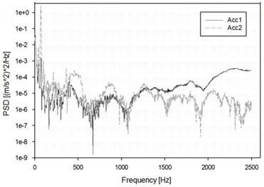
a)
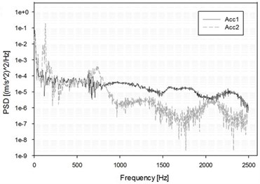
b)
Fig. 8The resulting transfer functions for the: a) wound tubes, b) wrapped
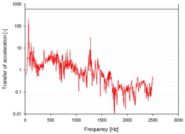
a)
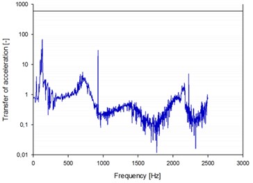
b)
Fig. 9The graph with founded experimental results for: a) wound, b) wrapped parts in graphs without logarithmical scales
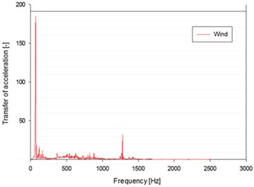
a)
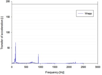
b)
Fig. 10The resultant transfer function from the FEM model: a) linear, b) logarithmical
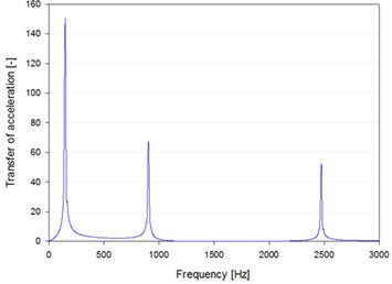
a)
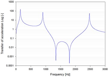
b)
The resultant transfer functions for the both tubes could be seen in the Fig. 8 and Fig. 9.
In the Fig. 10 it is possible to see, the resulting transfer function of the simulated layered part with linear and logarithmical scale for better overview. As has been already mentioned, with the standard software tools, it is not possible distinguish between the model of wrapped or wound geometry, because they should be theoretically the same. Therefore, in the real case we need to take the real difference in the account adjusting the individual material models, depends on the carried experiments. In the Table 2 there is a final comparison between the numerical/experimental results.
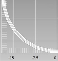
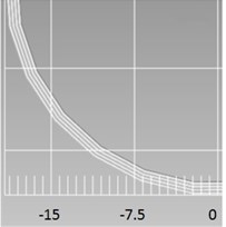
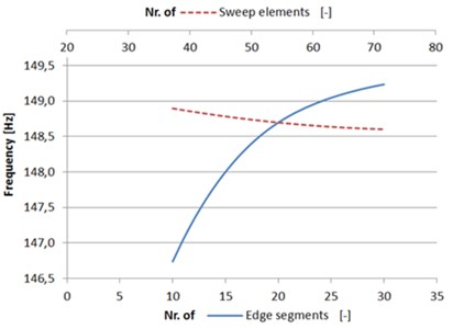
As had been mentioned in the chapter model, the mesh quality depends on two parameters. One was the number of faces divisions and the second on the internal pitch of sweep divisions. The correlation between the mesh size and values of individual modes has been sought. Intervals within the variable parameters laid were <10, 30> for the face and <40, 80> for the sweep. In the table. There are results of the values of the numerically obtained modes in dependency on the mesh size. In Fig. 11 there is the carried parametrical study of randomly chosen 1st mode for illustration of the sensitivity to the mesh quality, which is a common task in scientific works. The values of the frequency with various mesh quality could be seen in the Table 3. It is possible to say that in our case of relatively simple geometry, does not the mesh stats fundamental impact.
Table 2The results of experiment and simulation
Mode No. | I | II | III | IV | V |
Model Shell [Hz] | 147 | 908 | 2294 | 2484 | 3009 |
Model Solid [Hz] | 146,9 | 907,3 | 2294,6 | 2492,6 | 3592 |
Exp. Wrapp [Hz] | 130 | 927 | 2240 | – | – |
Exp. Wind [Hz] | 80 | 1280 | – | – | – |
Mode type [–] | Bending | Bending | Longitudinal | Bending | Torsion |
Table 3Correlation between the individual modes frequency and mesh stats
Mode | I | II | III | IV | V | Time |
Mesh | Frequency [Hz] | relatively | ||||
10×30 | 147,2 | 906,0 | 2296,3 | 2487,0 | 3105,7 | 1,0 |
15×40 | 147,6 | 908,8 | 2294,3 | 2484,6 | 3009,1 | 1,3 |
20×50 | 148,7 | 912,8 | 2291,8 | 2485,6 | 2785,0 | 1,9 |
25×60 | 149,0 | 913,1 | 2289,9 | 2479,9 | 2667,8 | 2,7 |
Fig. 11Sensitivity of the 1st mode value on the mesh quality: a) spatial, b) 2D graph
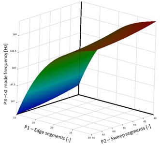
a)
b)
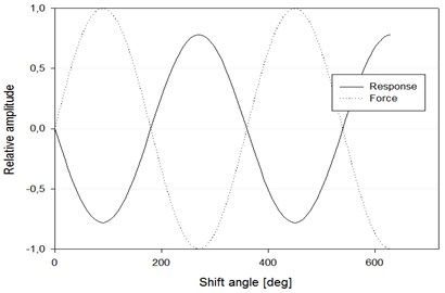
The last founded result is the phase shift between the excitation force and the system response, as could be seen in the Fig. 12.
Fig. 12The phase shift between the acting force and response output
6. Conclusions
The work mainly consisted in the study of modal characteristics. Based on this parameter it is possible to explore all the fundamental mechanical parameters of structural parts, and of thin-walled composite rods in our case. There were two samples, one was made by wrapping and the other one by winding of pre-impregnated carbon tape. After the wrapping with a wide tape, the surface was very smooth, and the material had good quality and homogeneity of material characteristics. The model and the experimental results were in a sufficient agreement. However, the main lack of this method is possibilities of using it for manufacturing of only straight or conical shapes. This is from the point of view to the current technical requirements to part complexity insufficient. Therefore, we tried to use an unconventional method, winding of pre-saturated materials. This method allowed for the creation of curved shapes by using, instead of one large tape, 10 narrow strips. The main disadvantage of this method is that the fibers are not always aligned perfectly as it is for wrapping, and this mean that in many places there is mutual overlapping that form defects of the structure and characteristics of the material. This is reflected by the fact that the mechanical characteristics calculated differ quite a lot from the calculated results. Another significant difference are orderly higher forces acting on the winding device and the rotational frames, caused by the higher friction and mutual stickiness of the tapes.
The experimental results of wound and wrapped tube showed the real existing differences. Even if the tubes should be theoretically the same, the wound one showed higher stiffness. This could be caused by higher preloading and also twisting or overlapping of the thin tapes.
The results founded based on the numerical model, were in a good agreement with the wrapped part. There it is possible to state, that the numerical mode could substitute the experiment. This, especially in the phase of the evaluation of concept could significantly reduce the costs to the prototype models and experiments. However, for composite parts will be the error resulting of the simulation every time bigger than for isotropic materials (e.g. steel parts). This is caused by many parameters and conditions, that we have to consider during the part creation (grease, pressure, temperature, imperfect vacuum, real thickness of plies) and this fact, whether we like it or not, will almost always significantly affect the final mechanical parameters. There is also necessary to choose the appropriate approach how to carry the model. Whether as the solid, or shell parts. Even if the founded values in our case of modal study are almost the same, there are more side bands for the solid model. Very important could this approach be, e.g. in simulation of phenomenon’s with significant interlaminar stresses, like in the case of bending. Advantages of the shell elements are especially in the faster solution and easier model creation. In the chapter based on model, also the quality of the mesh in dependency on the results has been assessed. Our results agreed with [15], who mentioned big importance of precise measurement of the material properties also in various temperature depend behavior and significant dependency on the manufacturing conditions, not only the often even a senseless pursuit to improve the mesh quality.
For the future work, it would be interesting to be compensate the real differences in inner structure by changing the main material model. The second possibility, although more complicated is to use sophisticated CAD model consisting individual strips (Fig. 1(b)) and fill the empty space around with resin and define it as a layered solid model. The last idea is to disrupt the model of the helical sweeps using a pseudo random noise, which should properly represent the real case of arising defects. Then, try to solve the entire model as a composite solid with all of the fibers, resin and defects, instead of the individual idealized plies.
References
-
Kherredine L., Gouasmi S., Laissaoui R., Zeghib N. E. Evaluation and measurement of the damping properties of laminated CFRP composite plates. IOP Conference Series: Materials Science and Engineering, 2012.
-
Berthelot J. M., Assarar M., Sefrani Y., Mahi A. El. Damping analysis of composite materials and structures. Composite Structures, Vol. 85, Issue 3, 2008, p. 189-204.
-
Cawley P., Adams R. D. J. The predicted and experimental natural modes of free-free CFRP plates. Composite Materials, Vol. 12, 1978, p. 336-347.
-
Kulhavý P., Petřík J., Srb P., Lepšík P. Vibration response of composite structures. Experimental Stress Analysis, 2016.
-
Parks D., Anand L. Mechanics and Materials II. Massachusetts Institute of Technology Department of Mechanical Engineering, 2004.
-
Vozkova P. Multiscale Modeling of Mechanical Properties of Textile Composites. Disertation Thesis, Liberec, Technical University of Liberec, 2008.
-
Hung K. C., Liew K. M., Lim M. K. Free vibration of cantilevered cylinders: effects of cross-sections and cavities. Acta Mechanica, Vol. 113, 1995, p. 113-137.
-
Bena B. S., Bena B. A., Adarsh K., Vikram K. A. and Ratnamd Ch. Damping measurement in composite materials using combined finite element and frequency response method. International Journal of Engineering Science Invention, 2010, p. 89-97.
-
Botelho E. C., Pardini L. C., Rezende M. C. Damping behavior of continuous fiber/metal composite materials by the free vibration method. Composites Part B: Engineering, Vol. 37, 2006, p. 255-264.
-
Guan H., Gibson R. F. Micromechanical Models for Damping in Woven Fabric-Reinforced Polymer Matrix Composites. Journal of Composite Materials, Vol. 35, Issue 16, 2001, p. 1417-1434.
-
Kyriazoglou C., Guild F. J. Finite element prediction of damping of composite GFRP and CFRP laminates-a hybrid formulation-vibration damping experiments and Rayleigh damping. Composite Science Technology, Vol. 67, 2007, p. 2643-2654.
-
Plagianakos T. S., Saravanos D. A. High-order layer wise mechanics and finite element for the damped dynamic characteristics of sandwich composite beams. International Journal of Solids Structure, Vol. 41, 2004, p. 6853-6871.
-
Sepahvand K. Stochastic finite element method for random harmonic analysis of composite plates with uncertain modal damping parameters. Journal of Sound and Vibration, Vol. 400, 2017, p. 1-12.
-
Talbot J., Woodhouse J. The vibration damping of laminated plates. Composites Part A: Applied Science Manufacturing, Vol. 28, 1997, p. 1007-1012.
-
Lepoittevin G. Composite Laminates with Integrated Vibration Damping Treatments. Dissertation Thesis, ETH Zurich, 2012.
-
Kulhavy P., Lepsik P. Study of bending properties of thin walled carbon and flax composite rods winded of prepreg fibers. Experimental Stress Analysis, Slovakia, 2017.
-
Kaw K. Mechanics of Composite Materials. Second Edition, Taylor and Francis Group, United States of America, 2006.
-
Jones R. M. Mechanics of Composite Materials. Taylor and Francis, United States of America, 1998.
-
Meirovitch L. Analytical Methods in Vibrations. Prentice Hall (a Pearson Education Company), New Jersey, United States, 1967, p. 576.
-
Zou Y., Tong L., Steven G. P. Vibration based model dependent damage identification and health monitoring for composite structures. Journal of Sound and Vibration, Vol. 230, 2000, p. 357-378.
-
Whitney J. M. Shear correction factors for orthotropic laminates under static load. Journal of Applied Mechanics, Vol. 40, 1973, p. 302-304.
-
Piersol A. G. Harris’ Shock and Vibration Handbook. 6th Ed., Mc-Graw Hill, New York, 2010.
-
Lee D. G., Kosmatka J. B. Damping analysis of composite plates with zig-zag triangular element. AIAA Journal, Vol. 40, Issue 6, 2002, p. 1211-1219.
-
Birman V., Byrd L. W. Analytical evaluation of damping in composite and sandwich structures. AIAA Journal, Vol. 40, Issue 8, 2002, p. 1638-1643.
About this article

This publication was written at the Technical University of Liberec as part of the project “Innovation of technical systems structures with the use of composite materials” with the support of the Specific University Research Grant, as provided by the Ministry of Education, Youth and Sports of the Czech Republic in the year 2017.
