Abstract
The seismic isolation techniques of controlled rocking bridge pier is presented to improve seismic performance of the railway bridge in the earthquake-prone zone. In order to limit the lateral movement and overturning under the rarely strong earthquake, the inhibiting steel bar and prestressing tendon are used in the rocking bridge piers. The seismic performance of the two-different controlled rocking bridge piers are evaluated by quasi-static tests for two 1/10 scale model piers of a typical railway bridge pier with pile foundation. Through the hysteretic behaviors, it can be concluded that the rocking isolation model pier with the inhibiting steel bar shows better energy dissipation capacity, while the rocking isolation model pier with the prestressing tendon has higher anti-overturning capacity under strong earthquakes.
1. Introduction
In early days, it is common to improve the earthquake resistance of the bridge structures by increasing their own strength in the earthquake-prone zone. However, it is not economical and applicable to satisfy the seismic requirement of bridges by using the large-size components. The rocking isolation system is a new effective technique to reduce the seismic energy for bridges, for instance, the bridge pier can be designed to rock on beam or foundation surfaces during the attacks of a strong earthquake [1]. Mergos and Kawashima [2] found that inelastic rocking of bridge pier has a significant isolation effect on the seismic response of the bridge. In recent years, many relevant experimental and numerical researches on the rocking seismic isolation mechanism have been carried out around the world [3-6]. It can be concluded that bridges with rocking foundations have advantages in seismic performance compared with other bridges, such as the fixed-base or the hinging-column bridges [7, 8].
The previous researchers have paid much attention on the seismic isolation for spread or shallow foundation of bridges, but very few researches are focused on the seismic isolation of bridge pier with pile foundation. Therefore, it is essential to present a rocking seismic isolation technique for bridge pier with pile foundation to dissipate energy during a strong earthquake. In this study, two different controlled rocking techniques with inhibiting steel bar and prestreesing tendon for bridge pier with pile foundation are adopted in order to limit the lateral movement and overturning under the rarely strong earthquake. Quasi-static tests for two 1/10 scale model piers of a typical railway bridge pier with pile foundation are performed to investigate the seismic performance of the two rocking seismic isolation of bridge pier. The hysteretic curves and skeleton curves are obtained and analyzed to evaluate the effect of the rocking seismic isolation.
2. Experimental design
2.1. Design of the controlled rocking model piers
The typical railway bridge pier with 24 m-span simply supported T-beam is selected as prototype, its height is 12 m. The concrete of the bridge pier is C30 (cubic compressive strength of 30 MPa). The bridge pier has a longitudinal steel ratio of 0.15 %, the diameter of the pile is 1.25 m, and its reinforcement rate is 0.6 %. According to the similarity relation between the prototype and the model pier, the size of the model pier is shown in Fig. 1. Two 1/10 scale model piers are designed, the model 1 is the rocking pier controlled with the inhibiting steel bar at the pier footing to make the pier basement and the pile cap work together (see Fig. 2(a)). The model 2 is designed with controlled rocking isolation by using the prestressing tendon throughout the center of the pier, its basement and the pile cap, as shown in Fig. 2(b).
Fig. 1Schematic diagram of the model pier
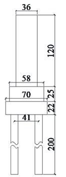
a) Front view
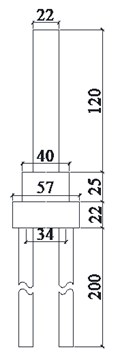
b) Lateral view
Fig. 2Schematic diagram of two different controlled rocking seismic isolation bridge piers
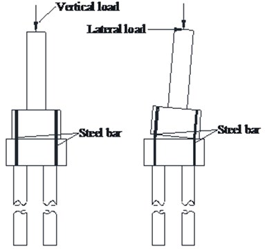
a) Controlled rocking with inhibiting steel bar
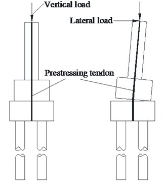
b) Controlled rocking with prestressing tendon
2.2. Materials of the model piers
The model pier, pile cap and pile foundation are casted by C30 concrete. In order to determine the actual concrete compressive strength of the model pier, the concrete cube specimen are maintained in the same external environment with model piers. The 28 days compressive strength of the concrete cube specimen (100 mm×100 mm×100 mm) is tested according to the relevant specifications, and the test results are shown in Table 1.
The bridge pier and pile foundation is reinforced by the plain steel bar with a diameter of 6 mm, the steel bar is the standard model of HPB235. The mechanical properties of the steel bar with a diameter of 6 mm are shown in Table 2.
Table 1Strength of compressive strength of concrete cube specimen
Specimen | Concrete age / d | Fracture load / kN | Tested strength / MPa | Calculated compressive strength / MPa |
1# | 28 | 320 | 32.0 | 29.7 |
2# | 28 | 312 | 31.2 |
Table 2Mechanical properties of reinforcement steel bar
Specimen | Elastic modulus / GPa | The yield strength / MPa | The yield strain | Ultimate strength / MPa | Ultimate strain |
1# | 207 | 238 | 0.0011 | 367 | 0.141 |
2# | 209 | 248 | 0.0011 | 375 | 0.153 |
The ground soil used in geotechnical model tank is loess. The soil was crushed firstly, and then evenly wetted. This process can be repeated several times to make the soil close to its optimal water content. The soil is consolidated by layers according to the requirement of the related codes in China. At the same time, the physical and mechanical properties of the foundation soil are tested by cut ring and triaxial apparatus, and the results are shown in Table 3.
Table 3Physical and mechanical properties of foundation soil
Cut ring method | Static triaxial test | |||
The water content / % | Wet bulk density / g·cm-3 | Deformation modulus / MPa | Cohesive force / kPa | Angle of internal friction / ° |
11.8 | 2.0 | 25.0 | 58.5 | 32.0 |
2.3. Testing apparatus and method
The test apparatus consists of a horizontal loading system, a vertical loading system, and a data acquisition system. The horizontal loading system is controlled by the electro-hydraulic servo loading method. The servo hydraulic jack, which is installed on the reaction wall, has a loading capacity of 500 kN, and the maximum stroke is ±200 mm. The vertical loading system is a carrying pole beam device, which is mainly composed of a rigid beam, sling belt, sand bags filled with steel grit and its bearing device. The vertical loading is adjusted by the weight of sand bags. The test apparatus is shown in Fig. 3.
Fig. 3Configure of the test apparatus and its loading system
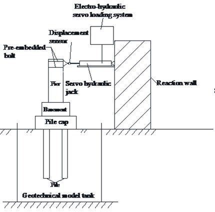
a) Horizontal loading system
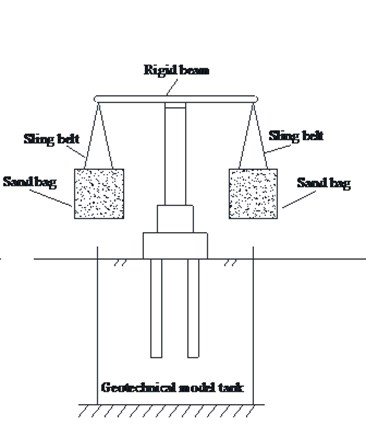
b) Vertical loading system
3. Results analysis
3.1. Hysteresis characteristics
The lateral load-displacement hysteresis curves of the two model piers during the quasi-static testing process are shown in Fig. 4(a) and (b). It can be seen that the hysteresis loop shape of Model 1 changes with the increase of applied lateral load (see in Fig. 4(a)). At early cyclic loading stage, hysteresis loops show a spindle shape, which indicates that the pier has energy dissipation in this stage. At later cyclic loading stage, the shape of hysteresis loops shows a shrinkage compared to that at early loading stage, which is related to the slippage and lifting of the pier from basement. The area of the hysteresis loop shows that there is still some energy dissipation at later loading stage, which is due to the plastic deformation and friction of the two-added inhibiting steel bar. The hysteretic loops of the model 2 show a reversed Z-shape, the area of the hysteretic loop is smaller than the model 1, which indicates that the energy dissipation of the rocking pier with prestressing tendon is not very well. However, from the larger displacement, it can be found that the deformation capacity is high for the model 2 due to the high strength of the prestressing tendon.
Fig. 4Hysteresis curves of the two model piers
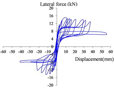
a) Model 1
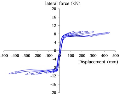
b) Model 2
3.2. Skeleton curves
The skeleton curve is one of the important data for evaluating the seismic performance of the structure, which can be determined by the hysteresis curves under cycle loading. The deformation capacity, energy dissipation capacity, strength and stiffness degradation of structures can be deduced from the skeleton curve.
Fig. 5Skeleton curves of the two model piers
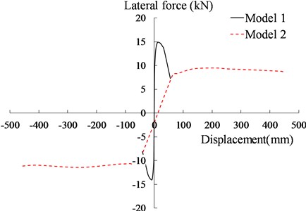
The skeleton curves of the two-model pier are determined by the peak value of the loading loops, as shown in Fig. 5. From the skeleton curves of the two model piers, it can be concluded that the initial stiffness, the separation load and ultimate load of Model 1 are larger than that of Model 2, which reflects its low anti-overturning capacity under small earthquakes. However, the anti-overturning capacity of the Model 2 are significantly improved due to the prestressing tendon. The rocking bridge pier cannot be overturned even the displacement increases to a relatively large value, which is close to 500 mm in this study.
4. Conclusions
The force-displacement hysteretic curves and the skeleton curves of the two controlled rocking bridge piers with inhibiting steel bar and prestressing tendon were obtained from the quasi-static test results. Some conclusions are drawn through analyzing these cyclic behaviors.
1) The hysteretic loops of the controlled rocking isolation model with inhibiting steel bar (Model 1) change from a spindle shape to a reversed Z-shape and show a high energy dissipation capacity. The hysteretic loops of the controlled rocking isolation model with prestressing tendon (Model 2) show a reversed Z-shape, and their areas are small, which indicates a low energy dissipation capacity, but the deformation capacity is improved significantly.
2) The skeleton curves show that the Model 1 has a low anti-overturning capacity under small earthquakes due to the two-added steel bar (small pier-top displacement). The anti-overturning capacity of the Model 2 are significantly improved due to the prestressing tendon. The rocking pier cannot be overturned even the pier-top displacement increases to a relatively large value, which is close to 500 mm in this study.
References
-
Cheng C. T., Chen F. L. Seismic performance of a rocking bridge pier substructure with frictional hinge dampers. Smart Structures and Systems, Vol. 14, Issue 4, 2014, p. 501-516.
-
Mergos P. E., Kawashima K. Rocking isolation of a typical bridge pier on spread foundation. Journal of Earthquake Engineering, Vol. 9, Issue 2, 2005, p. 395-414.
-
Anastasopoulos I., Loli M., Georgarakos T., Drosos V. Shaking table testing of rocking-isolated bridge pier on sand. Journal of Earthquake Engineering, Vol. 17, Issue 1, 2013, p. 1-32.
-
Leitner E. J., Hao H. Three-dimensional finite element modelling of rocking bridge piers under cyclic loading and exploration of options for increased energy dissipation. Engineering Structures, Vol. 118, 2016, p. 74-88.
-
Li J., Xiang N., Tang H., Guan Z. Shake-table tests and numerical simulation of an innovative isolation system for highway bridges. Soil Dynamics and Earthquake Engineering, Vol. 86, 2016, p. 55-70.
-
Nguyen W., Trono W., Panagiotou M., Ostertag C. P. Seismic response of a rocking bridge column using a precast hybrid fiber-reinforced concrete (HyFRC) tube. Composite Structures, Vol. 174, 2017, p. 252-262.
-
Deng L., Kutter B. L., Kunnath S. K. Probabilistic seismic performance of rocking-foundation and hinging-column bridges. Earthquake Spectra, Vol. 28, Issue 4, 2012, p. 1423-1446.
-
Panagiotou M., Antonellis G. Seismic response of bridges with rocking foundations compared to fixed-base bridges at a near-fault site. Journal of Bridge Engineering, Vol. 19, Issue 5, 2014, p. 644-651.
About this article
This research was supported by the National Natural Science Foundation of China (Grant No. 51268027 and 51768036). On behalf of all authors, the corresponding author states that there is no conflict of interest.
