Abstract
Equipped with rib groove structure, the self-cooled brakes disc enjoys an excellent heat dispersion and are applied in the belt conveyors with good effect. According to Hooke’s Law, the steady-state thermo-mechanical coupling expression of the brake disc under two-dimensional conditions is deduced, and the solving method of the displacement differential equation is given. Based on the ABAQUS, thermo-mechanical coupling finite element model for self-cooled disc brakes is established and for the structure and load characteristics of the brake discs, three different azimuth paths are defined and the transient thermal stress variations under different paths are obtained. Through the thermal cycling tests of self-cooling brake disc samples at 300 °C, 400 °C, and 500 °C under the condition of heat and water-cooling for 800 times respectively and analyzing the metallographic structure with electron probe microscope, the results have showed that a large amount of graphitized tissue can be precipitated under the high circulating temperature and heating cracks can induced.
1. Introduction
Thermal stress is a complex phenomenon that originates from distortions caused by thermal confinement, but is not an isolated phenomenon, and it co-occurs with creep, mechanical fatigue, corrosion, oxidation, and other destructive processes. Thermal stress is usually generated when the free thermal restraining components expands or contracts [1]. For disc brakes, when the brake disc undergoes repeated heating and cooling cycles, structural changes and damages can be induced, inducing changes in the internal structure, causing severe thermal cracking and braking failure in severe cases [2]. During the coal mines production, with the increasing of the carrying capacity of the belt conveyor, higher requirements have been put on the performance of the braking system. As a new type of brake equipment, self-cooled disc brakes are widely used and recognized in belt conveyors and other coal transportation equipment [3].
Numerical simulation and metallographic analysis are the most direct and effective methods for studying thermal stress effects. For the working conditions of self-cooled disc brakes, the thermal-mechanical coupling method is used in this paper and the transient thermal stress characteristics of brake discs are studied based on ABAQUS. At the same time, by analyzing the microstructure characteristics of the brake disc under different thermal cycling loads with electron probe microscopy, the thermal fatigue effect has been evaluated and analyzed in order to provide the basis for the optimal design of the braking system. The study of thermal stress characteristics of self-cooling brake discs is of great significance for the safe and efficient production of coal mines.
2. Thermal coupling mathematical models and boundary conditions
2.1. Thermally coupled differential equations
When the belt conveyor brakes, the brake disc generates thermal expansion and thermal stress under the brake pressure of the brake disc. In the Cartesian Coordinate System , assuming that the self-cooling brake disc is an ideal thermoelastic body [4], the temperature at each point of the surface is , and the positive strain of the disc body is (where is the thermal expansion coefficient). According to Hooke’s Law, the total strain component expression of the disk mass point is as follows:
where , and are positive strains, , and are shearing strains, , and are positive stresses, , and are shearing strains, is Poisson’s ratio; is elastic modulus.
In order to more conveniently and intuitively express the thermo-mechanical coupling effect of self-cooling disc brakes [5], the Eq. (1) and Eq. (2) are combined and simplified, and the expression in the two-dimensional plane can be obtained as follows:
According to the relationship between stress and strain, Eq. (3) can be transformed into the relational expression of strain and temperature as follows:
Among them, the relationship between stress and strain is:
where and are displacement components in the and directions, respectively.
Then Eq. (4) and Eq. (5) can be converted as follows:
According to the physical properties of the ideal thermo-elastic body, the continuous equation can be expressed as follows:
Then the thermo mechanical coupling differential equations can be concluded as follows:
Eq. (8) is the expression of the steady-state thermodynamic coupling differential equation of the self-cooling brake disc under two-dimensional conditions.
2.2. The solution to displacement differential equations
Since the solution to the differential equations for thermo-mechanical coupling based on the analytical method is very difficult, it is necessary to specify the relational expressions of each displacement component and the heat transfer boundary conditions [6]. In engineering, for the solution of displacement differential equations, a more effective and direct method is needed. The special solutions for displacement differential equations should be introduced, which may not correspond to boundary conditions.
For the convenience of calculation, the displacement potential function can be used as a special solution with its expression as follows:
Substitution of the displacement potential function can be imported into the coupling equation yields as follows:
Since the parameters and are constant physical quantities, Eq. (10) can be expressed as follows:
In the supplementary calculation of the supplementary solution, we can first suppose that the supplementary solutions, and , satisfy the homogeneous differential equation as:
At this point, the stress component under this condition is:
The solution corresponding to the final boundary condition is:
For the solution of thermo-mechanical coupling equations, the finite element method can obtain temperature and displacement solution sets more efficiently and intuitively than analytic methods. If time-varying factors are considered, the transient thermal stress field of the model can be directly derived from the relationship between stress and strain.
3. Numerical simulation of thermal stress
3.1. The establishment of a finite element model
In ABAQUS, the self-cooled disc brake model is established in which the brake pad establishes an equivalent model based on the friction radius and the effective braking area. At present, most of the self-cooled brake discs are made of gray cast iron with good vibration absorption and thermal conductivity. Brake pads matched with brake discs are made of non-metal materials with low coefficient of thermal expansion, high specific heat, and high thermal conductivity, so as to meet the coal mine production requirements of explosion-proof and fireproof spark.
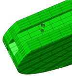
In the definition of physical properties of materials, the characteristics of brake thermal conductivity, specific heat, thermal expansion coefficient and elastic modulus with temperature, as shown in Table 1, are considered and complete the setting of materials through parameter fitting. In the numerical simulation of thermal stress, it is assumed that the material is uniform and isotropic, but the asymmetric plastic behavior of the material during the tension and compression process must be considered. The analysis step is established based on the temperature-displacement coupling analysis type and the pre-processing parameters defined are as follows. (1) Set the total analysis time as 10 s. (2) Set the brake pressure loading time as 1 s. (3) Set the brake pressure as 2.8 MPa. (4) Set the initial angular velocity of the brake disc as 23.2 rad/s. The brake is meshed with a hexahedral mesh, and the ribs are thinned in the radial direction and finally, 18,466 units are obtained, and the number of nodes is 26,430 nodes, as shown in Fig. 1.
Fig. 1Brake meshing
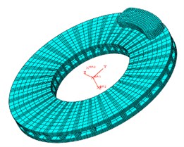
Fig. 2Definition of average heat transfer coefficient
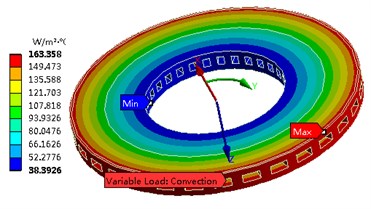
Table 1Self-cooled disc brake material properties
Brake parts | Temperature / °C | Heat conductor coefficient / W·m-1·K-1 | Specific heat / J·kg-1·K-1 | Thermal expansion coefficient / 10-6 K-1 | Elasticity modulus / GPa |
Brake disc | 20 | 42.38 | 503 | 4.39 | 105 |
100 | 43.06 | 530 | 11.65 | 95 | |
200 | 44.23 | 563 | 12.84 | 90 | |
300 | 45.55 | 611 | 13.58 | 90 | |
Brake pad | 20 | 0.8 | 900 | 20 | 0.6 |
100 | 1.04 | 1025 | 28 | 0.58 | |
200 | 1.17 | 1120 | 33 | 0.44 | |
300 | 1.22 | 1210 | 44 | 0.28 |
3.2. Thermal stress solution and analysis
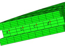
In order to facilitate the study of the dynamic characteristics of thermal stress, three different paths are defined for the structure and load characteristics of the brake disc, as shown in Fig. 3. The transient thermal stress curve under different paths is shown in Fig. 4.
Fig. 3Path definition in different directions
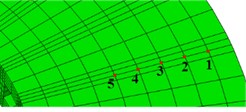
a) Path I
b) Path II
c) Path II
3.3. Test design and installation
From Fig. 4(a), it can be seen that the thermal stress from the end face of the cold brake disc shows a saw tooth increasing phenomenon within the friction radius, which is caused by the instantaneous high temperature of the friction surface and the brake pressure. During the radial direction, the order of thermal stress at the same moment is not in one-to-one correspondence with the radial position of the nodes. Although node 5 is not in the frictional surface, its thermal stress still exhibits some fluctuation due to heat transfer.
Fig. 4(b) shows that the thermal stress on the surface of the fins and the thermal stress on the end face of the brake disc have significant differences in the trend and magnitude of the change and show an instantaneous sudden change because the temperature of the fins is relatively low and compared to the thermal expansion factor [7, 8], the main factor is the instantaneous reduction of the stress caused by the transfer of brake pads; after 1 second, the braking torque is cancelled, and the thermal stress at Node outside the friction radius does not decrease, but gradually increases, which is in contrast to the Node -, because the Node and the direct heat source is a little far and it continues to heat up under heat conduction, making the temperature dominate the thermal stress.
Fig. 4(c) shows that under the effect of brake pressure, the thermal stress of the rib fins in the axial direction does not show a significant difference, but after the brake pressure is relieved, the thermal stress at the top position of the fins is basically maintained. This is because the Node of completes the approximate balance of heat transfer in a shorter time than the Node of .
Fig. 4Transient thermal stress curves in different paths
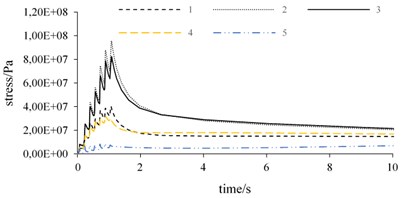
a) Thermal stress curve of path I
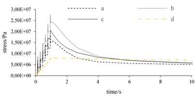
b) Thermal stress curve of Path II
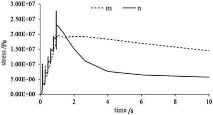
c) Thermal stress curve of path III
4. Microstructure analysis under thermal cycling
Due to the large brake pressure, the instant heat production temperature of the belt conveyor from the surface of the cold brake disc is very high and can reach more than 500 °C, but it will be reduced to 200 °C instantaneously under the effect of heat transfer. With the rotation of the brake disc, the end face is subjected to significant thermal cycling, which will inevitably cause thermal fatigue after long-term work [9].
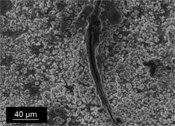
Through the thermal fatigue tester, repeated heating and cooling of the brake disc can be achieved [10]. In the thesis, self-cooled rotor disc specimens have been subjected to thermal cycling tests at 300 °C, 400 °C, and 500 °C with heating and water cooling for 800 times. The samples after thermal cycling were prepared into metallographic specimens and their microstructure was observed with an electron probe microscope, as shown in Fig. 5.
It can be seen in Fig. 5(a) that continuous thermal cycling results in a change in the pearlite structure, which is similar to carbon steel annealing. Thermal cycling promotes the dissolution of cementite and accelerates the dissolution rate of cementite, but the phenomenon of hot corrosion is not yet apparent.
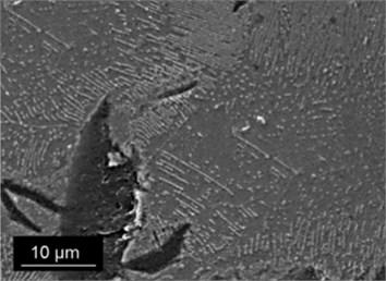
It can be seen in Fig. 5(b) that compared to Fig. 5(a), the morphology of the microstructure has changed significantly, and a small amount of graphite flakes has appeared, which is characterized by a lower hardness. The appearance of graphite flakes is a change in oxygen enrichment, which is the product of a specific corrosion process.
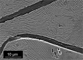
Fig. 5(c) shows that a large amount of graphitized tissue precipitates, which is also a unique form of deterioration of the gray cast iron material, belonging to the partial galvanic corrosion. Graphite corrosion can occur evenly or in a localized fashion, resulting in a series of interconnected pits that can penetrate some or all of the thickness to induce hot cracks, and have severe damages to the mechanical and tribological properties of the material.
Fig. 5Microstructures at different thermal cycling temperatures
a) Thermal cycling microstructure at 400 °C
b) Thermal cycling microstructure at 500 °C
c) Thermal cycling microstructure at 600 °C
5. Conclusions
The results show that the stress variation of the end face on the brake disk is caused by the combination of the instantaneous high temperature of the friction surface and the brake pressure. The stress variation on the surface of the rib fins in the range of friction radius mainly depends on the brake pressure, and the stress variation of the nodes outside the friction radius mainly depends on the interaction between heat generation and heat transfer. When the thermal cycle temperature is higher than 500 °C, graphite flakes begin to appear in the microstructure of the brake disc, and gradually deteriorate with the increasing of temperature, which can induce heat cracking. During the production of coal mines, the heat transfer efficiency of the brake disc can be enhanced by adding external forced ventilation facilities, which can not only effectively extend the working life but also greatly reduce the occurrence probability of hot cracks.
References
-
Dongye S., Fenbin H. Experimental analysis of thermal stress distribution of wet multi disc brake. China Mechanical Engineering, Vol. 16, Issue 8, 2010, p. 2006-2010.
-
Sen Zh, Linjing X. Study on friction thermodynamics of disc brake of miner. Coal Mining Machinery, Vol. 33, Issue 5, 2015, p. 73-75.
-
Xiangzhou Q., Haixin T. Research on transportation brake system based on coal mine motor vehicle. Engineering Technology: Digest Version, Vol. 44, 5, p. 2016-318.
-
Rong F., Fei G., et al. Tribological behavior of copper based composites under dry and wet conditions. Journal of Composite Materials, Vol. 27, Issue 1, 2010, p. 79-85.
-
Zhendong D., Qunji X. Thermodynamic study of friction and wear: current situation and prospect. Chinese Science: Technical Science, Vol. 39, Issue 7, 2009, p. 1211-1215.
-
Dengfeng W., Haitao H., et al. Finite element analysis and test of brake scream of disc brake. Automobile Engineering, Vol. 29, Issue 8, 2010, p. 705-709.
-
Chung W. S., Jung S. P., Park T. W. Numerical analysis method to estimate thermal deformation of a ventilated disc for automotives. Journal of Mechanical Science and Technology, Vol. 24, Issue 11, 2010, p. 2189-2195.
-
Liang L. Research on fast finite element simulation model of brake thermal analysis. Journal of System Simulation, Vol. 32, Issue 12, 2005, p. 1247-1257.
-
Junwang D., Pingping Y., Xiang X. Effect of pressure on friction and wear properties of space docking friction materials. Nonmetallic Ore, Vol. 29, Issue 5, 2006, p. 59-62.
-
Litos P., Honner M., Lanq V. A measuring system for experimental research on the thermomechanical coupling of disc brakes. Journal of Automobile Engineering, Vol. 222, Issue 7, 2008, p. 1247-1257.
About this article

The paper is supported by the Youth Talent Innovation Project (BZXYQNLG201703).
