Abstract
Cold mechanical vibration of air-cooled brake disc is mainly caused by the non-uniform geometry, including disk thickness variation (DTV) and side face run-out (SFR). A mathematical model consisting of the non-uniform geometry is constructed, which is imported into the dynamic brake model established by Lagrange equation as initial parameters. The braking moment fluctuation during braking process is obtained by MATLAB software. The experimental verification is realized based on Link3900 NVH test platform, where result shows that the calculated brake pressure is quite consistent with the test value. By single variable method, the key influence factor that affected braking moment fluctuation is analyzed, including DTV, SFR, friction coefficient, contact stiffness coefficient and damping coefficient. The conclusion shows that reducing these parameters within a certain range can significantly reduce the amplitude of cold vibration, except for the contact damping coefficient.
Highlights
- The mathematical description for the discrete vibration system is put up in brake system with spring-damping method, which is rarely researched.
- The discrete multi-degree-of-freedom vibration system is suitable for the calculation of brake cold vibration, which has important guiding significance for the research and control of noise.
- The hypothesis is verified by Link 3900 NVH experimental machine, and can accurately simulate the braking conditions and obtain data in real time.
- The effect of DTV and SFR is researched, which can provide important basis for structural design and optimization.
1. Introduction
Disc brake is one of the most widely used brakes in automobiles at present. Still, as an important and common problem in disc brakes, cold mechanical vibration is mainly caused by the non-uniform geometry formed by machining, assembly, non-uniform wear and corrosion. It not only has a bad influence on the comfort, reliability and safety of automobiles, but also accelerates the aging and fatigue damage [1] of relevant components of brake system, and increases the cost of quality assurance and maintenance. A large number of tests have shown that the cold vibration of brake belongs to 1-5 order low frequency vibration, generally below 100 Hz. Compared with geometric inhomogeneity, the cold vibration is less easily affected by its own modal or material characteristics, especially these air-cooled disc brakes because of the ventilation slot structure.
As we all know, the mathematical description for the discrete vibration system is quite convenient for spring-damping system research, but rarely mentioned or applied in disc brake system. At present, most of the studies on braking vibration are mainly based on modal analysis [2-5] and noise testing [6-9]. Whether the computation of discrete vibration with multiple degrees of freedom is suitable and accurate for the disc brake cold vibration and noise research is still not quite clear. Therefore, this hypothesis is put forward according to the non-uniform geometry of brake disc that caused by disk thickness variation (DTV) and side face run-out (SFR), and it can be verified by NVH experimental method that designed in the paper.
2. Construction of geometric inhomogeneity model
2.1. Analysis on influence factors of cold vibration
Geometric inhomogeneity of thickness, also known as disk thickness variation (DTV, unit of μm), refers to the thickness difference of brake disc along the circumferential direction, as shown in Fig. 1. In the braking process, the friction equivalent radius will be changed, and the contact pressure distribution will be uneven. At the same time, because the piston in the hydraulic brake system pushes the brake disc close to the rotating brake disc, the uneven thickness of the brake disc will force the piston to produce periodic displacement fluctuation in the axial direction, which will cause the brake pressure fluctuation. The main causes for DTV production can be summarized as follows: (1) Certain errors occurred in the manufacturing and installation process; (2) influenced by braking pressure, the structure of brake disc could be easily warped; (3) after a long time of braking, chemical corrosion of friction pair materials appeared. (4) non-uniform wear existed on the contact surface.
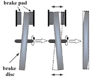
Geometric inhomogeneity of side face run-out (SFR, unit of μm) means that the side face of air-cooled brake disc has an axial lateral deviation, but without necessary changes in thickness. As shown in Fig. 2, SFR will cause slight axial displacement of the brake disc along with rotation in braking process, which will have a periodic impact on brake pads and pistons that are connected with them. It will also lead to uneven distribution of contact pressure between air-cooled brake disc and pads, change friction coefficient and equivalent radius of braking force, and cause the braking moment fluctuation and the braking pressure fluctuation [10].
Fig. 1The DTV model in brake process
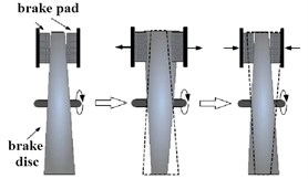
Fig. 2The SFR model in brake process
2.2. Geometric inhomogeneity model of DTV
DTV is numerically equal to the maximum thickness of the brake disc minus the minimum thickness . Assuming that the displacement of the left and right sides of the air-cooled brake disc is a sinusoidal function with time, the displacement amplitude is approximated to DTV/4, as shown in Fig. 3. Two independent displacement variables of contact between brake pad and brake disc during braking are defined as and , respectively. When the vehicle is moving with uniform deceleration, the expression of the displacement on both sides can be expressed as shown in Eq. (1):
where is initial angular velocity of air-cooled disc. is the acceleration of vehicle in braking process. is the phase difference of displacement between left and right sides of air-cooled disc.
Fig. 3Geometric inhomogeneity model of DTV
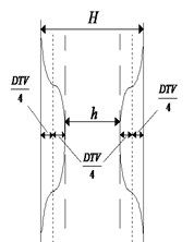
Fig. 4Geometric inhomogeneity model of SRF
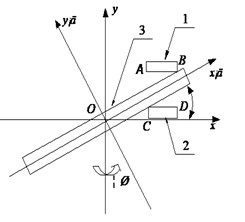
2.3. Geometric inhomogeneity model of SFR
Essentially, SRF is the axial deviation along the circumference of the end face of the air-cooled disk. As shown in Fig. 4, is defined as a fixed coordinate system. is a local coordinate system fixed on the brake disc and rotated around the axis along with the center of the brake disc. The three-dimensional space transformation relation of the two coordinate systems ( to ) is as follows:
where is installation deflection angle of air-cooled disc.
Defined the radius of air-cooled disc as , it can be known that , then the displacement of direction at the four points of A, B, C and D can be calculated as follows:
where is the internal radius of brake pad. is outer radius of brake pad.
If the phase difference between the left and right sides of the brake disc caused by the thickness difference is zero, the thickness expression of the brake disc at the contact position can be calculated as follows:
where is thickness of air-cooled brake disc at contact position of brake pad and is average thickness of air-cooled brake disc.
3. Establishment and solution of dynamic model of braking system
3.1. Geometric inhomogeneity of thickness
The air-cooled disc brake adopts sliding caliper disc structure, as shown in Fig. 5. Only the inner side of the brake disc has a cylinder, so its axial dimension is small. Because there is no oil passage across the brake disc, the brake fluid is injected from the inside, and the cooling condition of the brake wheel cylinder is good, and also the brake fluid is not easy to be heated and vaporized [11]. When the brake is working, the pressure oil reaches the cylinder through the oil inlet, and the piston and brake pad are pressed to move towards the end face of the brake disc. At this time, the brake caliper body moves left along the pin under the action of the hydraulic reaction of the inner wheel cylinder, which causes the brake pad on the outer side of the brake disc to contact with the brake disc. Finally, the braking pressure is applied to complete the braking process.
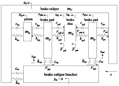
The frequency of cold vibration is lower than 100 Hz, and the cause of vibration is independent of the natural frequencies of the brake components [12]. Therefore, according to the working principle of air-cooled disc brake, the braking system can be simplified to a multi-degree-of-freedom discrete system, as shown in Fig. 6. The contact mechanics model of disc brake is established by methods of multi-body dynamics to determine the contact points of left and right pads. Displacement is set as input in this system, braking moment, braking pressure and vibration acceleration of brake clamp are set as output.
Fig. 5Structure composition and working principle
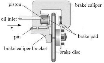
Fig. 6Dynamic model of disc brake
According to Lagrange equation, the relationship between generalized force and generalized coordinate is obtained as follows:
where is the Lagrange function, equal to the kinetic energy of the system minus the elastic potential energy . is the system damping energy.
The expression of total kinetic energy of disc brake system is:
The expression of total elastic potential energy of disc brake system is:
where is stiffness coefficient between brake caliper and cylinder piston. is stiffness coefficient between cylinder piston surface and left brake disc. is stiffness coefficient between contact surface of brake disc and pad. is stiffness coefficient between the brake caliper and the right brake pad. is stiffness coefficient between brake caliper and bracket. is stiffness coefficient between brake pad and brake caliper.
The system damping energy can be expressed as follows:
where is damping coefficient between brake caliper and cylinder piston. is damping coefficient between cylinder piston surface and left brake disc. is damping coefficient between contact surface of brake disc and pad. is damping coefficient between the brake caliper and the right brake pad. is damping coefficient between brake caliper and bracket. is damping coefficient between brake pad and brake caliper:
where is the friction force between left brake pad and brake caliper bracket in relative motion. is the friction between right brake pad and brake caliper bracket in relative motion. is the friction force produced by relative motion between left brake pad and cylinder piston surface. is the friction force between right brake pad and brake caliper. and are respectively the friction force between left and right surface of brake disc.
According to the bearing condition of brake system, the internal force system can be calculated as follows:
where , , and are coefficients of contact friction force at different locations.
The relationship between the two solutions can be expressed by matrix traveling as follows:
where is mass matrix. and is damping matrix. and is stiffness matrix.
In Eq. (24), , , , , and can be expressed as:
The matrix is defined as:
The differential equation of matrix is:
In Eq. (32):
where is 6×6 null matrix. is 6×6 unit matrix. is 6×2 null matrix.
Assuming that the brake disc rotates counter-clockwise, the force analysis on the brake disc shows that the friction force on the brake disc is the sum of the friction force on the left and right pads, which is shown as follows:
In the braking process, if the brake friction coefficient and the braking pressure of the wheel cylinder remain unchanged, the braking moment can be regarded as a constant value. But in practice, the braking process is often accompanied by jitter. That is to say, there is a certain amount of vibration in the braking moment. Therefore, the braking moment can be expressed as:
where is effective braking torque. is static torque. is dynamic torque. is effective braking radius.
According to the principle of cold vibration, it can be known that the brake torque fluctuation equals the dynamic torque :
The parameters of the braking system can be obtained from the experimental measurements as shown in Table 1.
Table 1Main parameters of dynamic model
Parameter | Value | Parameter | Value | Parameter | Value |
1.5 kg | 3.3×10⁶ N/m | 6.0 N·s/m | |||
0.12 kg | 4×10⁵ N/m | 4.0 N·s/m | |||
0.45kg | 2×10⁵ N/m | 0.09 | |||
0.15 m | 0.2 N·s/m | 0.4 | |||
7.8×10⁶ N/m | 0.3 N·s/m | 0.08 | |||
3.5×10⁶ N/m | 22 N·s/m | 0.05 | |||
6.5×10⁶ N/m | 0.2 N·s/m |
3.2. Solution of dynamic model
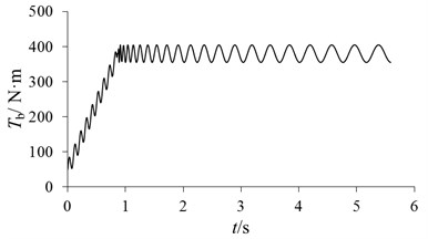
According to the dynamic differential equation of the braking system mentioned above, the fluctuation of braking moment of caused by DTV and SFR in braking process can be obtained in Fig. 7, and the effective braking torque of is shown in Fig. 8. In all graphs, parameter represents time. When air-cooled disc brake works, the vehicle speed decreases, so the variation of braking moment fluctuation will be similar to the sinusoidal curve with periodic increasing, but the magnitude of positive and negative is different, which is similar to the characteristics of input on both sides of the brake disc.
Fig. 7The braking moment fluctuation of Vt
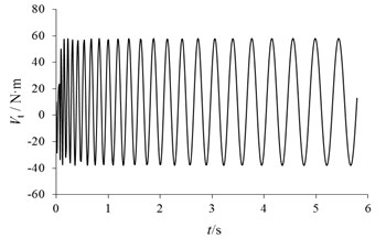
Fig. 8The effective braking torque of Tb
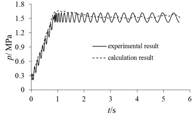
In order to verify the feasibility and reliability of the dynamic model, the bench test was adopted. The experimental research is realized based on Link3900 NVH test platform in the paper. The overall installation diagram of the disc brake and sensor is shown in Fig. 9. The brake is mounted on the spindle and synchronously rotates along with the output shaft of the reducer. According to the test results of pressure sensor, the accuracy of brake pressure calculation is validated as shown in Fig. 10. It can be seen that the brake pressure curve shows a consistent trend of change. Due to sampling frequencies [13, 14], there are some differences in vibration periods. Generally, the model has high reliability and can be used to analyze the influence of different factors.
The fluctuation of braking moment is used to measure the characteristics of cold vibration. The factors affecting the braking moment fluctuation include not only the displacement input on both sides of the air-cooled brake disc, but also the material parameters of the friction pair. Therefore, these two kinds of influencing factors are discussed respectively.
Fig. 9The overall installation diagram
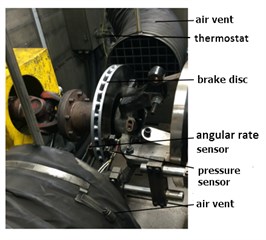
Fig. 10Verification of brake press calculation
3.3. Analysis of cold mechanical vibration
3.3.1. Effect of DTV and SFR
If we keep other parameters unchanged, the braking moment fluctuation is respectively calculated under the conditions of DTV = 10 μm, 20 μm and 40 μm, as shown in Fig. 11. It can be seen that the period of braking moment fluctuation does not change with the change of DTV, and the amplitude of braking moment fluctuation increases with the increase of DTV. Similarly, if we keep other parameters unchanged, the braking moment fluctuation can be respectively calculated under the conditions of SFR = 25 μm, 35 μm and 45 μm, as shown in Fig. 12. The effect of SFR on braking moment fluctuation is similar to that of DTV. The amplitude of braking moment fluctuation increases with the increase of SFR. However, due to the deflection of the brake disc, the difference between peak and trough is greater.
The wave peak value and trough value of with different DTV and SFR is shown in Table 2. It can be known that the linear variation of peak value for SFR is more obvious. In order to reduce the cold vibration factor, the precision of processing and installing [15] should be improved, which can especially reduce the initial value of disk thickness variation and side face run-out.
Fig. 11Changes of Vt caused by DTV
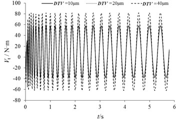
Fig. 12Changes of Vt caused by SFR
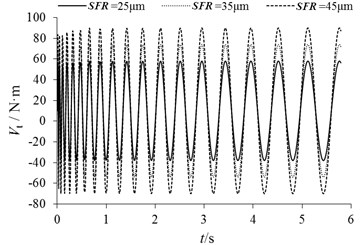
Table 2Wave peak value and trough value of Vt with different DTV and SFR
DTV / μm | Peak value of / N·m | Trough value of / N·m | SFR / μm | Peak value of / N·m | Trough value of / N·m |
10 | 59.78 | –39.94 | 25 | 57.98 | -39.94 |
20 | 70.82 | –51.36 | 35 | 73.87 | -53.63 |
40 | 82.75 | –62.24 | 45 | 89.95 | -69.87 |
3.3.2. Effect of friction pair parameters
The main parameters of friction pair include friction coefficient, stiffness coefficient and damping coefficient. The fluctuation of braking moment can be considered from the aspect of system stability [16]. According to Lyapunov’s first method, the state of non-linear system can be considered. If the maximum real part of the eigenvalue is equal to zero, the system is critically stable. However, as long as there is an eigenvalue whose real part is greater than zero, the system will lose its stability and its natural response will diverge [17]. Also, the imaginary part corresponding to the eigenvalue is the natural angular frequency of the unstable mode [18].
The maximum real part eigenvalue in this dynamic model is calculated as in Fig. 13. It can be known that the system is stable with the change of three parameters, including stiffness coefficient , damping coefficient and friction coefficient . The stability hardly varies with the change of contact stiffness and friction coefficient . But in a certain range, with the increase of the damping coefficient , the maximum real part value gradually decreases and the stability is better.
Fig. 13The maximum real part eigenvalue
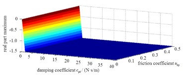
a) Condition of different and
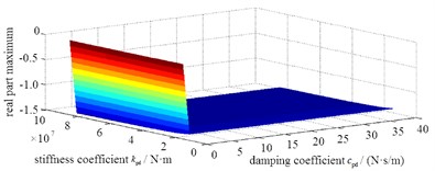
b) Condition of different and
According to the single variable method, the braking moment fluctuation under different condition of stiffness coefficient , damping coefficient and friction coefficient can be obtained as shown in Fig. 14, and the peak value and trough value is shown in Table 3. It can be seen that the amplitude of braking moment fluctuation increases with the increase of contact stiffness coefficient. With the increase of friction coefficient, the amplitude of braking moment fluctuation also increases. But, the fluctuation of braking moment does not change with the change of damping coefficient between discs and pads. That is to say, the magnitude of damping coefficient has no effect on the amplitude of braking moment fluctuation.
Fig. 14Changes of Vt with different variable
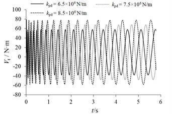
a) Changes of caused by
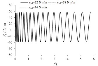
b) Changes of caused by
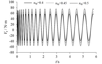
c) Changes of caused by
Table 3Wave peak value and trough value of Vt with different variable
Single variable | Peak value of /N·m | Trough value of /N·m | |
/ ×106 N/m | 6.5 | 59.65 | –40.38 |
7.5 | 67.74 | –47.95 | |
8.5 | 77.58 | –57.26 | |
/ (N·s/m) | 22 | 59.65 | –40.38 |
28 | 59.36 | –40.05 | |
34 | 58.98 | –39.59 | |
0.40 | 59.65 | –40.38 | |
0.45 | 66.05 | –45.98 | |
0.50 | 76.13 | –55.89 | |
It can be concluded that if the contact stiffness coefficient between brake disc and brake pad is reduced through material optimization [19], the amplitude of brake moment fluctuation can be effectively reduced. At the same time, on the premise of sufficient friction between disc and pads, proper reduction of friction coefficient is also one of the effective methods to reduce the amplitude of braking moment fluctuation.
4. Conclusions
The research results show that the discrete multi-degree-of-freedom vibration system is suitable for the calculation of brake cold vibration, which has important guiding significance for the research and control of noise. In addition, the air-cooled brake disc has hollow groove structure, which will amplify the cold vibration effect and would cause severe local wear and noise. Through this study, the following conclusions can be drawn.
1) The influence of different parameters on cold vibration can be evaluated effectively by using single variable method to research the braking moment fluctuation. This conclusion can provide an important basis for noise reduction and vibration reduction of disc brake.
2) The results show that the stiffness coefficient and friction coefficient have little effect on the Lyapunov stability of the brake system, and the stability of the brake system increases with the increase of damping coefficient.
3) According to the limit range of cold vibration, the amplitude of braking moment fluctuation and braking pressure fluctuation is proportional to stiffness coefficient and friction coefficient, but the damping coefficient has little effect on cold vibration.
References
-
Cam J. B., Huneau B., Verron E. Fatigue damage in carbon black filled natural rubber under uni and multiaxial loading conditions. International Journal of Fatigue, Vol. 52, 2013, p. 82-94.
-
Chu Z. G., Fangbiao Y. E., Zhang C. F. Modal correlation analysis for brake disc of rotationally periodic structures. Journal of Vibration and Shock, Vol. 32, 2013, p. 145-124.
-
Lee H., Yoon H. S. Acoustic radiation from modal vibration of automotive brake drum. Journal of Mechanical Science and Technology, Vol. 31, 2017, p. 3211-3218.
-
Li F. Z., Tong S. G. The vibration and modal analysis of the disc brake. Advanced Materials Research, Vol. 774, Issue 776, 2013, p. 78-81.
-
Tao Y. Y., Su Z. Y., Lu S. B. A study on brake noise using the complex modal analysis method. Applied Mechanics and Materials, Vols. 494-495, 2014, p. 42-46.
-
Diao K., Zhang L., Meng D. Improvement of prediction accuracy of brake squeal with complex modal FE model. Automotive Engineering, Vol. 35, 2013, p. 908-914.
-
Oberst S., Lai J. C. Statistical analysis of brake squeal noise. Journal of Sound and Vibration, Vol. 330, 2011, p. 2978-2994.
-
Zhang K., Jian C. P. The combine friction material influence on the noise of the vehicle braking. Applied Mechanics and Materials, Vol. 97, Issue 98, 2011, p. 756-760.
-
Lindberg E., Hörlin N. E., Göransson P. An experimental study of interior vehicle roughness noise from disc brake systems. Applied Acoustics, Vol. 74, 2013, p. 396-406.
-
Kecskeméthy A., Weinberg A. An improved elasto-kinematic model of the human forearm for biofidelic medical diagnosis. Multibody System Dynamics, Vol. 14, 2005, p. 1-21.
-
Taylor W. R., Roland E., Ploeg H. Determination of orthotropic bone elastic constants using FEA and modal analysis. Journal of Biomechanics, Vol. 35, 2002, p. 767-773.
-
Wang J. Modeling and modal analysis of tool holder-spindle assembly on CNC milling machine using FEA. Applied Mechanics and Materials, Vol. 157, Issue 158, 2012, p. 220-226.
-
Wagner U., Schlagner S. On the Origin of Disk Brake Squeal. International Journal of Vehicle Design, Vol. 51, 2009, p. 223-237.
-
Konarski S. G., Hamilton M. F., Haberman M. R. Vibration damping materials with enhanced loss due to microstructural nonlinearity. Acoustical Society of America Journal, Vol. 141, 2017, p. 3642-3642.
-
Takezawa A., Daifuku M., Nakano Y. Topology optimization of damping material for reducing resonance response based on complex dynamic compliance. Journal of Sound and Vibration, Vol. 365, 2016, p. 230-243.
-
Fajri P., Lee S., Prabhala V. A. Modeling and integration of electric vehicle regenerative and friction braking for motor/dynamometer test bench emulation. IEEE Transactions on Vehicular Technology, Vol. 64, 2016, p. 4264-4273.
-
Zhou K., Chen L., Pan C. Electric vehicle regenerative braking system based on constant current control of composite power sources. Journal of Mechanical Engineering, Vol. 49, 2013, p. 78.
-
Zh Jin L., Sh Guo L., Shi R. K. Dynamic performance analysis and experimental study of automotive electronically controlled hydraulic braking system. Journal of Mechanical Engineering, Vol. 48, 2012, p. 127-132.
-
Zhu Zh G., Zhou Y. M., Jiang Zh H. Design of an on-line detection system for natural frequencies of brake discs. Mechanical Science and Technology, Vol. 31, 2012, p. 723-725.
-
Lu M. H., Zhang L. J., Yu Zh P. Research progress on screaming of disc brakes in automobiles. Vibration and Shock, Vol. 30, 2011, p. 1-7.
-
Yin X. D., Zhang L. J., Ning G. B. Bench test of braking moment fluctuation. Vibration, Test and Diagnosis, Vol. 25, 2005, p. 12-15.
-
Xiao J. B., Yang G. L., Hong L. I. Influences of matching muzzle brake and buffer on weapon recoil. Journal of Ballistics, Vol. 29, 2017, p. 86-92.
-
Duan H. J., Tao H. Random vibration isolation and parameter optimization on two-stage vibration isolation system in vehicle. Noise and Vibration Control, Vol. 3, 2007, p. 79-82.
-
Hoseinnezhad R. Position sensing in brake-by-wire callipers using resolvers. IEEE Transactions on Vehicular Technology, Vol. 55, 2006, p. 924-932.
-
Delfani M. R. Extended theory of elastica for free torsional, longitudinal, and radial breathing vibrations of single-walled carbon nanotubes. Journal of Sound and Vibration, Vol. 403, 2017, p. 104-128.
-
Wang C. X., Mo J. L., Yang Zh J. Test and finite element analysis of texture surface affecting scream noise of brake disc materials. Vibration and Shock, Vol. 24, 2015, p. 182-187.
-
Peng D. H. Regression explanation of one-way ANOVA. Journal of Qingyuan Vocational and Technical College, Vol. 3, 2014, p. 110-112.
About this article

The paper is supported by Doctoral Research Fund (2017Y22), National Natural Science Foundation of China (51705028) and Shandong Natural Science Foundation (ZR2016EEB36).
