Abstract
The article considers new dynamic effects arising in problems of vibration protection of objects under external disturbances, on the side of support surfaces. A method for constructing mathematical models for a vibration protection system is developed, in which the protection object has two degrees of freedom. It is demonstrated that is possible to introduce additional constraints in the form of motion transformation devices. The article estimates the possibilities of using screw non-locking mechanisms with flywheel nuts, the given moment of inertia of which can be regulated.
1. Introduction
In the problems of the dynamics of technological machines and vehicles, much attention is paid to the issues of vibrational interactions of elements of mechanical oscillation systems (MOS) [1-4]. Effects of dynamic damping of oscillations are widely used in various branches of technology [5-8], which is associated with the study of the features of the dynamic properties of objects [9-11], most often selected as a mass-and-inertia element, whose dynamic state is estimated by one coordinate.
In works concerned with controllable systems as part of the MOS, servo drives, elements of pneumatic, hydro-, and electrical automation are used [12-14]. Although the problems of analysis and dynamic synthesis of the MOS have been in progress, the methods of structural mathematical modeling have been developed to a lesser extent, oriented toward using the analytical tools of the automatic control theory, which provides great possibilities for estimating the dynamic states of objects having several degrees of freedom [2, 3, 9, 15]. The main provisions of structural mathematical modeling are given in [8, 13, 16-18].
The proposed article develops a methodological basis for constructing mathematical models for vibration protection systems with an object of protection in the form of a solid body that performs a plane motion under the influence of a kinematic perturbation, taking into account that it’s possible to implement dynamic damping modes simultaneously in two coordinates.
2. Some general provisions. Statement of the research task
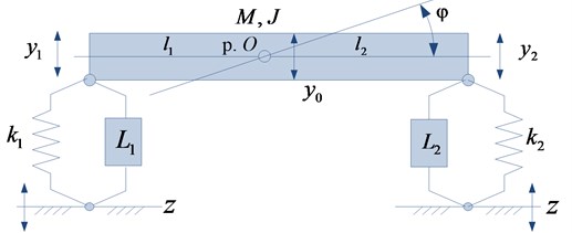
We consider a vibration protection platform for the installation of instrumentation, which is subject to vibrations on the side of the supporting surface (Fig. 1). The object in the form of a solid body with mass and moment of inertia is supported by elastic elements with stiffnesses and with parallel-mounted motion transformation devices (MTD) having reduced masses and , respectively [11, 17].
The system under consideration has linear properties and performs small oscillations with respect to the static equilibrium position. The position of the center of gravity (p. O) is determined by the lengths of the arms and . The and coordinate system associated with the fixed base is used. The frictional forces in the system are not taken into account, the external action is a harmonic function.
Fig. 1Schematic diagram of the vibration protection platform in the form of a rigid body with elastic-inertial supports with kinematic perturbation zt
To obtain a mathematical model, using the Lagrange equations of the second kind, an expression is determined for the kinetic and potential energies:
To carry out the appropriate calculations, we take into account the following relations:
Using the Eq. (1)-(3), on the basis of known methods we obtain a mathematical model in the form of a system of two linear inhomogeneous differential equations with constant coefficients. After the Laplace transform under zero initial conditions, these equations in the operator form become:
where is the complex variable (); icon “–” corresponds to the Laplace transform of the variable.
On the basis of Eqs. (4), (5) a structural mathematical model can be constructed, as shown in Fig. 2; the system has an external perturbation simultaneously at the inputs of two partial systems.
Fig. 2Structural mathematical model of the system by Fig. 1 in the form of a block diagram of an equivalent (dynamically) automatic control system
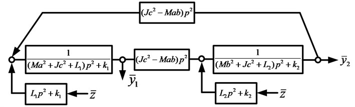
Using the block diagram in Fig. 2, we write the transfer functions of the system:
where:
is the characteristic frequency equation.
We note that and can take zero values if condition:
At a frequency determined by the relation , it is possible to simultaneously “nullify” the coordinates and , which can be considered as a mode of dynamic damping of the oscillations of the protection object simultaneously in the two coordinates and under the kinematic perturbation from the support surface side.
The task of the research is to study the possibilities of forming modes of dynamic damping of the object’s oscillations simultaneously in two coordinates, using data on the available forms of a purposeful change in the ratio of the parameters of the systems for configuring the parameters of the dynamic state of the object.
3. Construction of mathematical models of interactions
Using relations Eq. (9), assuming that , we write the transfer functions Eqs. (6), (7) in the form:
where:
We note that in the construction of transfer functions of the system, simultaneous transmission of influences to both inputs of the system is taken into account, while is regarded as an adjustable connectivity coefficient of the parameters of the reduced masses of the MTD.
The partial frequencies of the system are determined by the expressions, respectively:
Note that the partial frequency does not depend on α.
In the MOS under consideration (Fig. 1), it is possible to create dynamic oscillation damping modes in two coordinates, which is determined by the possibility of “nullifying” the numerators of the transfer functions Eqs. (10), (11).
For the coordinate , we can write the following equation for finding the frequencies of the dynamic damping of oscillations under the kinematic perturbation :
Eq. (15) can be reduced to the form of a biquadratic equation, assuming that , then Eq. (15) takes the form:
where:
The solution of Eq. (15) can have, with a certain set of parameters of the system, two real positive roots:
In turn, from the coordinate we obtain that:
where:
The introduction of the connectivity coefficient α between the parameters and changes the transfer functions Eqs. (6), (7), and hence the values of the frequency of the dynamic damping of the oscillations determined by Eqs. (16) and (19). In this case, the characteristic frequency equation also changes, that is, the frequencies of proper oscillations also change accordingly.
Taking into account the connectivity coefficient , we shall use, using Eqs. (15) and (18), an equation for determining the frequencies of dynamic damping, , .
The frequencies of the natural oscillations , can be found from the solution of the characteristic Eq. (12), which can be represented in the form of:
We note that the frequencies of the natural oscillations in this case will depend on the connectivity coefficient .
4. Discussion of the results
Under the kinematic perturbation of the initial system (Fig. 1), as shown in the structural scheme shown in Fig. 2, an external disturbance is distributed simultaneously over two inputs. The use of the principle of superposition results in a change in the form of transfer functions in comparison with conventional approaches, when only one input is perturbed.
Under the action of one external perturbation in a system with two degrees of freedom, the numerator of the transfer function along the coordinate of the application of force. It is formed on the basis of the parameters of the corresponding partial system. According to another coordinate, the numerator of the transfer function is created due to the parameters of the link that implements interpartial bonds, which, on the whole, depends on the choice of the coordinate system. In the standard situation, the MOS in Fig. 1 in the coordinates , for a force perturbation with respect to the coordinate will have one mode of dynamic damping of the oscillations, at a frequency determined by the expression:
In the second coordinate with force perturbation, the dynamic damping mode is not assumed, but due to the specificity of the transfer function of the link of the interpartial bond with the transfer function:
the coordinate can acquire zero values when the condition is fulfilled.
Using formulas for determining the frequencies of partial and natural oscillations, as well as the frequencies of dynamic damping of oscillations, it is possible to construct a frequency diagram that reflects the features of the dynamic interactions of the initial MOS, as shown in Fig. 3.
To specify the representations, a model problem with parameters 10 kg was solved; 5 kg.m2; 0.4 m; 0.6 m; 1; 5000 N/m; 10,000 N/m; 10 kg; .
Fig. 3Diagram of dynamic interaction modes ((L1, L2=αL1): the notation of the dependencies ω1din2(α), ω2din2(α), ω1sob2(α), ω2sob2(α), n12(α) and n22(α) are given directly in the text
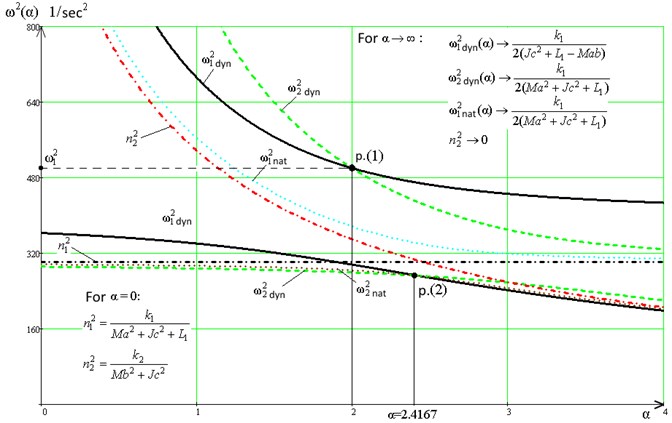
In the diagram (Fig. 3) the solid line (––) indicates the dependency graphs, the numerator of the transfer function Eq. (10) is used to construct the graph. The value of the frequencies depends on the connectivity coefficient . Since the frequency of the dynamic damping of the oscillations along the coordinate is determined from the biquadratic frequency equation, the graph is represented in the diagram (Fig. 3) by two fragments (or branches): the lower branch of the graph corresponds to low-frequency forms of motion. In turn, the plot of the frequency of the dynamic damping of the oscillations along the coordinate is determined from the frequency equation formed by the numerator of the transfer function Eq. (11). In the diagram (Fig. 3), both branches of the graph are indicated by a dashed line (- - -).
In the case under consideration, the partial frequencies of the system determined by Eqs. (13), (14) are also represented in Fig. 3 by graphs , and are denoted by dash-dotted lines (∙-∙-). The graph of the dependence is a straight line parallel to the abscissa axis, since , as it follows from Eq. (13), and does not depend on . The graphs of the dependences and can be constructed based on the use of the frequency characteristic Eq. (12). In Fig. 3 graphs and are denoted by dotted lines (∙∙∙∙).
5. Conclusions
Technically, such capabilities can be implemented with the help of special mechanisms controlled on the basis of measuring the current parameters of the dynamic state of the object of vibration protection. The authors suggest a method for constructing mathematical models of the system, based on the use of transfer functions of the system. The proposed analytical tools rely on the method of structural modeling, in which the mechanical oscillatory system is compared with a dynamically equivalent structural diagram of the automatic control system.
References
-
Chelomei V. N. Vibrations in Technology: a Handbook in 6 Volumes. Protection from Vibration and Shocks, Vol. 6, Mashinostroenie Publishers, Moscow, 1981, p. 456, (in Russian).
-
Harris S. M., Piersol A. G. Shock and Vibration Handbook. McGraw-Hill Book Co, New York, 2002, p. 1457
-
De Silva C. W. Vibration. Fundamentals and Practice. CRC Press, Boca Raton, London, New York, Washington, 2000, p. 957, (in Russian).
-
Belokobylsky S. V., Eliseev S. V., Kashuba V. B. Applied Problems of the Structural Theory of Vibration Protection Systems. Polytekhnika, St. Petersburg, 2013, p. 363, (in Russian).
-
Eliseev S. V., Nerubenko G. P. Dynamic Vibration Dampers. Nauka Publishers, Novosibirsk, 1982, p. 144, (in Russian).
-
Korenev B. G., Reznikov L. M. Dynamic Vibration Dampers: Theory and Technical Applications. Nauka Publishers, Moscow, 1988, p. 304, (in Russian).
-
Karamyshkin V. V. Dynamic Damping of Oscillations. Mashinostroenie, Leningrad, 1988, p. 108, (in Russian).
-
Eliseev S. V., Khomenko A. P. Dynamic Damping of Vibrations: the Concept of Feedback and Structural Methods of Mathematical Modeling. Nauka Publishers, Novosibirsk, 2014, p. 357, (in Russian).
-
Kolovsky M. Z. Automatic Control of Vibration Protection Systems. Nauka Publishers, Moscow, 1976, p. 320, (in Russian).
-
Eliseev S. V. Structural Theory of Vibration Protection System. Nauka Publishers, Novosibirsk, 1978, p. 221, (in Russian).
-
Eliseev S. V., Lukyanov A. V., Reznik Yu N., Khomenko A. P. Dynamics of Mechanical Systems with Additional Ties. Irkutsk State University, Irkutsk, 2006, p. 315, (in Russian).
-
Eliseev S. V., Kuznetsov N. K., Lukyanov A. V. Controlling the Vibrations of Robots. Nauka Publishers, Novosibirsk, 1990, p. 320, (in Russian).
-
Eliseev Reznik Yu S. V. N., Khomenko A. P. Mechatronic Approaches to the Dynamics of Mechanical Oscillation Systems. Nauka Publishers, Novosibirsk, 2011, p. 384, (in Russian).
-
Kuznetsov N. K. Dynamics of Controlled Machines with Additional Constraints. IrGTU, Irkutsk, 2009, p. 290, (in Russian).
-
Chernousko F. L., Akulenko L. D., Sokolov B. N. Control of Oscillations. Nauka Publishers, Moscow, 1980, p. 384, (in Russian).
-
Khomenko A. P., Eliseev S. V., Ermoshenko Yu V. System Analysis and Mathematical Modeling in the Mechatronics of Vibration Protection Systems. ISTU, Irkutsk, 2012, p. 288, (in Russian).
-
Eliseev S. V., Artyunin A. I. Applied Theory of Oscillations in Problems of the Dynamics of Linear Mechanical Systems. Nauka Publishers, Novosibirsk, 2016, p. 459, (in Russian).
-
Karnovsky I. A., Lebed E. Theory of Vibration Protection. Springer, Switzerland, 2016, p. 708.
About this article

