Abstract
The movement time of the projectile is the basic parameter for studying the gesture of the projectile. It is also the time base for the test of projectile shots. At the same time it is the time base for the test of gun vibration response. A test method for the moving time in the bore of a projectile which is based on the barrel strain test is proposed in this paper. First, paste a plurality of strain gauges along the axis of the barrel. Then take the rising edge time of the strain-time curve of each measuring point as the movement time of the Projectile. The artillery fired and the projectile moved at high speed inside. By testing the external surface strain time curve, and then through data processing, the time of a large-caliber artillery projectile in orbit was obtained. Through the firing test in the shooting range, the validity and correctness of the method are verified.
1. Introduction
Artillery is an important weapon in the war and has always been the focus of the development of the world’s military power. When the artillery is fired, the projectile moves at a high speed along the axis of the body tube under the action of rolling. The projectile and the artillery are coupled to each other, causing initial disturbance of the projectile. After the projectile flies through the outer ballistic flight, the phenomenon of projectile scattering occurs. The movement posture and movement time of the projectile have an important influence on the firing accuracy of the artillery. If the movement posture of the projectile is large and the frequency is high, the firing accuracy of the artillery will be low. The movement time of the projectile is the basic parameter for studying the gesture of the projectile. It is also the time base for the test of projectile shots. At the same time it is the time base for the test of gun vibration response. Only when the movement time in the projectile is obtained can the accurate posture of different positions in the projectile be known. The artillery launch has the characteristics of high speed, high pressure and strong impact. When the projectile left the muzzle, the muzzle vibrated violently. When processing vibration curve data, tiny time error will cause the calculated muzzle vibration response size to be greatly different. Therefore, the research of the time measurement technology for the movement time of projectiles in the bore has always been one of the most important issues in the research field of artillery structure vibration technology.
The literature [1] uses the electric bottom fire firing method to start the projectile in the crucible, and the projectile start time is obtained. In the literature [2], the p-t curve of the ignition process of the propellant is recorded by a pressure sensor. The ignition time when the pressure rises to the specified pressure is determined by the p-t curve. In the literature [3], four methods, such as high-speed photography, target wire breaking method, photoelectric method and recoil displacement method, are used to study the time parameter test method of the projectile muzzle moment. Literature [4] proposed a test method for the time and distance of the projectile after the effective period. Reference [5] defines projectile zero point, that is, the time when the projectile flies away from the muzzle. It is the key data in the performance analysis and test of the artillery. In the literature [6], the echo signal characteristics of high-velocity artillery projectiles are analyzed, and a projectile echo analysis method based on short-time Fourier transform is proposed. A common feature of the above documents is that although these documents all involve time testing methods, none of them involve the motion time in the chamber of a projectile [7].
In order to provide the results of the time-variation of the position of the projectiles, a method based on the strain test of the body is proposed, and the time test principle is given. The effectiveness and correctness of the method are verified by the shooting test of the shooting range.
2. Principle of the test
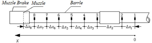
The movement time of the projectile and the position of the movement of the projectile, as well as the relationship between the two, are given by the strain curve of the tube. The position and time of the motion of the projectile are obtained by using the tube strain test principle. Select 8 strain measurement points as an example to illustrate the test principle, as shown in Fig. 1. The first measuring point is the origin of the axial coordinate, and the eighth measuring point is close to the muzzle. All measuring points are arranged along the axis of the tube, and each measuring point is pasted with a one-way resistance strain gauge. The direction of deformations sensitivity of strain gauge is along the circumference of barrel. Strain gages are used to obtain deformations of the body measurement points in the circumferential direction during the movement of the projectiles. The deformation variation of the strain gauge is converted into the resistance change amount, and the strain time curve is obtained by the data collector in real time. During the movement of the projectile, the inside of the bore is divided into two parts by the band: after the band (near the bottom of the bore) and before the elastic band (near the muzzle). Because there is no pressure before the band, the strain in the circumferential direction of the tube in this position is very small. However, there is a back pressure after the band, so the strain in the circumferential direction of the barrel is large at this position. The rapid rise of the strain curve in the circumferential direction of the barrel corresponds to the position of the elastic band. In this way, by recording the time at which the strain curve rises and combining the position coordinates of each measurement point, the correspondence between the movement position and time of the projectile in the bore can be obtained. The artillery body tube is divided into a guide section and an outreach section. The guide section moves within the cradle and the outreach section does not contact the cradle. During the firing process, the outreach section extends in front of the cradle. The method in this paper only involves the test of the movement time of the projectile in outreach section.
Fig. 1Layout of strain-time measurement point
One of the keys to accurately obtaining the correspondence between the position and time of the projectile is how to accurately obtain the time when the projectile leaves the muzzle. Therefore, this purpose is achieved using a high speed digital camera, data collector and time synchronization controller. The specific method is that before the artillery is fired, a high-speed digital camera is arranged on the side of the muzzle, and the data collector and the time synchronization controller are arranged on the test vehicle, and the time synchronization controller is used to time synchronize the high-speed digital camera and the data collector. The artillery fired, the process of the projectile leaving the muzzle was captured by a high-speed digital camera, and the high-speed digital camera trigger signal and the strain time signal of barrel were acquired by the digital collector. The time when the projectile leaves the muzzle can be obtained by analyzing the data collector test curve information.
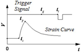
Fig. 2 shows the relationship between the time characteristic point of the strain curve of the barrel and the time when the projectile leaves the muzzle. Where, indicates the trigger moment of the high speed digital camera; a indicates the time when the projectile is out of the muzzle, which is calculated by the high-speed digital camera method; indicates the start time of the barrel strain time curve rise; represents the time at the peak of the strain barrel time curve; represents the voltage value corresponding to the body barrel strain time signal and the time trigger signal; represents time.
Fig. 2The relationship between the time characteristic point of the strain curve of the barrel and the time when the projectile leaves the muzzle
The shot time of the projectile is obtained according to the following procedure.
First, two time coordinate systems are established, one is the high-speed digital camera time coordinate system, and the time origin is the post-trigger time, as shown in Fig. 2. The other is the data collector time coordinate system, the time origin is the data collector trigger time, as shown in Fig. 2, the 0 axis of the abscissa axis. High-speed digital camera uses a post-trigger method. Then, the high-speed digital camera trigger time signal and the barrel strain time curve are collected and recorded by the same data collector. In this way, the time information contained in the barrel time curve is correlated with the time series of high speed digital camera image. Then, by playing back the sequence of images captured by the high-speed digital camera, the time () when the projectile exits the muzzle relative to the time of the trigger in coordinate system of high speed digital camera is obtained. Then the time when the projectile exits the muzzle in the data collector time coordinate system is:
It should be noted that is a negative value because it is a post-trigger mode. , , , , are all in the data collector time coordinate system.
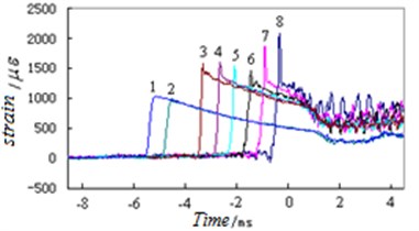
Fig. 3The test result of the typical strain time curve
3. Verification of the principle
A large-caliber gun barrel was used as the verification object, and one shot was fired. The correctness of the principle is verified by analyzing the strain test curve of the barrel. Fig. 3 is the test result of the typical strain time curve of eight strain points on the barrel of the same shot during the movement of the projectile. The abscissa axis 0 indicates the moment when the projectile exits the muzzle, and the negative time indicates the period during the movement of the projectile. The numbers 1, 2, … and 8 on the strain time curve indicate the first measurement point, the second measurement point, ..., and the eighth measurement point strain curve of the barrel.
3.1. Selection of the corresponding relationship between the characteristic points of the strain time curve and the position of the elastic band
There are two characteristic points in the strain measurement time curve of the barrel: the rapid rise starting point and the peak point. Is the point representing the position of the elastic band the starting point of the strain time curve of the barrel or the peak point of the strain time curve of the barrel? The correct conclusion is that the starting point of the rise of the strain time curve represents the position of the elastic band, and the reason is given by the following process.
If: represents the difference between the time when the projectile exits the muzzle and the time at which the strain time curve rises, ; represents the difference between the shot time when the projectile exits the muzzle and the peak time of the strain time curve, ; represents the average speed between the 8th measuring point and the muzzle, and the 8th measuring point is closest to the muzzle (as shown in Fig. 1); represents the distance between the 8th measuring point and the muzzle.
The formula for calculating the average time from the 8th measuring point to the muzzle of the projectile is:
According to the internal ballistics of a large-caliber artillery, the velocity of the projectile at the muzzle is m/s. At a position of 0.405 mm from the muzzle (the 8th measuring point), the projectile speed is ( 10) m/s. In this distance range, the average velocity of the projectile is (5) m/s, and the motion time of the projectile is 0.000438 s = 0.438 ms.
The results of live-fire test show that the time taken for the projectile to move from the eighth point to the muzzle is 0.438 ms. The test results are consistent with the theoretical calculation results.
Table 1Rising start time of the strain time curve can be used as the basis for determining the position of the elastic band
Variable | - | |||||
Value/s | 3.406115 | 3.405677 | 0.000438 | 0.000438 | 0.0 |
Table 2the peak time of the strain time curve cannot be used for determining the position of the elastic band
Variable | - | |||||
Value/s /s | 3.406115 | 3.405855 | 0.000266 | 0.000438 | 0.000177 |
Table 1 verifies that the rising start time of the strain time curve can be used as the basis for determining the position of the elastic band. Table 2 shows that the peak time of the strain time curve cannot be used for determining the position of the elastic band. Table 1 shows that if the strain curve rise starting point time is taken as the feature point for determining the position of the elastic band, the time thus obtained is consistent with the internal ballistic calculation result. So, we can be sure that this choice is correct. Table 2 shows that if the peak point time of the strain curve is used as the feature point for determining the elastic band position, the error between the time and the calculated result is 0.177 ms. Therefore, the peak point time of the strain curve cannot be used as a feature point for determining the position of the elastic band. In Tables 1 and 2, the time values are obtained by the data collector. The numerical origin is the trigger moment of the data collector, which is the 0 point of the abscissa axis of Fig. 2.
3.2. Test results of the relationship between the characteristic points of the strain-time curve and the position of the elastic band
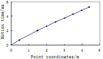
The measuring points are arranged in the manner shown in Fig. 1. The test results of the correspondence between the coordinates of the strain measurement points of the barrel under the shooting conditions and the movement time of the projectile are obtained, as shown in Table 3. Where a represents the spacing between the measuring point 1 and the measuring point 2, and the rest are analogous. The results in Table 3 show that with the measurement point 1 as the time reference and the coordinate reference, the elastic belt movement is 0.69 ms when the elastic belt moves to 0.457 m; when the elastic belt moves to 4.399 m, the elastic belt movement is 5.26 ms.
The last two columns of data in Table 3 are plotted as curves, and the results are shown in Fig. 4. It can be seen from the shape of the curve that as the elastic belt moves from the strain measuring point 1 to the muzzle process, the slope of the curve gradually decreases and the curve is concave downward. This shows that the movement time of the elastic belt is getting shorter and shorter, which is consistent with the actual situation, indicating that the test result is correct.
Table 3Relationship between the coordinates of the strain measurement point of the barrel and the movement time of the elastic band
Measuring point | 1 | 2 | 3 | 4 | 5 | 6 | 7 | 8 | Muzzle |
Point coordinates / m | 0 | 0.457 | 1.474 | 1.999 | 2.504 | 3.011 | 3.487 | 3.994 | 4.399 |
Time / ms | 0 | 0.69 | 2.0 | 2.61 | 3.18 | 3.74 | 4.27 | 4.82 | 5.26 |
Fig. 4The relationship between the stroke of the elastic belt and the movement time
4. Measurement uncertainty analysis
The test error of the movement time in the projectile is mainly derived from: 1) Strain response time; 2) Measuring point distance measurement.
The error caused by first factor is 0.001 ms, which is a uniform distribution. The relative standard uncertainty introduced by this factor is:
The distance error caused by second factor is 0.1 mm, and the equivalent time error is 0.000111 ms, which is a uniform distribution. The relative standard uncertainty introduced by this factor is:
The relative standard measurement uncertainty of the movement time of the projectile is:
Under normal circumstances, the maximum time of motion in the projectile is 15 ms, and the standard measurement uncertainty of the motion time in the projectile is:
The confidence level is 99.7 %, the factor 3, and the uncertainty of the motion time expansion of the projectile is obtained:
In summary, the uncertainty of the movement time expansion of the projectile is 0.00087 ms, which satisfies the test error of the movement time of the projectile.
5. Conclusions
This paper proposes a method for time testing using body strain. Specifically, multiple strain gauges are attached to different measuring points along the axis of the barrel. The rising time of the strain time curve of each measuring point is taken as the movement time of the elastic belt, so as to determine the movement time of projectile in the bore. The artillery fired and the projectile moved at high speed in the raft. Through the test results of the strain time curve of the outer surface of the barrel, the movement time of a large-caliber gun projectile were obtained. The test results will provide time-based parameters for the test of projectile movement posture in bore and the vibration response of the muzzle.
References
-
Hou Jian, Wei Ping, Li Jinxin Interior ballistics modeling and simulation of conic chamber gun system. Acta Armamentarii, Vol. 31, Issue 4, 2010, p. 419-422, (in Chinese).
-
Zhao Baoming, Zhang Zouzou, Zhang Heng, et al. Experiment research for the ignition performance of gun propellant with ignition delay device. Chinese Journal of Explosives and Propellants, Vol. 39, Issue 4, 2016, p. 102-106, (in Chinese).
-
Wang Baoyuan, Chao Hongxiao, Shao Xiaojun, et al. Measurement methods for muzzle-leaving time of projectile. Acta Armamentarii, Vol. 33, Issue 6, 2012, p. 736-740, (in Chinese).
-
Wang Baoyuan, Chao Hongxiao, Shao Xiaojun, et al. The measurement method of time and distance in ulterior period for projectile. Acta Armamentarii, Vol. 34, Issue 10, 2013, p. 1329-1333, (in Chinese).
-
Hou Jianqiang, Han Zhuangzhi, Wang Ningke Status and development trend of bullet zero-time pot acquiring methods. Fire Control and Command Control, Vol. 40, Issue 7, 2015, p. 1-3, (in Chinese).
-
Shi Lin, Ju Feng, Hu Wenhua A test method based on STFT about high firing rate gun projectile at moment of projectile muzzle-leaving. Journal of Gun Launch and Control, Vol. 35, Issue 2, 2014, p. 35-39, (in Chinese).
-
Wang Baoyuan Measurement Technology of Dynamic Parameters for Projectile. The Publishing House of Ordnance Industry, Beijing, 2017, (in Chinese).
About this article

Guo Min, Shao Xiaojun, Zhang Pengfei, Du Wenbin, Li Shili, Yang Wei, and Liu Jun also participated in the experimental work of this article and paid for the experimental work of this article. We are grateful for this.
