Abstract
The measurement of shot exit time is very important to measuring data analysis of muzzle vibration. Optoelectronic method, which is based on the optical-electrical conversion theory and timed with the muzzle flame, is a general method of measuring the shot exit time for the major caliber gun. However, it has not been identified that the shot exit time corresponds to which characteristic point in the voltage pulse time signal curve obtained by the optoelectronic method. In this paper, by combining the high speed digital photography and the optoelectronic method, both the triggering time signal of the high speed digital photography and the voltage signal output by the optoelectronic sensor were obtained simultaneously. Then by comparing the voltage time curve of the optoelectronic sensor with the photographs obtained by the digital photography, the relationship between the characteristic points in the signal curve and the shot exit time was identified. It has been shown that, the voltage pulse beginning time is the same with the muzzle flame beginning, which is later than the time when the projectile band leaves from muzzle.
1. Introduction
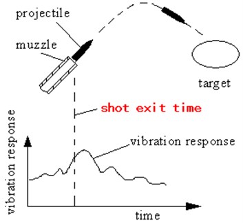
Muzzle vibration occurs when the gun is fired. The muzzle vibration response has an important influence on gun firing accuracy. Only the vibration response of the projectile at the muzzle can affect the firing accuracy. It is very important to obtain the shot exit time accurately. Measuring shot exit time is the basis of muzzle vibration analysis. Fig. 1 is the sketch of the role of the shot exit time in the vibration measurement.
When the gun is shooting, the high temperature and high pressure powder gas generated by propellant propels the projectile and make it accelerate towards the muzzle in high speed. In this article, the time that the projectile band leaves from the muzzle is defined as the shot exit time.
In the firing test of the major caliber gun, the optical-electrical conversion theory based on the optical-electrical time sensor is commonly used to measure the shot exit time. When the gun fires, timed with the muzzle flame, getting the information of muzzle flash based on the photoelectric conversion principle, and recording the voltage pulse time signal curve by data collector, is a generally method to find time of muzzle flame appears and then obtain the shot exit time. However, which point on the curve corresponds to the shot exit time the initial one or the maximum one? Or some other point? For many years, it has not been identified due to the limitation of the test condition. This problem has seriously affected the precision of the vibration data process. In practical engineering, the starting point of the voltage pulse time signal curve or the upper endpoint on the curve’s increasing segment is usually regarded as the shot exit time.
Aim at the measurement of the shot exit time, the author had ever used the floating displacement of receiver to ensure the shot exit time when they study the vibration test and dispersion test of small-caliber gun muzzle [1]. And it provides a time reference for the gun’s vibration curve. However, it cannot be used to analyze major-caliber gun since the range of sensor is too small. Zhang Zhiquan et al. [2] regarded the electric pulse fired by gun as the reference time of the gun’s angular displacement response, but it will cause great errors in calculating the shot exit time. Lu Dongqu et al. [3] mentioned the shot exit time in their article but did not give a method to measure it. A study of measuring the aftereffect period and distance of the pill was carried out [4], but it did not mention the test to measure the shot exit time. Wang Baoyuan et al. [5] regarded small-caliber gun as experimental objects, used high speed photography and other three kinds of method to study the measurement of shot exit time. But this method does not study the relationship between muzzle flame of major-caliber gun and signal of photoelectric sensors deeply. Nowadays, in this field, high speed photography, light curtain method, sky curtain method method and acoustic method have been widely used abroad. But these methods can’t be used to analyze major-caliber gun. The muzzle pressure sensor was used to record the shot exit time [6]. But it is not introducing the mechanism of the measurement. In foreign countries, they usually fix the target on the muzzle and get the shot exit time by the coil, provide time information for the control system and settlement of projectile fuse, in order to improve the shooting accuracy. It really has good result. But, this method did not show its advantages in the conventional test of firing. And it’s clear that none of the above documents relate to a photoelectric method.
The purpose of this paper is to study the test mechanism of optoelectronic method by means of a high speed digital photography. Through research of testing mechanism and engineering verification, both the triggering time signal of the high speed digital photography and the voltage signal output by the optoelectronic sensor were obtained simultaneously. Then by comparing the voltage time curve of the optoelectronic sensor with the photographs obtained by the digital photography, the relationship between the characteristic points in the signal curve and the shot exit time was identified.
Fig. 1Sketch of the role of the shot exit time in the vibration measurement
2. Testing principle
The testing principle is showed in Fig. 2. The gun is fixed on the certain position and the scene of the optoelectronic sensor is aligned to the muzzle, using data collector to record signal of the muzzle flame in order to get the moment of flame appears. So that the shot exit time can be obtained. When the gun fires, during the projectile leaving the muzzle, there will be a bright flame around the muzzle. The optoelectronic sensor detects the muzzle flame and forms a voltage pulse signal, shown as in Fig. 3. Data collector records this signal, and then the shot exit time is obtained.
The core element of optical-electrical time sensor is silicon photocell. Silicon photocell is a kind of optoelectronic devices which can convert light energy into electrical energy directly. Thus, when the muzzle flame aligns to silicon photocells, the shot exit time can be obtained by testing the output voltage of silicon photovoltaic cells.
In order to know the shot exit time based on the feature point on the voltage pulse signal curves, a method which combines the high-speed digital photography method and photoelectric method is proposed. In details, high-speed digital imaging method is used to record the image sequence while the projectile leaves from the muzzle and photoelectric method is used to record voltage pulse signal formed by muzzle flame. As Fig. 2, the trigger signal transferred from the high-speed digital photography and the output voltage pulse signal of muzzle flame transferred from the optoelectronic sensor are inputted into a data acquisition at the same time. The high-speed digital camera is in post trigger. At the end of gun firing, the trigger signal of high-speed digital cameras is started and high-speed digital video camera stop working, as well as the image before the trigger signal is recorded.
Fig. 2Sketch map of measurement method of shot exit time
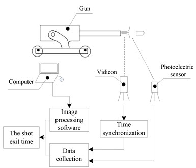
Fig. 3Sketch map of the voltage pulse time signal and the triggering time signal of high speed digital photography
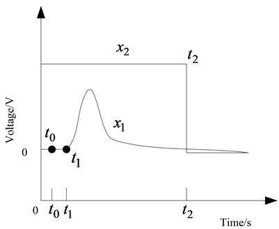
As Fig. 3, the trigger signal of high speed digital cameras and the voltage pulse signal of the muzzle flame based on the optoelectronic method are shown. These two signals are recorded by a same collector. The muzzle flame is regarded as time principle of , means the time when the band of projectile leaves the muzzle, means the time when the muzzle flame appears and also means the starting point on the rapid-increasing part of the pulse curve, and means post trigger time of the high-speed digital camera. On the horizontal axis, 0 means the start time of data collecting, while the coordinate is the trigger signal. When the trigger signal is high, the high-speed digital cameras capture a sequence of images. When low, high-speed digital camera stops recording.
Fig. 4 shows the trigger time coordinate system of the high-speed digital camera. And as is shown in Fig. 5, means the time when the band of projectile leaves muzzle and is the time when the muzzle flame initiate. At the zero moment, trigger signal of high speed digital cameras is posted and the high-speed digital camera stops recording. Then a sequence of images before the trigger signal can be obtained. This sequence contains the shot exit time. Apparently along the left of the time axis is the negative direction. Playing back and observing high-speed digital camera image sequences, (the time when the band of projectile leaves muzzle) and (the time when the muzzle flame initiates) can be obtained.
There are two timing devices for the experiments described in the previous section. One is to use the voltage-pulse time signal of the muzzle flame and the post trigger signal of high speed digital camera. The other is to use the high speed digital camera to time. For the latter one, 0 means the time when high speed digital camera stops recording. As is shown in Fig. 4, (the time when the band of projectile leaves muzzle) and (the time when the muzzle flame initiates) can be obtained under this time reference. (The voltage-pulse time signal of the muzzle flame), (The time when the muzzle flame appears and the starting point on the rapid-increasing part of the pulse curve) and (post trigger time of the high-speed digital camera) can be obtained in a same coordinate system by using the second method. Obviously, of Fig. 3 is the zero point in Fig. 4.
Fig. 4Coordinates system of triggering time of the high speed digital photograph
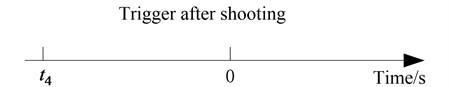
Fig. 5Sketch map of shot exit time for the voltage pulse time signal of muzzle flame

Therefore, on the curve can be obtained as follows: At first, play back the sequence of images conveyed from high speed digital camera, (the time when the muzzle flame initiates) on the surface of the high-speed digital image software (notice, is a negative) and (post trigger time of the high-speed digital camera) on (recorded by the data collector) can be obtained, then:
Similarly, the way to ensure the time when the band of projectile leaves muzzle from the curve of data acquisition is as follows. Play back the sequence of images conveyed from high speed digital camera, (the time when the band of projectile leaves muzzle) can be obtained on the surface of the high-speed digital image software (notice, is negative time), then:
Specially, , , is the time in timing coordinate system of the data collector and , is the time in timing coordinate system of high-speed digital. Although and are corresponding to the starting point of the muzzle flame appears, the timing of the zero point is different.
As shown in Fig. 5: after a large number of experiments, it’s clear that is on the right and is on the left of the timeline. When the band of projectile leaves muzzle, smoke is belched from the muzzle (the output voltage of optoelectronic sensor caused by the smoke is close to zero). After about 0.3 ms, the muzzle flame appeared and then the area of muzzle flame expands quickly. After that, the output voltage of photoelectric sensor will increase quickly. is the starting point of the rapid-increasing voltage pulse curve.
3. Engineering verification
In order to verify the Eq. (4) and the Eq. (5), a kind of major caliber gun is taken as the object. Single shot and the total number of projectiles is 10, the high-speed digital camera is used to record the process of bullets leaving muzzle. The parameters of high-speed digital cameras are set as follows. The speed of shooting is 10000 frames/s when the resolution is set as 1280 pixel×300 pixels (namely, the time interval between each frame image is 0.1 ms). The data collector is used to record the output voltage signal of optoelectronic sensor and synchronization trigger signal of the high speed digital camera, the sampling frequency is 50 kHz (which means the interval of data is 0.02 ms).
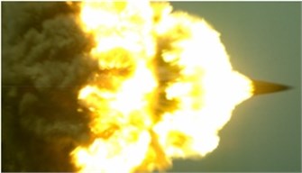
Fig. 6 gives the projectile’s leaving processes from the muzzle recorded by the high-speed digital camera. When the band leaves the muzzle, black fog is blown out from the muzzle brake. After about 0.3 ms, the muzzle flame begins to initiate. From moment that the band of projectile leaves the muzzle to the time that the area of the muzzle flame reaches maximum, it will take about 1.9 ms.
By playing back image sequences of high-speed digital camera and observing on the surface of the high- speed digital image software, the initiation time of muzzle flame can be obtained. From the curve , the time of post trigger of high-speed digital cameras can be gotten. And according to the Eq. (4), the initiation time of muzzle flame on curve can be calculated. is the initiation time of the muzzle time on the curve and also is the starting point of the rapid-increasing parts in voltage pulse curve. It is shown as the point D in Fig. 7(b). Fig. 7(a) shows the whole development of the muzzle flame. And zoom out the increasing segment of the voltage pulse signal, Fig. 7(b) could be received.
Fig. 6Photograph of max. area muzzle flame after projectile leaving muzzle brake
The time (the band of projectile leaves from the muzzle) can be achieved by playing back image sequences of high-speed digital camera and observing on the surface of the high-speed digital image software. Depending on Eq. (5), (the time when the band of projectile leaves from the muzzle) on curve can be calculated. Observing image sequences of high-speed digital camera carefully, it is clear that appears earlier to than . It means the initiation time of muzzle flame is 0.3 ms later than the time when the band of projectile leaves from the muzzle. and in this article means starting point from the muzzle flame once appears and continuously extend to the maximum area of muzzle flame.
According to the results above, when the voltage pulse signal curve obtained by the optoelectronic sensor, the starting point of the voltage pulse is corresponding to the initiation time of muzzle flame, and is earlier than .
As is shown in Fig. 7(b), point “C” on the curve is corresponding to (the time when the band of projectile leaves from the muzzle), and point “D” on the curve is corresponding to (the initiation time of muzzle flame). Point “E” on the curve is corresponding to the time when the area of muzzle flame reaches maximum. The interval between and is 0.3 ms ( 0.3 ms). According to the experiments of different types of gun with same caliber, the interval is about 0.2 ms to 0.4 ms, in this article, the author chooses the average value, 0.3 ms.
Fig. 7The time signal curves of voltage pulse during projectile leaving muzzle
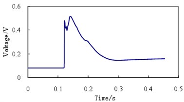
a) The whole process
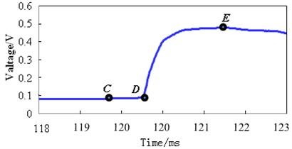
b) The local part
To sum up, due to a lack of advanced testing methods in the past, researchers speculated that the shot exit time is point “D” in Fig. 7(b). But according to the author’s test results, it should be earlier than point “D”. This method mentioned in this paper not only corrects the incorrect view of the traditional method but also accurately determines the shot exit time.
4. Conclusions
1) The measurement of shot exit time is an important research content of gun vibration measurement. Accurate shot exit time is the basis of data processing for muzzle vibration.
2) Using the optoelectronic sensor to get the shot exit time of major caliber gun is an ideal testing method.
3) When the testing curve of the voltage pulse signal obtained by the optoelectronic sensor, it’s obvious that the starting point of the voltage pulse signal is the initiation time of muzzle flame. However, the time when the band of the projectile leaves the muzzle is earlier than the initiation time of muzzle flame.
References
-
Wang Baoyuan, Xu Yaofeng, Zhou Faming, et al. Effect of muzzle vibration on vertical target dispersion. Journal of Vibration and Shock, Vol. 33, Issue 8, 2014, p. 83-87, (in Chinese).
-
Zhang Zhiquan, Zhu Qi, Ding Sheng, et al. A measurement method of muzzle disturbance based on PSD. Journal of Academy of Armored Force Engineering, Vol. 26, Issue 2, 2012, p. 49-53, (in Chinese).
-
Lu Dongqu Inside trajectory index design property analysis of Switzerland double 35 mm towed antiaircraft gun. Acta Sichuan Armamentarii, Vol. 27, Issues 2-2006, 10, p. 13-16, (in Chinese).
-
Wang Baoyuan, Dong Wenxiang, Shao Xiaojun, et al. A method for measuring the aftereffect duration and operating range of projectiles. Acta Armamentarii, Vol. 34, Issue 10, 2013, p. 1329-1333, (in Chinese).
-
Wang Baoyuan, Chao Hongxiao, Shao Xiaojun, et al. Measurement methods for muzzle leaving time of projectile. Acta Armamentanii, Vol. 33, Issue 6, 2012, p. 736-740, (in Chinese).
-
Garner J. M. Muzzle motion measurements for the M198 when fired at 30 and 45 the degrees. Proceedings of the 10th U.S. Army Gun Dynamics Symposium. Austin Texas, USA, 2001, p. 23-26.
About this article

