Abstract
A special calibration cylinder is intended to meet the actual requirement of calibration in defect detection system, and a calibration method is proposed based on this calibration the cylinder. The relative measurement method is adopted in the measurement of inner diameter of cylinder. Through processing the structured light image of inner surface of calibrated cylinder, the relationship between the depth of groove in calibrated cylinder and the distance between the displaced pixels of structured light stripes is obtained, which is used in the calculation of groove depth, and the wear of inner diameter of cylinder is obtained. Experiments show that this method can effectively adapt to the detection environment with a small field of view and weak light, and have higher calibration accuracy, and can meet the actual needs of the detection system calibration.
1. Introduction
Cylinder is a key executive component of gun to realize its power. When fired, the projectile is given initial velocity, rotational speed and flight direction under the action of powder gas [1]. In the course of launching, the inner chamber must bear the harsh environment of high temperature, high pressure and severe friction, which will inevitably lead to defects affecting the artillery technical performance. Therefore, it is particularly important to inspect the inner chamber of artillery regularly and discover the hidden danger in the inner chamber of artillery in time. At present, the detection methods of gun bore defects are mainly caliper method and peep chamber method. Although these methods can detect and judge the inner bore defect to a certain extent, they have some shortcomings, such as low detection efficiency, high probability of misjudgment, easy to cause secondary damage and so on.
Structured light detection technology is a machine vision detection method. It uses image and structured light source measurement technology to analyze the unknown physical information through the geometric information of the known illumination light source [2-4]. Compared with the traditional detection technology, it gets the advantages of non-contact, high precision and high efficiency. In structured light detection technology, the combination of laser and camera is called visual sensor. It is the main of structured light detection technology. The sensor model and model parameters will directly determine the accuracy of the detection system. Therefore, the rapid and accurate calibration of visual sensors is the basis for accurate detection of structured light.
For the calibration of the vision sensor, it can be divided into camera parameter calibration and system structure parameter calibration [5, 6]. At present, the most widely used camera parameter calibration method is based on coplanar reference object calibration method proposed by Zhang Zhengyou [7]. For the calibration of the sensor's structural parameters, there are methods such as wire drawing calibration and tooth profile calibration [8]. Because the working environment of the bore defect detection system has the characteristics of a small field of view and weak light, the traditional calibration method has great limitations [9, 10].
In this paper, a calibration method suitable for bore defect detection system is proposed, and a special three-dimensional target is designed. Using of feature points on the target, the camera parameters can be calibrated quickly. On this basis, the system structure parameters can be calibrated effectively by combining the distance constraints and angle constraints of the target feature points.
2. Detection system composition and working principle
The light path principle of the gun interior defect detection system based on structured light is shown in Fig. 1.
Fig. 1Optical path schematic diagram of detection device
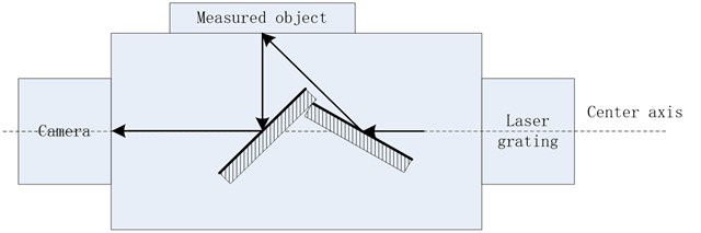
There are two mirrors inside the measuring device. The angle between the left reflector and the horizontal direction is 45°, and the angle between the right reflector and the horizontal direction is 22.5°. The laser grating is incident horizontally on the right reflector, and then at an angle of 45° to the detected object. The reflected light is then illuminated vertically on the left reflector and is incident horizontally on the camera for imaging. In this design, the laser grating and the camera are mounted on the same axis, which ensures the minimum radial dimension of the detector and facilitates the detection of the detector in the narrow space of the artillery.
The main components of structured light detection system include laser, object under test, camera and computer. The laser emits a parallel beam of structured light, which carries the characteristic information of the inner chamber with the bright area formed by the interception of the inner chamber of the gun. The main task of the camera is to get the image which contains the feature information of the bore. It is transmitted with the computer by cable, so that the image taken can be transmitted to the computer for further processing.
3. Calibration principle
The calibration of the structured light detection system takes the form of determining the parameters of each part of the system, and it is also the basis for the system to complete the predetermined function and achieve the predetermined accuracy [11-13]. According to the different calibration objects, the detection system is separated into camera calibration and structural light parameter calibration.
3.1. Design and manufacture of calibration cylinder
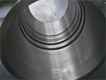
Rifling is a spiral groove which is processed on the surface of the cylinder and has a certain inclination angle with the axis of the cylinder. Grooves with different sizes and different arrangement patterns are processed in the calibration cylinder. The purpose is to show the various characteristics of grooves in the image of extraction according to different needs. Fig. 2 is a calibrated cylinder made of four sets of grooves in the calibration cylinder. The first two sections are all stepped grooves with 4 and 5 steps respectively, and the height of each step groove is 1mm. The latter two sections are groove arrays with the same dimension and equal spacing along the axis direction, with the width of 3 mm and the depth of 1 mm and 2 mm, respectively.
Fig. 2Optical path schematic diagram of detection device
3.2. Camera calibration
The calibration of camera parameters can be summarized as the process of calculating camera parameters from the world coordinates of feature points and the image coordinates of the obtained calibration images. The basic idea is to extract the pixel coordinates of the feature points from the image obtained by the camera through the method of feature extraction, and to solve the camera parameters with the camera model. Because the parameters needed to be calibrated are more, the two step method is utilized to complete the calibration.
The first step is to calculate the image coordinates after the distortion by the distortion model:
Among them, 1, 2, 3,..., and is the calibration feature point.
Then use radial constraints to establish equations, as shown in Eq. (2):
Finally, we compute the , and by using the orthogonality of the R matrix.
The second step is to first solve the and by using the following formula, as shown in Eq. (3):
Then Levenberg-Marquardt algorithm is used to optimize the parameters. When the parameters are optimized, only the minimum of Eq. (4) is required, and the values of , , and are the optimal values:
3.3. Calibration of structured light parameters
The point of intersection between the light plane and the calibration block is selected as the control point, which is expressed by C1-CN. Since the coordinates of the feature points in the image is known, the coordinates of the control points can be obtained according to the invariance of the cross ratio:
where represents the distance between two points on the image, represents the distance between two points in the space.
On the basis of solving the coordinates of control points, the equation of light plane can be obtained by using any three non-collinear control points. At the same time, the least squares method can be used to fit the equation of light plane for more than 3 points.
4. Calibration experiment
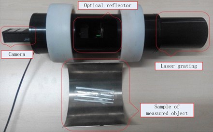
In order to verify the effectiveness of the calibration method, the calibration experiment of the gun inner chamber defect detection system was carried out. The experimental equipment, as shown in Fig. 3, mainly includes the prototype of the detection system and the calibration board. The CM-140 CCD camera from JAI company is selected as the imaging element, the resolution of the camera is 1392×1040, and the laser grating with 250 mW power is selected as the light source.
Fig. 3Calibration system for testing system
In the calibration experiment, the calibration board is placed in different positions within the field of view of the camera. To ensure the reliability of the experiment, 15 positions are used to calibrate the camera parameters and the structure parameters of the detection system.
4.1. Calibration of camera internal parameters
When calibrating the internal parameters of the camera, the first 14 positions are used to calibrate the internal parameters of the camera. Finally, the calibration results are substituted into the coordinates of the fifteenth position and compared with the actual coordinates. The accuracy of calibration is evaluated by the RMS error evaluation method and the method proposed in document [14]. The results are shown in Table 1.
As can be seen from Table 1, the calibration error is slightly larger than the reference value. The main reason is that the calibration plate used in this paper is smaller, more sensitive to various factors of calibration environment, and more external interference. And the calibration board in the production process due to the limitations of processing technology, there are errors to a certain extent. The calibration results will also have a greater impact.
Table 1Calibration results and errors of camera internal parameters
/ mm | / mm | / pixel | / pixel | RMS | ||||
Calibrated value | 1960.568 | 1985.256 | 649.346 | 547.658 | 88.90 | –0.0856 | 0.193 | 0.085 |
Reference value | 1970.478 | 1973.910 | 666.158 | 543.303 | 89.99 | –0.091 | 0.168 | 0.098 |
Error | 0.503 % | 0.572 % | 2.52 % | 0.801 % | 1.21 % |
4.2. Calibration of structural parameters of detection system
After the camera internal parameters are calibrated, the parameters of the system structure are calibrated using the obtained results. Combined with the calibration values of camera parameters, the accurate model of the system can be obtained. Table 2 is a comparison between the coordinate values of the characteristic points calculated by the calibrated model and the actual coordinate values, which can be used as a judgment index of the measurement accuracy of the system.
It can be seen from Table 2 that the calibration method presented in this paper have higher calibration accuracy. In the process of calibration experiment, random error will inevitably be introduced, and the quality of structured light source, the error of calibration image feature extraction and other aspects will have a certain impact on the calibration results page.
Table 2Measurement accuracy analysis of defect detection system
Characteristic points | Distance standard value /mm | Distance calculation value /mm | Absolute error | Relative error |
AB | 4 | 4.037 | 0.037 | 0.925 |
AC | 8 | 8.069 | 0.069 | 0.863 |
AD | 12 | 12.125 | 0.125 | 1.042 |
BC | 4 | 4.103 | 0.103 | 2.575 |
BD | 8 | 8.057 | 0.057 | 0.713 |
CD | 4 | 4.092 | 0.052 | 1.3 |
4.3. Image acquisition of calibration cylinder
Fig. 4(a) A structured light image is captured in the smooth area of the calibration cylinder. It can be seen that there are many noise points in the image. Fig. 4(b) Structured light images taken from the calibrated cylinder stepped groove region show a significant truncation and offset of the structured light fringes, which are modulated by a sudden change in the depth of the cylinder surface at the stepped groove due to the oblique projection of structured light from the structured light projector onto the inner surface of the cylinder. The three non striped black area in the image is the area where the structural light cannot be projected due to the depth of the groove.
Fig. 4Calibration system for testing system
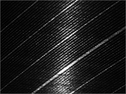
a) Smooth region
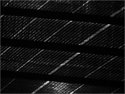
b) Ladder groove area
5. Conclusions
Aiming at the actual requirement of calibration in bore defect detection system, a special calibration cylinder is designed and a calibration method is proposed. The calibration cylinder can effectively determine the camera parameters, structure parameters and fit the light plane equation of the detection system, and the proposed method can calibrate the detection system with high accuracy. Next, we plan to analyze the three-dimensional shape of the object based on the calibrated detection system.
References
-
Ding Chao, Tang Liwei, Cao Lijun, et al. Height difference detection of barrel rifling based on structured light. Optics and Precision Engineering, Vol. 25, Issue 4, 2017, p. 545-553.
-
Hao Huadong, Shi Haolei, Wu Zenan, et al. Research on precision measuring method of small shaft coaxiality based on structured light 3D scanning technology. China Measurement and Test, Vol. 44, Issue 2, 2018, p. 36-40.
-
Barone S., Paoli A., Razionale A. V. Shape measurement by a multi-view methodology based on the remote tracking of a 3D optical scanner. Optics and Lasers in Engineering, Vol. 50, Issue 3, 2012, p. 380-390.
-
Liu Guanzhou, Wang Ying, Ding Chao, et al. Research on structured light phase error compensation based on phase mapping. China Measurement and Test, Vol. 44, Issue 4, 2018, p. 26-30.
-
Zou Yuanyuan, Zhao Mingyang, Zhang Lei Direct calibration method of laser stripe vision sensor based on gauge block. Chinese Journal of Lasers, Vol. 41, Issue 11, 2014, p. 195-200.
-
Liu Zhen, Shang Yanna Novel calibration method for stereo vision sensor using flexible target. Acta Optica Sinica, Vol. 33, Issue 3, 2013, p. 205-211.
-
Chi Dexia, Wang Yang, Ning Liqun, et al. Experimental research of camera calibration based on Zhang’s method. Journal of Chinese Agricultural Mechanization, Vol. 36, Issue 2, 2015, p. 287-289+337.
-
Wang Yao, Peng Xiurong, Lin Chunwen Nondestrutive inspection of the inside walls of small- diameter pipelines for corrosion. Nondestructive Testing, Vol. 26, Issue 5, 1999, p. 54-59.
-
Raghu K., Glen B. Improving 3D surface measurement accuracy on metallic surfaces. Proceedings of SPIE, Bellingham, WA, 2005, p. 618-624.
-
Dong Jianmin, Li Dongjing Accurate calibration algorithm for structure light system based on line fitting. China Measurement & Test, Vol. 41, Issue 8, 2015, p. 8-93.
-
Shen Bobo, Xu Jialu, Kong Ming Height measurement for air conditioner four-way reversing valve based on line structured light. China Measurement and Test, Vol. 44, Issue 3, 2018, p. 33-37+43.
-
Ding Chao, Tang Liwei, Cao Lijun, et al. 3D reconstruction of deep hole inner surface using structured light. Infrared and Laser Engineering, 2018, (in Chinese).
-
Li Yuehua, Zhou Jingbo, Liu Lijian Research progress of the line structured light measurement technique. Journal of Hebei University of Science and Technology, Vol. 39, Issue 2, 2018, p. 115-124.
-
Chen Ying, Yu Pu Photoelectric technique for the automatic non- destruction test of the inner surface of a pipe. Optoelectronic Technology, Vol. 21, Issue 1, 1999, p. 261-262.
About this article

