Abstract
The braking force of the muzzle brake affects not only the strength of the connection thread of the muzzle brake, but also the vibration response of the artillery structure. Due to the complex formation process of the braking force of the muzzle brake, the current theoretical calculation method is used to estimate. This paper presents an experimental measurement method for artillery force of muzzle brake, which describes the measurement principle and deduces the calculation formula. The small-caliber cannon with muzzle brake is selected as the test object. A verification shooting experiment is carried out to obtain the size of the artillery force of the muzzle brake. The measurement values of the artillery force are basically consistent with the theoretical ones. The measurement method and principle introduced in this paper can be applied in the actual artillery force measurement of the muzzle brake. In this paper, the strain measurement principle is used to complete the experimental test of the braking force of the muzzle brake. This paper innovatively proposes a new method for testing the braking force, which has the advantages of simple operation, no need to manufacture special tooling, and low cost.
1. Introduction
The muzzle brake is used to reduce the impulse of gunpowder gas to the recoil part in the after-effect period. By controlling the speed and direction of the gunpowder gas in the after-effect period, the momentum transfer method is used to reduce the impulse of the combined force of the artillery, and the purpose of reducing the recoil kinetic energy to reduce the force of the artillery frame and reduce the mass of the artillery frame to improve the maneuverability of the artillery is achieved. It also has positive significance for reducing the vibration of artillery. According to the principle, the muzzle brakes can be divided into impact and anti-impact muzzle brakes. Small-caliber cannons often use anti-impact muzzle brakes. After the bullet passes out of the muzzle, the high-pressure gunpowder gas in the pipe enters the chamber with a smaller inside diameter, the expansion is small, the pressure is still high, most of the gas suddenly expands through the lateral expansion orifice, and is ejected at a high speed to form a reverse thrust (or braking force [1]), so that the body forward, and a small amount of gas out of the central bullet hole [2]. The greater the braking force, the smaller the combined force of the artillery forces acting on the recoil structure, the smaller the vibration response of the artillery structure, and the better the artillery firing stability [3-8].
The braking force of the muzzle brake can be obtained by testing parameters such as the muzzle brake efficiency. The traditional test method for muzzle brake efficiency is to use a free recoil test bench with high cost and complicated test procedure to achieve the parameters such as free recoil speed [9]. The literature [10] proposes a new method called the contrast method for testing the muzzle brake recoil efficiency. Under the full charge condition of the artillery gun, two different muzzle brakes are installed to perform the recoil test. Through the measurement and calculation, the squat resistance-rear displacement curve is obtained, and the squat resistance is obtained by integrating it. According to the relationship between the two squat resistances in the two working conditions, the muzzle brake efficiency can be calculated and the artillery shooting test is passed verification. This paper [11] proposes a muzzle brake test method that uses medium-pressure compressed air close to normal temperature instead of gunpowder gas and can realize digitization and automatic control. The muzzle brake is geometrically similar to the same caliber size muzzle brake for testing.
The muzzle brake relies on the thread and the body tube connection. The magnitude of the retraction force of the muzzle brake affects the strength of the muzzle connection thread, which affects whether the muzzle brake can be reliably connected. Currently, a commonly used calculation method is used to estimate the braking force of the muzzle brake. According to the literature [12], in the after-effect period, the formula for calculating the total force of the artillery with the muzzle brake is:
In the Eq. (1), is the combined force of the artillery when without muzzle brake; is the impulse characteristic of the muzzle brake.
The formula for calculating the impulse characteristic of the muzzle brake is:
In the Eq. (2), is the bullet weight: is the powder gas interaction coefficient, estimated by empirical formula , is the empirical coefficient, is the initial speed of the bullet; is the charge amount; is the muzzle brake efficiency.
Under the condition of known parameters , , , , the Eq. (2) can be used to calculate the impulse characteristic of the muzzle brake . Thus, in the after-effect period, the combined force formula of the Artillery with the muzzle brake is:
The braking force of the muzzle brake can be calculated according to Eq. (3):
Under the condition of unknown parameters , , , , the experimental method can be used to obtain the braking force of the muzzle brake. The purpose of this paper is to propose an experimental method for testing the braking force of the muzzle brake, describe the test principle of the system’s braking force, derive the calculation formula used in the experimental test process, conduct the braking force of the actual artillery muzzle brake, and give test results.
2. The principle of test
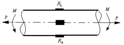
In this paper, the strain measurement principle is used to complete the experimental test of the braking force of the muzzle brake. Four measuring points are symmetrically selected on a certain cross section of the outer surface of the barrel near the muzzle brake, and a unidirectional strain gauge is attached to each measuring point, and the direction of the sensitive grid is along the axis of the tube, as shown in Fig. 1. The strain gauges on the upper and lower surfaces form a bridge system, and the strain gauges on the left and right surfaces form another bridge system. By averaging the strains obtained by the two bridge systems, the axial strain of the barrel caused by the muzzle brake can be obtained, and the braking force can be obtained. In Fig. 1, represents the breaking force along the axis of the body tube, and represents the bending moment of the body tube.
Fig. 1Sketch of position of measuring point for strain
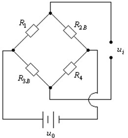
As follows, the axial tension strain of the bridge system composed of the upper and lower surface measuring point strain gauge is taken as an example to illustrate the derivation process of the formula for calculating the back force. The upper surface strain gauge is marked as , and the lower surface strain gauge is marked as . In order to eliminate the influence of temperature, two pieces of temperature compensation sheets are pasted on the unstressed members, labeled as and , respectively. Use , , , and to complete the bridge connection as shown in Fig. 2. Where and are working pieces, is a constant voltage, and is the output voltage at which the dynamic strain gauge operates (corresponding to the strain test value).
During the post-effect period, the body tube stress mainly includes the braking force along the axis of the body tube, the bending moment received by the body tube, and the stress caused by the temperature. The temperature stress can be eliminated by temperature compensation. The strain caused by the brake force P on the upper and lower outer surfaces is marked as and . The strain caused by the bending moment on the upper and lower outer surfaces is marked as and . The strain caused by the temperature on the upper and lower outer surfaces is denoted by and , and the strains corresponding to the temperature compensating sheets and are and , respectively. According to the symmetrical characteristics of the body tube structure and the symmetry characteristics of and :
According to the working principle of the bridge shown in Fig. 2 and the Eq. (5) and Eq. (6), the relationship between output voltage and strain is [13]:
In Eq. (7), is the sensitivity coefficient of the strain gauge.
It can be seen from Eq. (7) that the strain due to temperature and bending moment will not appear in the equation, but the strain reading corresponding to the brake force is divided by 2.
Solved from Eq. (7), there is:
Assume that the cross-sectional area of the strain measuring point is , the elastic modulus of the body material is , and the stress caused by the braking force of the muzzle brake is , then the braking force of the muzzle brake is:
In order to eliminate the test error, according to the same method and principle, the strain gauge can be attached to the symmetrical position of the left and right outer surfaces of the barrel near the muzzle brake, and the axial tensile strain can also be obtained. The left and right pull strain and the upper and lower pull strain are averaged and recorded as , so the Eq. (9) can be rewritten as:
Eq. (10) gives the calculation formula of the strain test principle to find the braking force of the muzzle brake. Therefore, in the experimental test, as long as the axial tensile strain of the body tube is obtained, and the cross-sectional area of the body tube at the measuring point is measured, the braking force exerted on the body tube by the muzzle brake at the time of shooting can be obtained.
Fig. 2Sketch of working principle for circuit bridge
3. Experiment procedure
In order to test the feasibility of the method, a small-caliber gun with a muzzle brake is used as the test object. Four measuring points are symmetrically selected from the outer surface of the barrel near the muzzle brake, and the one-way strain gauge is pasted and temperature compensated. Three sets of shooting experiments were used to average the results in a single shot.
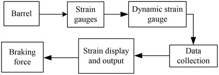
After measurement, the position of the strain measuring point, the cross-sectional area of the body tube is 0.003 m2, the average value of the tensile strain is 64.4 με, and the elastic modulus of the body tube material is 2.1×10¹¹Pa, then the axial tensile force test of the barrel caused by the muzzle brake of the test artillery(braking force) is tested. The value is 40572 N. The theoretical calculation value of the axial tensile force of the test tube during the shooting process is 41985 N, and the experimental test value is basically consistent with the theoretical calculation one. The schematic diagram of the test scheme is shown in Fig. 3.
Fig. 3Sketch of measuring project of braking force for muzzle brake
4. Measurement uncertainty analysis
The error of the braking force of the muzzle brake is mainly derived from: 1) Strain measurement; 2) the cross-sectional area of the body tube measurement.
The error caused by the first factor is 1 με, which is a uniform distribution. The relative standard uncertainty introduced by this factor is:
The area error caused by the second factor is 0.00003, which is a uniform distribution. The relative standard uncertainty introduced by this factor is:
The relative measurement standard uncertainty of the braking force of the muzzle brake is:
Under normal circumstances, the maximal braking force of the muzzle brake is 50000 N, and the standard measurement uncertainty of the movement time in the projectile is:
The confidence level is 99.7 %, the factor 3, and the uncertainty of the motion time expansion of the projectile is obtained:
In summary, the uncertainty of the braking force of the muzzle brake is 799.5 N, which is only about 1.5 % of the mean value, which satisfies the test error of the braking force of the muzzle brake.
5. Conclusions
In order to study the influence law of the braking force of the muzzle brake on the thread strength of the body tube and the influence of the vibration response of the artillery, this paper proposes a test method for the braking force of the muzzle brake to describe the test principle, derived the calculation formula. For the practicality of the method, a small-caliber gun with a muzzle brake was selected as the test object, and the verification shooting experiment was carried out, and the braking force of the muzzle brake was obtained. The test value of the experimental force is basically consistent with the theoretical calculation value. The test method and test principle of this paper can be applied in the measurement of actual artillery brake.
References
-
Wang Baoyuan, Heng Gang, Zhou Faming, et al. Experiment study of the relation between muzzle screw structure and its strength. Journal of Gun Launch and Control, Vol. 36, Issue 4, 2015, p. 82-85, (in Chinese).
-
Wang Jingjun, Hao Xinpeng Gun Introduction. The Publishing House of Ordnance Industry, Beijing, 1992, p. 80-81, (in Chinese).
-
Wang Baoyuan, Heng Gang, Zhou Faming, et al. Progresses of a Measurement Technology of Gun. National Defense Industry Press, Beijing, 2011, p. 1-10, (in Chinese).
-
Wang Baoyuan, Shao Xiaojun Summarization of the measurement method for muzzle vibration responses. Journal of Gun Launch and Control, Vol. 3, 2010, p. 112-116, (in Chinese).
-
Chen Yanhui, Guo Min, He Zong Ying, et al. Muzzle vibration test method and practice. Journal of Gun Launch and Control, Vol. 1, 2010, p. 80-83, (in Chinese).
-
Wang Baoyuan, Xu Yaofeng, Zhou Faming, et al. Effect of muzzle vibration on vertical target dispersion. Journal of Vibration and Shock, Vol. 33, Issue 8, 2014, p. 83-87, (in Chinese).
-
Li Kuiwu, Wang Baoyuan Research Methods of Gun Firing Dispersion. National Defense Industry Press, Beijing, 2012, p. 1-42, (in Chinese).
-
Wang Baoyuan Summarizing on research of firing dispersion of medium and large caliber artillery. Journal of Gun Launch and Control, Vol. 36, Issue 2, 2015, p. 82-87, (in Chinese).
-
Shi Chunming, Yan Liuhai, Liu Wanyu Test method of muzzle brake efficiency on gun carriage. Journal of Gun Launch and Control, Vol. 3, 2007, p. 47-49, (in Chinese).
-
Wang Kai, Zhao Junli, Fan Shewei A new test method of muzzle brake efficiency. Journal of North University of China (Natural Science Edition). Vol. 35, Issue 6, 2014, p. 676-680, (in Chinese).
-
Chen Mingliang Research on the Test Device of a New Muzzle Brake. Nanjing University of Science and Technology, Nanjing, 2013, (in Chinese).
-
Zhang Yue Lin Design of Recoil System for Gun. National Defense Industry Press, Beijing, 1984, p. 80-85, (in Chinese).
-
Xu Hao Mechanical Design Handbook. China Machine Press, Beijing, 2003, p. 5-43, (in Chinese).
About this article

