Abstract
The CFD simulations are carried out for the flows in a helical gas-liquid separator, which is installed at the inlet of the electric submersible pump (ESP) to separate gas from gas-liquid mixture and keep the efficiency of the pump. The effects of mass flux, curvature and helix angle on two-phase pressure drop have been investigated. Through theoretical analysis and numerical simulation, it is found that the mass flux of two-phase flow and the curvature of spiral passage have influence on pressure drop, while the spiral angle has little effect on pressure loss.
Highlights
- A CFD model for the pressure loss of gas-liquid two-phase flow in a helical channel is given.
- The influence of structure of helical channel on the pressure loss was studied by numerical simulation method, and the reliability of the numerical simulation was verified by theoretical analysis.
- The variation of helix angle has little effect on the pressure drop, and the variation of curvature causes a change in the centrifugal force, which will have a significant effect on the pressure drop.
1. Introduction
The gas-liquid separator is widely used in artificial lifting system, mainly installed at the entrance of centrifugal pump, sucker rod system and screw pump and so on, in order to separate as much gas as possible from the mixed flow of oil and gas underground. The separation of gas and liquid occurs in the air chamber of the separator. The guide vanes at the entrance of the separator can convert the tangential flow into axial flow, thus reducing the flow loss. Compared with the straight tube, the curvature of spiral tube, helix angle and the number of helical coils may affect the flow characteristics of the fluid. Therefore, many researchers have also carried out investigations on them. Chen and Guo [1, 2] studied the pressure loss of oil, gas and water in the spiral tube through the experimental method, and gave the calculation formula of pressure drop under the test condition. A series of studies on flow morphology and pressure loss in spiral channels with rectangular cross sections were carried out by Xia et al. [3]. It is obvious that the pressure loss of gas-liquid separator through the spiral channel with rectangular cross section is predicted by the CFD method, which has some guiding significance for the optimization and structure design of the separator.
2. Theoretical analysis and numerical calculations
2.1. Characteristics of helical pipe
As shown in Fig. 1(a) and (b) respectively show the geometric structure of the spiral separator and the main parameters of the spiral channel. The separator is placed along the vertical direction. The hub and casing have diameters of and , respectively. The distance between two adjacent turns is defined as pitch . The ratio of hub diameter to the casing diameter is defined as curvature . The Dean number is defined as , which is used to characterize the flow in helical pipe, where Re is the Reynolds number . The properties of the fluid used in the simulation is shown in Table 1.
Table 1Properties of the fluid used in the simulation study
Properties | Air | Water |
Density | 1.225kg/m3 | 1.7894×10⁻⁵kg/m·s |
Viscosity | 998.2kg/m3 | 0.001003 kg/m·s |
Fig. 1The structure of a helical separator with its main geometrical parameters
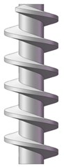
a)
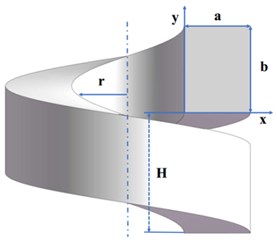
b)
2.2. Boundary conditions
The wall is provided as a fixed wall surface, and the velocity inlet and pressure outlet serve as boundary conditions for fluid to enter and exit the separator, respectively. The discretization of the continuity equation and the momentum equation uses a QUICK method. The calculation of turbulent dissipation rate, Reynolds stress and turbulent flow energy is based on the second-order upwind.
2.3. Numerical model
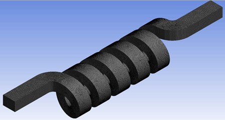
The algebraic slip mixing model can reflect the relative slip and rotation of the two-phase flow, and the numerical simulation of the gas-liquid separation of the spiral channel is carried out by the finite volume method. Fig. 2 shows the 3D CFD model for calculating two-phase flow after mesh generation. In this study, the RNG κ-ε turbulence model proposed by Yakhot and Orszag [4] is adopted.
Fig. 2Whole grid of the helical channel used for analysis
Continuity equation:
Momentum conservation equation:
The study on the independence of grid when dividing the grid was conducted. When the interval size of grid is set to 0.0015, it has little influence on the calculation results, so as to ensure the reliability of the calculation results.
3. Results and discussion
3.1. Comparison between numerical prediction and formula
The total pressure drop in gas-liquid two phase straight flow has three main components of frictional, acceleration and hydrostatic pressure drop. As shown in Eq. (3):
The gravity, acceleration and frictional pressure drop in a vertical pipe are shown as followed equations, respectively:
where is the two-phase mixture flow rate, represents the liquid phase and represents the gas phase.
The separate flow model of two phase frictional pressure drop is also determined by two phase friction multiplier. Pressure drop is usually written as:
The liquid only friction factor agrees well with the results in an earlier study for a helically coiled flow, as is presented by Ito [5]:
Taylar [6] has studied the two-phase flow pressure drop in the small bending radius helical tube by the experimental method, and based on the uniform flow formula with correction coefficient, the friction pressure drop formula was written as follows:
where 2.19, –3.61, 7.35, and –5.93.
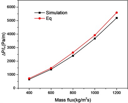
Fig. 3 gives a comparison between the simulated pressure drops and those obtained by Eqs. (8)-(11). Pressure drops measured by the Fluent agree well with those estimated by using Taylar et al. formula although with a maximum error of 19.3 %.
Fig. 3Comparison of present predictions with Eqs. (8)-(11)
3.2. The effect of structure parameters on pressure loss
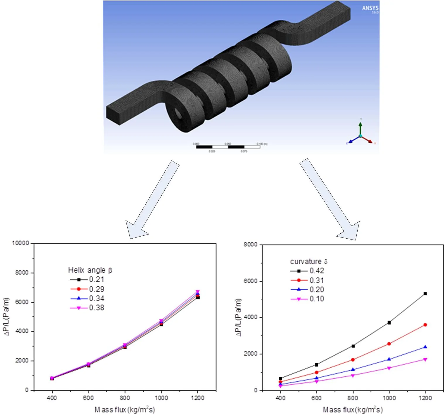
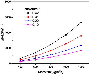
The effects of curvature and spiral angle on pressure loss are studied by numerical simulation. Fig. 4 shows pressure distribution at different sections in the flow channel, the entrance presenting a high pressure distribution. When the fluid approaches the outlet of the screw, pressure on the left and right sides of the screw channel is evenly distributed. Fig. 5 shows that for the research object of this article, when the helix angle changed, the pressure loss is almost unaffected. However, when the curvature of the helical channel changes, the centrifugal forces acting on the gas and the liquid have a great influence and the separation between the gas and the liquid is accelerated. It also generates more energy loss, as shown in Fig. 6.
Fig. 4The predicted pressure distribution of air-water flow at different axis location
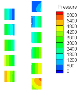
Fig. 5The effect of helix angle on pressure drop
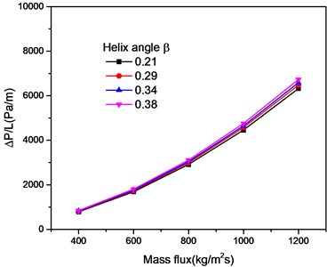
Fig. 6The effect of curvature on pressure drop
4. Conclusions
The effects of curvature and spiral angle on pressure loss at different inlet velocity were studied by numerical simulation and theoretical analysis. It is found that the change of helix angle has little effect on pressure drop, while the change of curvature will lead to the change of centrifugal force on gas-liquid two-phase flow, which will have a significant impact on pressure drop.
References
-
Chen X., Guo L. Flow patterns and pressure drop in oil–air–water three-phase flow through helically coiled tubes. International Journal of Multiphase Flow, Vol. 25, 1999, p. 1053-1072.
-
Jayakumar J. S., Mahajani S. M., Mandal J. C., et al. CFD analysis of single-phase flows inside helically coiled tubes. Computers and Chemical Engineering, Vol. 34, Issue 4, 2010, p. 430-446.
-
Xia G. D., Liu X. F. An investigation of two-phase flow pressure drop in helical channel. International Communications in Heat and Mass Transfer, Vol. 54, 2014, p. 33-41.
-
Yakhot V., Orszag S. A. Renormalization group analysis of turbulence. Journal of Scientific Computing, Vol. 1, Issue 1, 1986, p. 3-51.
-
Murai Y., Yoshikawa S., Toda S., et al. Structure of air-water two-phase flow in helically coiled tubes. Nuclear Engineering and Design, Vol. 236, Issue 1, 2006, p. 94-106.
-
Taylor P., Ju H., Huang Z., Xu Y., Duan B., Yu Y. Hydraulic performance of small bending radius helical coil-pipe hydraulic performance of small bending radius helical coil-pipe. Nuclear Technology, Vol. 38, 2001, p. 826-831.
Cited by
About this article

The authors gratefully acknowledge the support from Young teacher special project of Ningde Normal University (Grant Nos. 2017Q104 and 2018Q102), Major training project of Ningde Normal University (Grant No. 2017ZDK18), Education and Research Project for Young and Middle-aged Teachers in Fujian Province (Grant Nos. JT180597 and JT180601).
