Abstract
When the two phases pass through the bifurcated pipe of the T-shaped pipe, the ratio of the two-phase of the main pipe and the branch pipe generally changes. This paper uses FLUENT to simulate the separation characteristics of a two-phase mixture of high-viscosity oil and water in a T-pipe, and studies the effect of different structures (the height of the branch pipe, the number of branch pipes, and the spacing of the branch pipes) on the separation characteristics. The results show that the number of branch pipes and the spacing of the branch pipes have a great influence on the separation efficiency of the two phases.
Highlights
- T-junction
- two-phases separation
- Numeral Calculations
1. Introduction
The T-shaped pipe is composed of a straight pipe and a branch pipe which are vertically orthogonal, and is often used as a pipe branch in the fluid conveying pipe system [1, 2]. When the two-phase medium enters the T-shaped branching pipe from one end of the main pipe, the main pipe is downstream and branches. The ratio of the oil and water phases in the pipeline generally changes, which is called phase distribution [3, 4]. In biomedical science, the phase distribution of the T-tube main tube and the branch tube is also utilized for drainage, such as the use of a T-tube for bile drainage. In addition, since the arrangement of the main blood vessels and the branch vessels in humans is similar to the T shape, studying the phase distribution phenomenon of the T-shaped tubes has a great effect on biomedicine. Therefore, this paper uses FLUENT to carry out numerical simulation of the separation characteristics of high water-containing and high-viscosity oil-water mixtures passing through T-pipes, and studied the T-pipe structure (branched pipe height, number of branch pipes, branch pipe spacing) for separation. The influence of characteristics provides some theoretical basis and reference for industrial applications.
2. Numerical simulation
In this paper, with the CFD commercial software FLUENT, the influence of different branch pipe spacing, branch pipe height and number of branch pipes on phase distribution is analyzed. At the same time, this simulation ensures the reliability of the simulation through multiple sets of experiments and grid-independent detection.
2.1. Geometric model and meshing
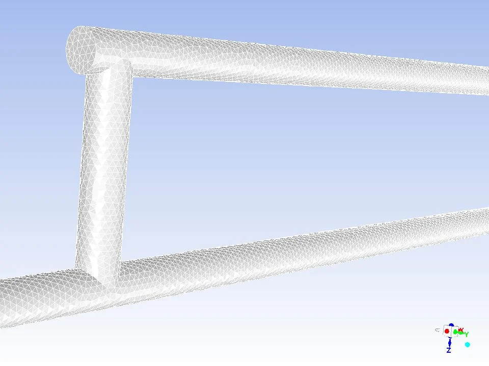
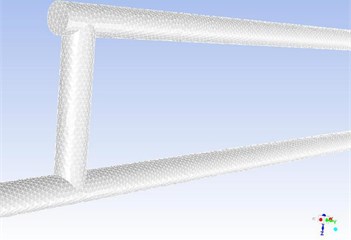
The geometric model is shown in the Fig. 1 and The WorkBench is used to divide the T-tube into grids. First before the solid geometry model built by Solidworks imports and subdivides the mesh. Mesh division as shown in Fig. 2 The left port of the geometric model is the inlet of the oil-water mixture. After the oil-water mixture flows in, after the front inlet section is stabilized, the horizontal and vertical diversions are carried out through the intersection of the main pipe and the branch pipe.
Fig. 1Geometric model

Fig. 2Meshing
2.2. Boundary conditions and model settings
In order to study the separation characteristics of high water content oil-water mixture in T-pipe, the simulated case is a 93 % water content oil-water mixture. The physical properties of oil and water two phases are shown in Table 1:
Table 1Physical properties of oil and water (20 °C)
Fluid | Density (kg/m3) | Viscosity (kg/ms) |
Water | 998.2 | 0.001003 |
Oil | 900.5 | 0.200000 |
The boundary condition at the inlet is set to be the velocity inlet. In order to make the oil-water mixture a stable mixed stratified flow, the velocity inlet at the inlet is set to 0.3 m/s according to Trallero’s [5] experimental flow rate profile. The boundary condition at the outlet is out flow, and the split ratio of the two outlets is defined as 0.5:0.5.
Considering the particle diameter of the oil phase is relatively large, there is an interaction between the oil phase molecules and the water molecules [6, 7], so the Eulerian model is chosen. The Euler model considers the two phases as a continuous medium that penetrates each other and takes into account the interaction between the two phases.
According to the mass conservation law, the continuity equation is:
The conservation equation for the momentum can be expressed by:
In case the particle diameter is relatively large, the following lift force must be taken into account:
The exchange coefficient for the oil/water two-phase flow can be written in the following general form:
where is the particulate relaxation time and is the drag function, defined as:
where is the particle size, is the kinetic viscosity, is the drag coefficient and is the Reynolds number.
For the stratified flow and the two-phase density ratio close to 1, the mixture - turbulence model can be used to calculate the turbulence characteristics [8, 9]. and equations are follows:
where, the mixture density and the mixture velocity are defined as:
The turbulent viscosity and the production of turbulence kinetic energy , can be computed from:
3. Results
Because the oil-water mixture has a low oil content, in order to more clearly show the separation efficiency, the separation efficiency is defined as:
represents the oil phase flow at the oil phase outlet, represents the oil phase flow at the water phase outlet, represents the oil phase flow at the inlet.
3.1. Number of branch pipes
The initial setting of the pipe diameter 150 mm, in order to explore the influence of the number of branches and the separation characteristics, numerical simulation of the T-shaped pipes of 8 sets of different branch pipes respectively, the parameter setting is shown in Table 2.
Table 2Numbers of branch pipes
No. | 1 | 2 | 3 | 4 | 5 | 6 | 7 | 8 |
Number of branch pipes | 1 | 2 | 3 | 4 | 5 | 6 | 7 | 8 |
The results are shown in Fig. 3. In the figure, we can see that the separation efficiency of the oil-water two-phase in the T-shaped pipe increases significantly with the increase of the number of branch pipes.
Fig. 3Separation efficiency under different branch numbers
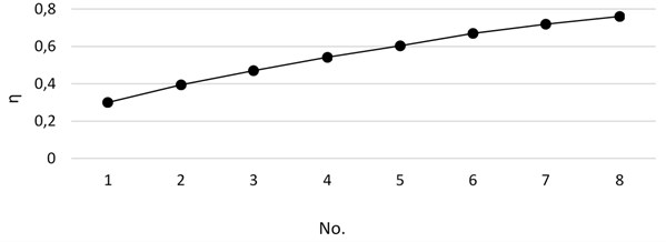
Since the phase distribution of one time does not allow the oil phase to fully enter the upper oil phase outlet pipe, increasing the number of branch pipes can increase the number of phase distributions. The multi-branched pipe can continue to phase-distribute the oil-water mixture after the phase distribution, so that the oil phase that does not enter the upper pipeline in the main pipeline can flow more into the upper oil pipe, thereby improving the separation efficiency of the two phases.
3.2. branched pipe height
In order to make the simulation data more obvious, we use the T-pipe of the 3-branch pipe to simulate the height of the branch pipe. the parameter setting is shown in Table 3. 150 mm, branch pipe spacing is 4D.
Table 3Branched pipe height
No. | 1 | 2 | 3 | 4 | 5 | 6 | 7 | 8 | 9 |
Branched pipe height | 1D | 2D | 3D | 4D | 5D | 6D | 7D | 8D | 9D |
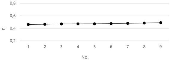
The results are shown in Fig. 4. In the figure, we can see that the separation efficiency of the oil-water two phases did not change significantly with the change of the height of the branch pipe.
This is because the separation effect of the oil-water two-phase is mainly caused by the phase distribution effect, and the branch pipe height has little effect on the phase distribution, and the branch pipe and the main pipe flow do not change due to the change of the branch pipe height. Therefore, the separation efficiency does not have a significant effect as the height of the branch pipe changes.
Fig. 4Separation efficiency under different branched pipe heights
3.3. Branch pipe spacing
In order to explore the effect of branch pipe spacing on separation efficiency, we also set 8 groups. The parameter setting is shown in Table 4 branched pipe height is 4D.
Table 4Branched pipe height
No. | 1 | 2 | 3 | 4 | 5 | 6 | 7 | 8 | 9 |
Branch pipe spacing | 1D | 2D | 3D | 4D | 5D | 6D | 7D | 8D | 9D |
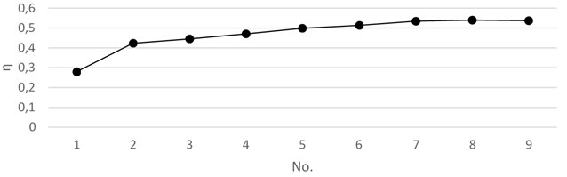
From the Fig. 5, we can see that when the interval between the branch pipes is short, the separation efficiency of the oil-water two phases is not high, even lower than the separation efficiency when the single branch pipe is used. The separation efficiency will increase with the increase of the spacing of the branch pipes. When the branch pipes are separated by a certain distance, the separation efficiency remains basically unchanged. When the branch pipe spacing is from 1D to 2D, there will be a significant increase in efficiency. When the branch pipe spacing is from 3D to 7D, the separation efficiency has a slow increase with the increase of the pitch. After the distance between the branch pipes reaches a certain distance, the separation efficiency of the two phases remains unchanged when the branch pipe spacing is 7D to 9D.
Fig. 5Separation efficiency under different branched pipe spacing
When the oil-water mixture flows through the main pipe and the cross pipe, the flow pattern of the oil-water mixture changes, from the state of the original stratified flow to the other state, and if the interval of the branch pipe is not very long, the state of the oil-water mixture is not very stable. When passing through the next branch pipe, because it is not a state of stratified flow, the phase distribution effect cannot be achieved very well. Therefore, when the interval between the branch pipes is short, the separation efficiency is poor. With the increase of the spacing of the branch pipes, the oil-water mixture has a sufficient distance between the two branch pipes to re-establish the smooth flow of the oil phase and the water phase under the action of gravity, and the flow pattern is changed into a stratified flow.
4. Conclusions
An increase in the number of branch pipes can improve the separation efficiency. The greater the spacing of the branch pipes, the higher the separation efficiency. The height of the branch pipe has little effect on the separation efficiency.
References
-
Yang L., Azzopardi B. J., Belghazi A., et al. Phase separation of liquid-liquid two-phase flow at a T-junction. AICHE Journal, Vol. 52, Issue 1, 2010, p. 141-149.
-
Zheng Zhi Chu, Wu Ying Xiang, Li Qing Ping et al. A study on the combined separator for oil/water/gas mixtures. Shipbuilding of China, Vol. 46, 2005, p. 543-549, (in Chinese).
-
Wren E., Azzopardi B. J. The phase separation capabilities of two T-junctions placed in series. Chemical Engineering Research and Design, Vol. 82, Issue 3, 2004, p. 364-371.
-
Mohamed M. A., Soliman H. M., Sims G. E. Experimental investigation of two-phase flow splitting in an equal-sided impacting tee junction with inclined outlets. Experimental Thermal and Fluid Science, Vol. 35, Issue 6, 2011, p. 1193-1201.
-
Trallero J. L., Sarica C., Brill J. P. A study of oil-water flow patterns in horizontal pipes. SPE Production and Facilities, Vol. 12, Issue 3, 1997, p. 165-172.
-
Wang Li Yang, Wu Ying Xiang, Zheng Zhi Chu, et al. Oil-water two-phase flow inside T-junction. Journal of Hydrodynamics, Vol. 20, Issue 2, 2008, p. 147-153.
-
Chen J. L., He L. M., Luo X. M., et al. Simulation of oil-water two phase flow and separation behaviors in combined T junctions. Journal of Hydrodynamics, Ser. B, Vol. 24, Issue 6, 2012, p. 848-857.
-
Shuang Y., Sihan A., Ce S., et al. Numerical simulation on oil-water two-phase flow in T-Tube of gathering pipeline. Journal of Petrochemical Universities, 2015.
-
Yang L. M., Zhao L. L., Leng Y. X. Phase split of oil-water two-phase flows at a T-junction with a vertically downward branch. Advanced Materials Research, Vols. 550-553, 2012, p. 2977-2980.
About this article

The authors gratefully acknowledge the support from National Natural Science Foundation of China (Grant No. 51574161).
