Abstract
The China Academy of Space Technology (CAST) designs and builds a new world-class Assembly, Integration and Test Center (AITC) at Tianjin, China. Modal, vibration and acoustic test facilities are built to support the future environmental testing needs of China space station program. The Reverberation Acoustic Test Facility (RATF) is about 4000 m3 in volume and can achieved an empty chamber acoustic overall sound pressure level (OASPL) higher than 156 dB. It is the largest acoustic facility in Asia. Beijing Institute of spacecraft Environment Engineering (BISEE) started its design and construction work from 2012 and put it into use at October of 2015. The RATF will provide an efficient support for environment testing needs of China and world’s space program in the future.
1. Introduction
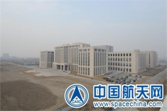
The China Academy of Space Technology (CAST) is tasked to develop new Assembly, Integration and Test Center (AITC) to support the developing of space station program (the model is shown as Fig. 1), lunar exploration program and etc. In the AITC, there is world’s largest electric shaker (1400 kN), and the Chinese largest thermal vacuum chamber and reverberation acoustic chamber. A picture on the AITC after construction is shown as Fig. 2. The Beijing Institute of spacecraft Environment Engineering (BISEE) gets the contract to design and construct these systems.
The Reverberation Acoustic Test Facility (RATF) is about 4000 m3 in volume and can achieved an empty chamber acoustic overall sound pressure level (OASPL) higher than 156 dB.
Fig. 1The model of the Chinese space station
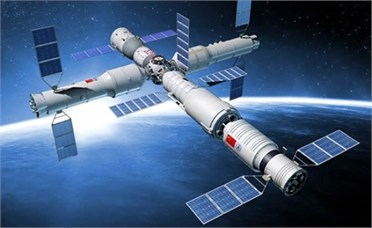
Fig. 2The new AITC of CAST
2. Specifications
The RATF’s test chamber shall physically allow a 7.5 m diameter and 18.5 m tall test specimen, and its weight is up to 30 ton.
The typical acoustic test spectrums of the existing launchers in China are shown as Fig. 3.
Fig. 3Acoustic test spectrum requirements for RATF
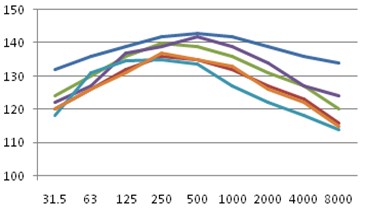
Spatial homogeneity: better than ±1 dB in the test volume.
3. Design and construction
3.1. Configuration
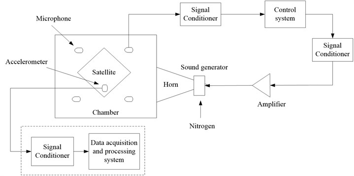
RATF usually composes of building, sound generation system, gas generation system, and control system. Fig. 4 shows the principle of acoustic test. Specimen is placed in the middle of the chamber and then the sound generation system generates high level sound pressure field. The specimen is excited and its performance in acoustic environment is verified.
Fig. 4Principle of acoustic test
3.2. Buildings
In reference with above-mentioned specification, the useful dimensions of the facility: 14.5 m (Length)×11.5 m (Width)×24 m (Height). These dimensions offer a sufficient number of modes in the low frequency domain (7 modes in the first 1/3 octave) and a useful test volume 4000 m3.
The wall and envelop is 0.7 m in thickness. Horns rooms located at the west and north sides, and the anechoic tunnel is on the top of the chamber.
A sliding door resulting in a useful 10 m×22 m entrance (the mass of the door is roughly 200 tons). The door moving on two rails, and the guiding system used for the slide door will be based on a rolling cylinder system. Fig. 5 displays the install process of the door. There is a vertical hinged man door at the sliding door.
3.3. Sound generation system
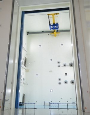
The functional specification related to acoustic performance (156 dB) has led to the noise configuration: 2 LF-60 modulators (Provided by SEREME), 6 EPT-200 modulators and 10 modulators made in China. The modulators connected to exponential horns: 20 Hz (2), 40 Hz (2), 80 Hz (2), 100 Hz (2), 160 Hz (5) and 200 Hz (7). These horns were installed in the west and north wall of the RATF, shown as Fig. 6.
Fig. 5Construction photo of the door
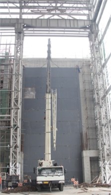
Fig. 64000 m3 acoustic chamber
3.4. Gas generation system
The sound system configuration described here-above, induces the following specification on the gas flow (gaseous nitrogen):
1) Maximum flow rate: 800 Nm3/min;
2) Gas pressure (absolute): 2.5±0.1 Bar.
In addition, the system should allow 10 acoustic runs per day at maximum flow rate, and each duration is 3 minutes. Fig. 7 shows the overall principle of the gas generation system.
Fig. 7Principle of gas generation system
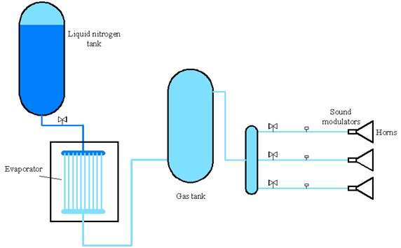
Liquid nitrogen stored in two 30 m3 tanks at 16bar. Two evaporators installed in a pool (11 m×7.5 m×4 m) filled with water.
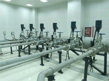
Two 30 m3 gas tanks were used to store the nitrogen gas, and reduce the fluctuation of pressure. A picture of the tanks is shown as Fig. 8.
Independent and controlled inlet is designed for each modulator by using electric valves and pressure transmitters.
Fig. 8Photo of tanks
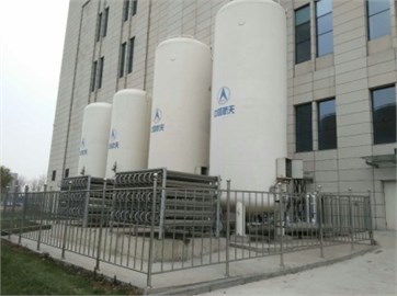
Fig. 9Pipelines and valves
3.5. Control system
Gas generation system: the control of the gas is obtained using PLC (Programmable Logic Controller), and the operator can control the pressure and flow rate at computer.
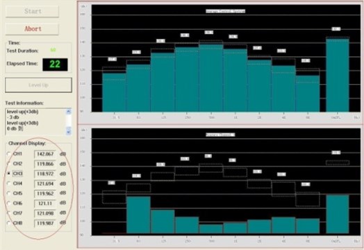
Acoustic control system: An automatic system is developed by BISEE, and it can offer a credible and efficient close loop control of acoustic test. The interface of the control software is shown as Fig. 10.
Fig. 10Interface of the acoustic control system
4. Test and use
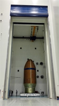
The RATF was put into use at October 2015 after acceptance tests. It was used to perform an Acoustic Fill effect test and analysis of Spacecraft, shown as Fig. 11. The result obtained enabled BISEE to define an implementation methodology and incorporate it into the ISO standard.
Fig. 11Photo taken during acoustic fill effect test
5. Conclusions
BISEE designed and constructed a new big RATF for CAST. It offers 4000 m3 useful test volume and a sufficient number of modes from the first 1/3 octave (25 Hz). The entrance is 10 m×22 m, and the OASPL is higher than 156 dB. The RATF will provide an efficient support for environment testing needs of China and world’s space program in the future.
References
-
Xiang X. H. The Test Technology of Spacecraft Mechanics Environments. China Science and Technology Press, 2010.
-
Anant Grewal High intensity noise generation for extremely large reverberant room test applications. Proceedings of the 29th IMAC, Jacksonville, USA, 2011.
-
Alain Meurat, Laurent Jezequel A new acoustic test facility at alcatel space test center. Proceedings of the 5th International Symposium on Environmental Testing for Space Programmes, Noordwijk, The Netherlands, 2004.
About this article

