Abstract
This study investigates the transmission coefficient of coupled beam structure which has been widely used in engineering problems. Although the power flow is continuous at the coupled point, the waveform and energy density often show sudden changes. These changes can be utilized to create an understanding of the system. By treating the two-beam coupled structure as two infinite beams and considering the coupling between the bending wave and the torsion one, the conversion of wave types at the coupled interface is discussed. Further, the transmission coefficient is also computed. Furthermore, investigate the effects of coupling angle, beam height and the excitation frequency of incident wave on the conversion of wave type and energy transmission. Numerical results indicate that the coupling angle and beam height have great influences on the conversion of wave type. The component of torsion wave grows with the excitation frequency and cannot be ignored in high frequencies.
1. Introduction
Beam structure has been widely used in engineering due to its convenience in arranging, disassembling and adjustment (e.g. the truss structure in spacecraft could be modeling by coupling beam structure) [1]. For the vibration analysis and acoustic prediction of those large coupled structures, the power methods which are represented by statistic power method and power flow finite element are favorable since they have many advantages over traditional methods [2].
In the statistic energy analysis (SEA) [3], the power flow is accounted for in terms of a coupling loss factor while in power balance analysis [4] the junction is described by transmission and reflection coefficients. A deterministic as opposed to a statistical approach was adopted in modeling the beam junction dynamics. Individual frame members are treated as ideal, one-dimensional structures deforming in bending, torsional, or longitudinally [5, 6]. Moore [7], Horner [8] and Langley [9] have also conducted analyses of the vibratory power transmission of general two-dimensional beam structures.
This article investigates the vibration velocities of all directions in two beams coupled structure based on the classic wave theory. According to the continuity condition at coupled interface, the amplitudes of vibration velocity of elastic wave are got. Then, the energy transmissions at the coupled interface are subsequently obtained. Finally, we discuss the influences of different coupling angle and beam height on the transmission coefficient in detail, which provides some theoretical basis for power flow analysis.
2. Transmission coefficient of coupled beam structure
There exists various coupled structure in engineering application, and most of them consist of several coupling types, such as the coupling forms at the corner of helicopter [7] shown in Fig. 1(a). Fig. 1(b) presents the typical coupled beam structure. When excitation wave incident into beam 1, the wave conversion will happen at the junction. At the same time, the reflection and transmission occur as shown in Fig. 1(b). In the following, we will discuss the conversion of wave type and calculate the transmission coefficients under excitation by the incident out-of-plane bending wave.
When computing the transmission coefficient, the finite structure can be treated as semi-infinite structure which has been discussed in Ref [10]. Since this method could provide acceptable precision, we also adopt this treatment in the present work.
Fig. 1Model of coupled structure
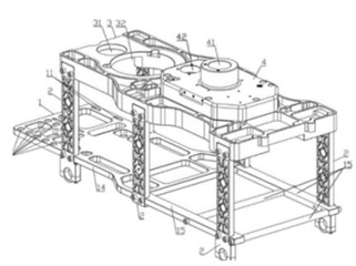
a) Helicopter frame
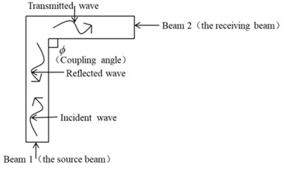
b) L-shaped coupled beams
2.1. Calculation method
When the beams lie in the same plane, the motions can be simplified into in-plane motions and out-of-plane motions and out-of-plane motion. The out-of-plane motions include bending over the lying axis and torsion. The in-plane motion includes the longitudinal deformation and bending which is perpendicular to the lying axis.
Since these two motions are uncoupled when the two beams are in the same plane, this method can handle arbitrary coupling angles. The first step is defined the global (, , ) and local (1, 2, 3) system as shown in Fig. 2.
Secondly, we should express the junction displacements in the local coordinate system. This yields the following for the translational and rotational velocities at the junction:
where and denotes the junction displacement velocities and rotational displacement velocities, respectively; can be coordinate axis. is the angle which defines the in-plane orientation of the frame with respect to the source frame.
The frame impedances relate force / moments to translational and rotational velocities in the local coordinate system:
where and denotes the force and moment, respectively, can be coordinate axis; , are the input impedances for torsion and longitudinal motion, respectively. , , are the input impedances for bending motion related translational, rotational velocity and coupled effect, respectively; , are the in plane and out-of-plane motion.
The force and moments in the global coordinate system are given in terms of the local values by:
The impedance expressions for a beam with arbitrary orientation are obtained by combining Eqs. (1)-(4). The total junction impedance in global junction coordinates is obtained by summing force and moment expressions for each frame at junction.
The mechanical power transmitting into a beam may be determined from the displacements at the junction end of the beam according to the following expression for longitudinal motion:
and for torsional wave transmission:
Bending requires a more complicated that accounts for the coupling between rotation and translation and the relative phase between these motions:
where denotes the complex conjugate.
The transmission coefficient is the ratio of transmitted to incident powers, which is obtained from Eqs. (8):
where is the incident power for a propagating wave, and are the transmitted wave and incident wave type, respectively.
Fig. 2Global and local coordinate systems
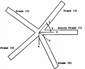
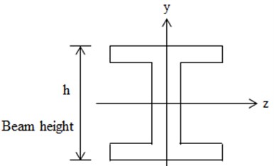
Fig. 3Beam section form
2.2. Numerical calculation
Since Aluminum alloy is widely used in aircrafts, we assume that the coupling beam consists of Aluminum. The material parameters as following: Elastic modulus 71 GPa, density 2700 kg/m3, Poisson’s ratio 0.333.
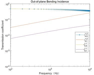
The shape of beam cross section is defined in Fig. 3, and structure parameters are given in Table 1. Here, we consider the excitation frequency between 102 Hz and 104 Hz, and the velocity of excitation wave is 1 m/s.
Fig. 4 illustrates the transmission coefficient under the excitation of out-of-plane bending wave. From this figure, we can see that the transmission coefficient changes with the excitation frequency, and the tendency is in accordance with Ref [7]. This demonstrates the present approach.
Table 1The structural parameter
Area (m2) | Length (m) | Polar moment of inertia(m4) | Moment of inertia axis (m4) | Moment of inertia axis (m4) |
3.1e-4 | 0.8 | 1.3e-7 | 2.8e-6 | 3.4e-8 |
Fig. 4Transforming of power coefficient when out-of-plane bending wave incident
3. Discussing
3.1. Effect of coupled angle on power transmission coefficient
Based on the results, we will discuss the influence of coupled angle on power transmission coefficient in this section. The coupling angle varies between 0°-180°, and the section of the beam remains the same. In the following, denotes the coefficient of power between different fields, where and could be “” (bending) and “” (torsion), and can be 1 (beam 1) and 2 (beam 2). For example, denotes the coefficient of the power from the bending wave field of beam 1 to the torsion wave field of beam 2.
When beam 1 is excited by the out-of-plane bending wave, if the coupled angle is 0°, i.e., the two beams are coincident, there are no transmissions, and all power is reflected into the bending wave field of beam 1. In this case, 1, and other coefficients are zeros. If the coupled angle is 180°, i.e., the two beams is collinear but not coincide, there are no reflections when the sections of two beams are the same. All the power transmits into the bending wave field of beam 2. Hence, 1 and other coefficients are also zeros.
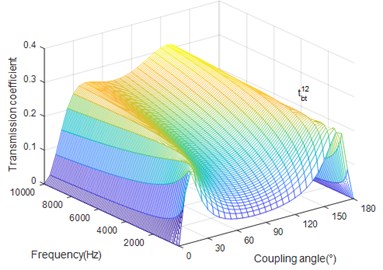
Figs. 5-8 show the influence of coupling angle and excitation frequency on the transmission coefficient of bending and torsion wave which are generated by the reflection of bending incident in beam 1 respectively.
Fig. 5 shows that the coefficient shows apparently variations and increases with the excitation frequency when the coupling angle is small. Two peak values can be observed in Fig. 6. When the coupling angle is small, the coefficient decreases as the frequency increase. While the power of torsion field increases slightly as frequency increases when the coupled angle is between the two critical angles. For big coupling angle, the coefficient decreases as frequency increases.
Fig. 7 illustrates that when coupled angle is less than critical angle, the transmission coefficient decreases as excitation frequency increase. Fig. 8 shows the fact that is between the critical angles, the transmission coefficient increases with the increase of excitation frequency. In other cases, it decreases as the frequency increase.
In summary, most of the power transmits into the bending wave field while the power of torsion wave field after wave conversion is small when the out-of-plane bending wave transmits into beam 1. When coupling angle grows, homology coefficients tend to be dominant.
Fig. 5The coupling angle (∅) influence on rbb11
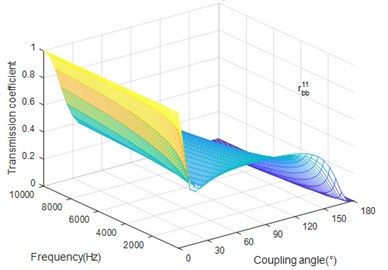
Fig. 6The coupling angle (∅) influence on rbt11
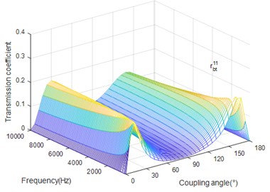
Fig. 7The coupling angle (∅) influence on tbb12
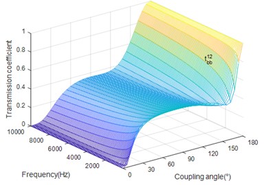
Fig. 8The coupling angle (∅) influence on tbt12
3.2. Effect of beam height
In the following section, we focus on the influence of the beam height on the transmission coefficients. Figs. 9-12 presents the coupling coefficients with different heights of the beam when coupling angle equals 90°.
Fig. 9The beam height (h) influence on rbb11
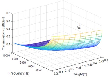
Fig. 10The beam height (h) influence on rbt11.
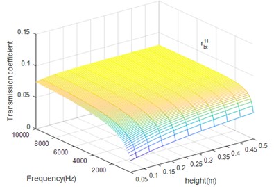
Comparing Figs. 9, 10, we can find that beam height has the opposite influence in reflection bending wave and torsion wave. When the beam height increases, the torsion reflection coefficient raise gradually, which means the conversion from bending wave to torsion wave is strengthen. Meanwhile, the max value of torsion reflection coefficient is 0.075 which is far less than bending reflection coefficient.
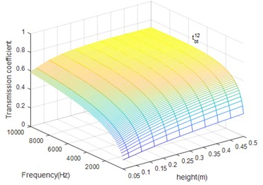
From Figs. 11 and 12 we can conclude that beam height has the opposite influence on propagation of bending and torsion wave but has the same influence on the reflection and transmission of certain wave. When the bending excitation exists in the structure, except for the bending wave, the torsion wave also has important influence in vibration, especially in high frequency case.
Fig. 11The beam height (h) influence on tbb12
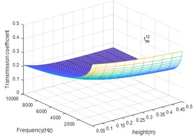
Fig. 12The beam height (h) influence on tbt12
4. Conclusions
This study analyzes the influence of the frequency of incident out-of-plane bending wave, beam height and coupling angle on the conversion of wave type and transmission coefficients are discussed in details. Some conclusions can be drawn as:
In the case of large height and high frequency, the effect of torsion wave become more heavily. Therefore, when using the power method like FEM of power flow to study the high-frequency vibration of coupled structure, wave type conversion and coupled wave fields must be concerned in computing, otherwise the result is inaccuracy even failed.
References
-
Wang Youyi, Zhao Yang, Ma Wenlai Travelling wave analysis and active control of jitter in the median and high frequency regions for coupled beam. Journal of Mechanical Engineering, Vol. 49, Issue 22, 2013, p. 188-191.
-
Song Kongjie, Zhang Wei Bo, Niu Jun-chuan Application and development of power flow theories in the field of the vibration control for flexible systems. Chinese Journal of Mechanical Engineering, Vol. 39, Issue 9, 2003, p. 23-28.
-
Lyon R. H. Statistical Energy Analysis of Dynamical Systems. MIT Press, Cambridge, MA, 1995.
-
Smith P. W. The effect of longitudinal wave coupling on the diffusion of flexural energy in a one-dimensional waveguide with lossy obstacles. The Journal of the Acoustical Society of America, Vol. 72, 1982, https://doi.org/10.1121/1.2020065.
-
Cremer L., Heckle M., Ungar E. E. Structure Borne Sound. Springer, New York, 1973.
-
Stablik M. J. Coupling loss factors at a beam L-joint revisited. The Journal of the Acoustical Society of America, Vol. 72, Issue 4, 1982, p. 1285-1288.
-
Moore J. A. Vibration transmission through frame or beam junctions. The Journal of the Acoustical Society of America, Vol. 88, Issue 6, 1982, p. 2766-2776.
-
Horner J. L. Prediction of vibration power‚ transmission in frameworks. Journal of Sound and Vibration, Vol. 10, Issue 2, 1969, p. 163-175.
-
Langley R. S., Heron K. H. Elastic wave transmission through plate/beam junctions. Journal of Sound and Vibration, Vol. 9, Issue 3, 1990, p. 469-486.
-
Cho P. E. Energy Flow Analysis of Coupled Structures. Ph.D. Thesis, Purdue University, USA, 1993.
About this article

