Abstract
Every year, many natural disasters strike Taiwan, destroying bridges and disrupting traffic. To allow shipping of relief provisions and salvage, fabricated steel bridges are often used to construct emergency relief bridges. This kind of bridge must meet strength and functionality requirements. Strength depends on the materials used, while functionality depends on displacement control. These two requirements affect the section design of the bridge deck. In order to quickly build a light-weight bridge for emergency relief with displacement control, a neutral equilibrium mechanism is proposed and developed to control the deflection of an emergency relief bridge. A neutral equilibrium mechanism is a system with an internal control mechanism that can actively change the internal structure. Structural transformation causes the size variation of the action force to respond to continuous changes in bridge deflection. This mechanism can expand the effective span of the bridge, maintain its strength and functionality, and increase the convenience of building and mobility. Experimental results reveal that a virtual pier at the center of a bridge with this proposed mechanism installed can control vertical deflection caused by vehicles carrying heavy loads. Test and analysis records also reveal that the vertical displacement at the center of a bridge with the neutral equilibrium mechanism installed is close to zero. The practicality of this neutral equilibrium mechanism has been verified by experiment.
1. Introduction
The geography of Taiwan and poor geological conditions, coupled with the steep mountains and short rivers, complicate the storage and drainage of water. In addition, Taiwan is located in the Pacific Rim seismic zone, and typhoons frequently affect the island. Further complicating the situation is that Taiwan attaches little importance to environmental conservation and hillside land reclamation, so land cannot be effectively protected. Taiwan is struck by many earthquakes of varying amplitude each year, such as the Chi-Chi earthquake of 1999, which caused massive loss of life and property, and the intensity of rainfall is increasing. These two external forces loosen mountain soil and cause debris flows, such as the double debris flow that occurred during Typhoon Morakot in 2009 [1] and Typhoon Talim in 2012 [2], introducing of Southwest airflow lead to agricultural disaster caused by heavy rainfall. Torrential rains in that typhoon caused landslides in mountain areas in southern Taiwan, resulting in heavy loss of life and property. The rapid deployment of disaster relief and post-disaster rehabilitation relies on bridges for ground transportation. Unfortunately, due to both natural and human factors, disaster-damaged bridges are impassable. Bridge construction and rehabilitation construction are both time consuming and seriously retard relief and rehabilitation work. Isolated aboriginal villages and residential areas are often cut off from emergency responses, making it difficult for persons and goods to be transported.
To quickly assemble temporary bridges for relief efforts, the Bailey Bridge [3] is always the first choice of disaster relief units in Taiwan. If the length of a Bailey bridge exceeds 35 meters, a support point must be set at the midpoint location of this bridge. However, setting a support point in a long section of a fast-moving river or stream is often difficult or impossible. Increasing the length of the bridge will inevitably lead to the following shortcomings: (1) The larger structure size increases the materials used and thus the construction cost; (2) the related assembly parts cannot be standardized; and (3) the assembly time causes delays in disaster relief.
One choice for disaster relief is to construct a light bridge. Light bridges have two primary requirements: strength and functionality. The former is related to the materials. The latter refers to the vertical displacement limit, and displacement control usually affects the design of the bridge deck section [4-7]. Both mobility and assembly convenience are very important for light bridges, so such bridges must feature a high-strength structure, simple support, and convenience of transport. A light bridge can be composed of lightweight composite materials such as Fiber Reinforced Polymer/Plastic (GFRP) [8-11], which has an elastic modulus only 1/4 to 1/6 that of steel. The deflection of a simple support bridge is two to three powers proportional to the span of this kind bridge. Therefore, because GFRP is not conducive to deflection, the span of a light bridge is restricted by the material. The deflection of this bridge can be passively controlled by different structures to increase the bridge span, but such designs also impose limitations on relief efforts. The other choice for disaster relief is to apply active control techniques [12, 13] for emergency bridge. But, the equipment of active control is too heavy and hard to transport and install at the disaster location.
In this article, a neutral equilibrium mechanism (NEM) is proposed to control the deflection of a bridge and easy carriage. An NEM is a system with an internal control mechanism that can actively change the internal structure of the bridge. The size of the control force can be transformed to respond to variations in the deflection of a continuous structure supporting a vehicle load. The valid span of a bridge can be increased by this proposed NEM to maintain the strength and functionality of the bridge. The convenience and flexibility can thus be improved. This proposed NEM is unlimited by the traditional structural control methods for bridges, and the control of the deflection of the bridge is unrestricted by the material selection and section design. To investigate the feasibility and practicality of this proposed NEM, a reduced-scale structural model of the bridge was tested to verify the deflection variations of the bridge under the load of a dynamic vehicle.
2. Concept of virtual piers of this mechanism
2.1. Concept of neutral equilibrium mechanism
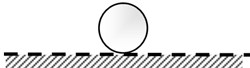
Fig. 1 shows the balanced state of a structure, which can be divided into three states: stable balance, neutral balance, and unstable balance. Fig. 1(a) shows that a rigid sphere moves from the equilibrium position to other positions due to a disturbance force. But when the disturbance force is removed, this rigid sphere returns to the equilibrium position, which is the state of “Stable Equilibrium”. Fig. 1(b) is another form of balance. A rigid sphere will not change the former movement state after the disturbance force is removed, a state called “neutral-balance” or “Neutral Equilibrium”. Fig. 1(c) shows that if a rigid ball deviates from the equilibrium position and the disturbance force is removed, it will not return to its original position. Instead, it will roll farther; this situation is “Unstable Equilibrium”. The potential energy of a rigid sphere reaches its highest point in the unstable equilibrium state. Thus, when a rigid sphere deviates from the equilibrium position, its potential energy decreases. When the potential energy of the body decreases, its kinetic energy will be enhanced. If this energy can be appropriately used to produce a useful active control force, it may allow the design of a labor-saving tool. An unstable equilibrium system (Fig. 1(c)) and a stable balance system (Fig. 1(a)) in series could create a neutral equilibrium system (Fig. 1(b)). Such a system would cause no damage to the structure due to the unstable state of the structure, and it would also apply an arbitrary control force to the structure.
Fig. 1Rigid body equilibrium status
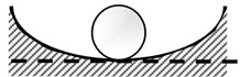
a) Stable equilibrium
b) Neutral equilibrium
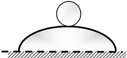
c) Unstable equilibrium
2.2. Composition of neutral equilibrium mechanism
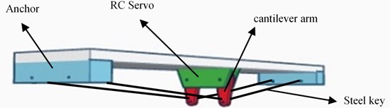
The solid structure of the NEM, shown in Fig. 2, is composed of a servo motor, a cantilever arm, steel keys, and an anchor. The main functions of these components are as follows. The servo motor controls the rotation of the cantilever arm; the cantilever arm controls the distance between the fixed steel keys and the anchor line distances for the length of the arm; the steel keys provide the control force for the NEM and steel keys with prestressed force; the anchor fixes the steel keys in position.
Fig. 2Sketch of this proposed neutral equilibrium mechanism
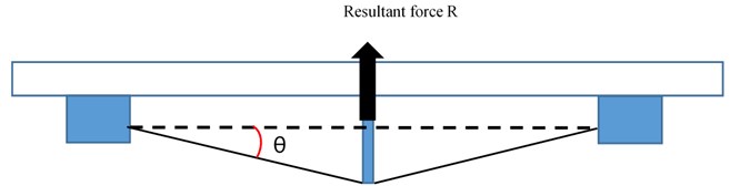
2.3. The operation principle of the NEM
The NEM is installed on the underside of the bridge, and it is erected with two steel keys below it. A rotating mechanism is also set at the middle point of the steel keys on the underside of the bridge. These steel keys are expanded outward by rotation of the cantilever arms such that the steel keys and the anchor line produce an angle . The force balance in Fig. 3 shows that the prestressed steel keys on the cantilever arms produce a resultant force . The direction of this resultant force is perpendicular to the underside of the bridge and upward. The cantilever arms act as a virtual pier to offer the bridge an upward support force. Assuming the prestressed steel keys are , the span of the bridge is , and the length of the cantilever arms is , the angle of the steel anchor and key can be obtained as follows:
Then the resultant force can be obtained from as follows:
Fig. 3Side view of NEM and resultant force R
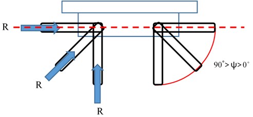
When the cantilever arms are perpendicular to the bridge deck, the maximum control force can be achieved, equal to the resultant force . The cantilever arms can be rotated by the servo motor. The rotation angle of the cantilever arms varies from horizontal to vertical to the bridge deck, as shown in Fig. 4. The horizontal component and vertical force can be adjusted through the rotation angles of the cantilever arms to change the direction of the force on the cantilever arms. is the angle between the cantilever arms and the bridge deck. The vertical component of the resultant force is the size of the control force. The force direction is upward, which causes upward displacement to offset the downward displacement caused by the vehicle load. The horizontal component of the resultant force can be neutralized by the opposite directions of two symmetric horizontal components of the cantilever arms. The control force can be obtained by :
The angle can be obtained from the output signal of the servo motor; thus, can be found with the following equation:
Fig. 4Front view of NEM and angle variation
In operation, the NEM uses sensors such as a displacement meter and speedometer to detect the displacement of the bridge. The sensor data are imported into the micro-computer controller to calculate the size of the required control force and then to obtain the rotation angle of the cantilever arms. This angle is output to the servo motor, which then drives the rotation to the specified angle. In an ideal situation, the midpoint of the bridge undergoes no displacement. The length of the steel keys remains unchanged, so the resultant force of the cantilever arms remains unchanged. In short, the internal energy neither increases nor decreases. Theoretically, the NEM does not need energy to turn the cantilever arms, but the shafts of the cantilever arms need to be connected with the anchor points in a line. To attain Neutral equilibrium, the resultant force of the cantilever arms cannot be changed because of the rotation of the cantilever arms. The size transformation of the control force is accompanied by changes in the physical quantity of the bridge in the actual operation of the NEM. Therefore, in the ideal situation, no displacement of the bridge occurs. The steel key length will change within the system of energy changes. The rotation of the cantilever arms requires enough torque and strength to overcome the internal energy change.
3. Experimental set-up
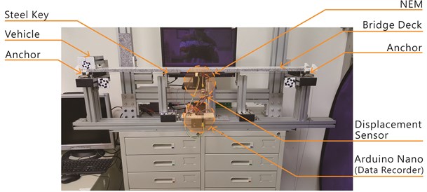
The experimental set-up is presented in Fig. 5. The control mechanisms presented in this article for testing are as follows: (1) a digital server has torque of 250 N·cm; (2) the material of the cantilever arm is Polylactic acid (PLA), and fixed tendons and anchor points are arranged in the cantilever arm; (3) the tensile strength of the PE line is 250 N; (4) in the bridge model, the material of the bridge deck plate is Polypropylene plastic (PP). Young's modulus is between 1,300 and 1,800 (N/mm2). The moment of inertia of the bridge section is3.38×105 (mm4). The length of the reduced scale of bridge is 1,100 mm, the width is 120 mm, and the thickness is 15 mm. The anchor chock is made of aluminum and has a length of 120 mm, width of 30 mm, and thickness of 20 mm. The bridge model is simple supported. The resistive type of displacement meter is used in this research to measure the displacement variation at the midpoint of the bridge model. Displacement of the bridge pushes brushes at the same time to change the output voltage, and the change in voltage is used to calculate the displacement of the bridge. Speed responses are sent to the single-chip controller, which uses the detected displacement and time intervals of sensor data to calculate the speed. As the driving source of the cantilever, Radio Control servos (RC servos) are used to simulate the functionality of the servo motor. RC servos are commonly used in the RC models, which is equipped with built-in angle control. The accuracy if the RC servo reaches to 0.083 degrees. An Arduino Nano V3 micro-computer controller is adopted in this research to control the entire operation of this proposed mechanism, including calculation, linking, and the transmission of data to the RC servo and displacement meter. The operation principle of the NEM is to receive the displacement variation of the bridge at the midpoint of the bridge and calculate a speed instantaneously. Then the required control force is calculated to predict the rotation angle of the RC servo to turn the RC servo.
Fig. 5Experimental set-up of reduced-scale bridge for NEM
4. Results and discussion
The purpose of this experiment was to test and verify the feasibility of application of the neutral equilibrium mechanism control approach at the midpoint of a bridge to form a virtual pier, and also to validate and assess the control effect of this proposed NEM to control the deformation of the bridge with a moving load.
4.1. Experimental parameters
The main power source was applied to the Servo machine, with very small output power for the remote control model to investigate and compare the deformation control effects of the displacement response of the bridge under static load, low-speed dynamic vehicle load, and high-speed vehicle load. The test parameters of the moving load speed in this research were divided into the following sets:
Static Test: The weight of the tackle was 18.97 N, placed at the endpoints, 0.1 L, 0.2 L, …, 1.0 L (the other endpoint) to measure the displacement of the bridge. Assuming the real length of this test bridge is 20 m.
Low-Speed dynamic test: The weight of the tackle was 18.97 N with 6.4 cm/sec speed across the bridge. The passing time was 16 seconds to simulate a vehicle speed of 4.5 km/hr.
High-speed dynamic test: The weight of the tackle was 18.97 N with 22.7 cm/sec speed across the bridge. The passing time was 4.5 seconds to simulate a vehicle speed of 16 km/hr.
4.2. Test results
4.2.1. Comparison of static tests
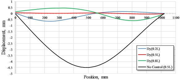
Test results of static tests of the model bridge with and without NEM control are shown in Fig. 6. The black line, blue line, and red line of Fig. 6 reveal the deformation curve of the bridge without control with the load placed at midpoint, with NEM control with the load placed at 1/5 L, and with NEM control with the load placed at 4/5 L, respectively. The maximum deformation of the bridge under NEM control is 0.65 mm, which is obviously lower than that of the bridge without control, and the maximum displacement is 4.54 mm. Notably, when the load is placed at the midpoint of the bridge, almost no deformation occurs in the bridge with NEM control because the control force and load offset each other. Otherwise, a slight upward displacement of the bridge occurs when the load is placed at 4/5 L to the left of the bearing. This simulates the absence of down pressure on the left side of the bearing. In contrast, on the right side of the bearing, this phenomenon does not occur because downward pressure is exerted to resist the lifting force. Therefore, when the weight of the bridge is smaller, the lifting force occurs at the endpoints of the bridge. Precautionary measures must be designed to prevent this phenomenon.
Fig. 6The deformation curves of static test of bridge without control and with NEM control
4.2.2. Comparison of dynamic tests with low speed
Fig. 7 shows that the maximum displacement of the bridge without control (black line) reaches 4.95 mm, equivalent to near 1/200 of the span, or greater than 1/500 of the span. This is not within the deformation limit of an emergency bridge. The red line, for the bridge with NEM control, displays the time history of displacement at the midpoint of the bridge, which is obviously lower than those of the bridge without control. Notably, the maximum deformation of the bridge under NEM control is 0.17 mm (upward), which is lower than 1/6,000 of the net span and fully compatible with the design criteria of a bridge. The variation of the rotation angle of the cantilever arm reveals that the rotation angle increases along with the moving load to the midpoint to produce a larger upward force to offset the action force of the tackle. Fig. 6 also shows that the displacement control results achieve a constructive effect with the common angle control accuracy of the RC servo. These results demonstrate the robustness of this proposed NEM.
4.2.3. Comparison of dynamic tests with high speed
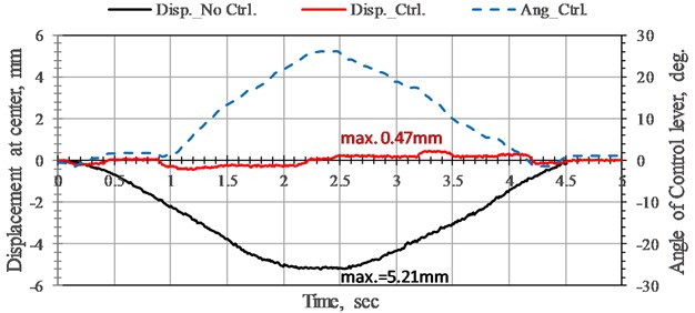
Fig. 8 shows the maximum displacement of the bridge without control (black line), with control (red line), and control angle variation (blue line). No matter what the control conditions are, the displacement variations are relatively large at the midpoint of the bridge. Because the ratio of the moving speed of the tackle and the multiplication of span of the bridge, and natural frequency of the bridge is still very small. Therefore, the displacement change of the bridge without control is small. But when the deformation of the bridge is controlled by the NEM, the displacement of 0.47 mm downward at the midpoint is approximately double those under the load of low speed tackle. This displacement is still less than 1/2,000 of the span, which is far less than the 1/500 required by the design criteria. Therefore, this proposed NEM can effectively reduce the deformation of the bridge even when the bridge is under a load of high-speed tackle. The NEM can increase the effective span of the bridge to increase the flexibility of an emergency relief bridge without increasing the cross-section of the bridge.
Fig. 7Time history of displacement responses and rotation angle variation of bridge without control and with NEM control at the midpoint of bridge under low-speed tackle. Moving load speed 6.38 cm/sec
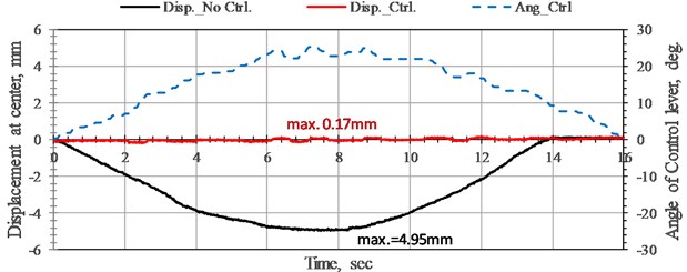
Fig. 8Time history of displacement responses and rotation angle variation of bridge without control and with NEM control at the midpoint of bridge under high-speed tackle. Moving load speed 22.7 cm/sec
5. Conclusions
For rapid assembly of a temporary bridge for relief without limitation of the length of the span, a neutral equilibrium mechanism is proposed to form a virtual pier to control the deformation of the bridge deck at the midpoint of the bridge. The proposed NEM consists of a RC servo, cantilever arm, steel keys, and anchor. A static test and tests under dynamic load at low and high speeds were conducted to verify the robustness and flexibility of this proposed NEM. The conclusions from a series of laboratory test results are summarized as follows:
1) In the static test, the maximum displacement of the bridge with NEM control was only 14.32 % of that without control.
2) This proposed NEM control method can reduce effectively the maximum displacement of the bridge to meet the design requirements for bridges with loads of moving vehicles at both low and high speed.
3) The rotation angle of the cantilever arm increases along with the moving load to produce a lifting force that cancels out the action force of the vehicle and forms a virtual pier to support the bridge deck.
These test results demonstrate that this proposed NEM can form a virtual pier to increase the effective span of a bridge without increasing the cross-section of the bridge. The practicability and effectiveness of this proposed NEM control method have been verified in this research. Future studies will further research compound control methods featuring multiple virtual piers, combined with open-loop and closed-loop control, to obtain the optimal design parameters and displacement control effects of this NEM.
References
-
Typhoon Morakot, https://en.wikipedia.org/wiki/Typhoon_Morakot.
-
Typhoon Talim, https://en.wikipedia.org/wiki/Typhoon_Talim.
-
UK Military Bridging – Equipment (The Bailey Bridge), http://www.thinkdefence.co.uk/2012/01/uk-military-bridging-equipment-the-bailey-bridge/.
-
Design Criteria for Bridges and Other Structures, Transport and Main Roads. Department of Transportation and Main Roads, Australia, 2017.
-
Bridge Design Manual. Colorado State Department of Transportation, USA, 2012.
-
Bridge Design Criteria. American Association of State Highway and Transportation Officials, 2016.
-
Bridge Design Manual LRFD. Washington State Department of Transportation, USA, 2016.
-
Lee J., Kim Y., Jung J., Kosmatka J. Experimental characterization of a pultruded GFRP bridge deck for light-weight vehicles. Composite Structures, Vol. 80, Issue 1, 2007, p. 141-151.
-
Feng P. All FRP and FRP-concrete hybrid components for bridges: experiments, theories and case study. The Third Asia-Pacific Conference on FRP in Structures, 2012.
-
Mieres J. M., Calvo I., Miravete A., Gutiérrez E., Shahidi E., López C., Cuartero J., Comino P., Guzmán de Villoria Y. R. Description of a traffic bridge of the Cantabrian Speed Way made of composite materials. Materiales de Construcción, Vol. 56, Issue 284, 2006, p. 81-86.
-
Stankiewicz B. Bridge structures with GFRP composite deck. Open Journal of Civil Engineering, Vol. 5, Issue 01, 2015, p. 54236.
-
Preumont A., Seto K. Active Control of Structures. Wiley, 2008.
-
Yu W., Thenozhi S. Active Structural Control with Stable Fuzzy PID Techniques. Chapter 2, Springer, 2016.
Cited by
About this article

The authors would like to acknowledge the support of Taiwan Ministry of Science and Technology through grant No. MOST-105-2221-E-260-003 and MOST-105-2221-M-167-001.
