Abstract
In order to improve the vibratory roller’s ride comfort, a 3-D nonlinear dynamic model of the vehicle interacting with the off-road terrain is established. A damper hydraulic mount is studied and combined with the cab’s rubber mounts to simulate and evaluate the performance of the ride comfort. The weighted RMS acceleration responses of the vertical driver’s seat, the cab’s pitch and roll angle are chosen as objective functions. The results show that the cab’s rubber mounts combined with the damper hydraulic mount are clearly improved the ride comfort under various operating conditions. Especially, with damping coefficients 1.8 kN.s.m-1, the weighted RMS values of the vertical driver’s seat, the cab’s pitch and roll angle are greatly reduced by 27.8 %, 22.7 % and 64.3 % in condition of the vehicle traveling, and by 23.8 %, 20.0 % and 63.7 % in condition of the vehicle compacting on an elastic-plastic terrain.
Highlights
- Vibratory roller, cab's isolation mounts, ride comfort
- Vehicle dynamic model
- Off-road terrain, deformable terrain
1. Introduction
The off-road vibratory roller is a compactor which often uses in the field of the construction site, factories, etc. Its operating principle is the combination of the static force of the vehicle and the dynamic force of the drum to compact soil ground, asphalt and other materials. Thus, designers always want the excitation force of the drum to achieve the maximum value, whereas vibrations are transmitted from the drum/tires through the vibration isolation systems into the cab floor and the driver’s seat to achieve the minimum value. Almost the vibratory roller is not equipped with the suspension system to link between the chassis and the axles, so the vibration sources impact to the driver via the cab’s isolation system and driver’s seat suspension. Thus, the cab’s isolation system is one of the most important factors to improve the vehicle ride comfort.
Basic researches of the tire-deformable soil interaction [1-3], of the rigid drum and elastic-plastic soil interaction [4] indicated that the vibration responses of the vehicle are greatly influenced by off-road terrain. Almost the vehicle cab is always equipped with the rubber mounts with high stiffness characteristic and low damping of rubber material [5-7]. Therefore, the stiff rubber property helps suppress only high-frequency vibration and noise, contrariwise, the low damping of the natural rubber generates the high magnitude vibrations which can reduce the vehicle’s ride comfort [6]. The influence of design parameters of the cab’s rubber mounts on the ride comfort was analyzed [5], the parameters of the cab’s rubber mounts were then optimized to increase the ride comfort [7]. The results showed that the vehicle’s ride comfort was improved. However, the vibrations of the vertical driver’s seat and the cab’s pitch angle are still great under operation conditions.
In order to improve the driver’s ride comfort and controlling the cab shaking of the vehicle. A dynamic model of the vibratory roller is established based on the elastic-plastic soil model [4] and the hypothesis of the soft soil model [1]. The cab’s rubber system is then added by the damper hydraulic mounts to analyze the performance of the ride comfort. The vibration excitations consist of the interactions of the drum/tires-terrain roughness surface when the vehicle travels on a soft soil and an excitation frequency 28 Hz of the drum when the vehicle compacts on the elastic-plastic soil. The performance of the ride comfort is evaluated through the weighted root-mean-square (RMS) acceleration responses of the vertical driver’s seat (), the cab’s pitch () and roll () angle under operation conditions.
2. Off-road vehicle model
2.1. Vibratory roller dynamic model
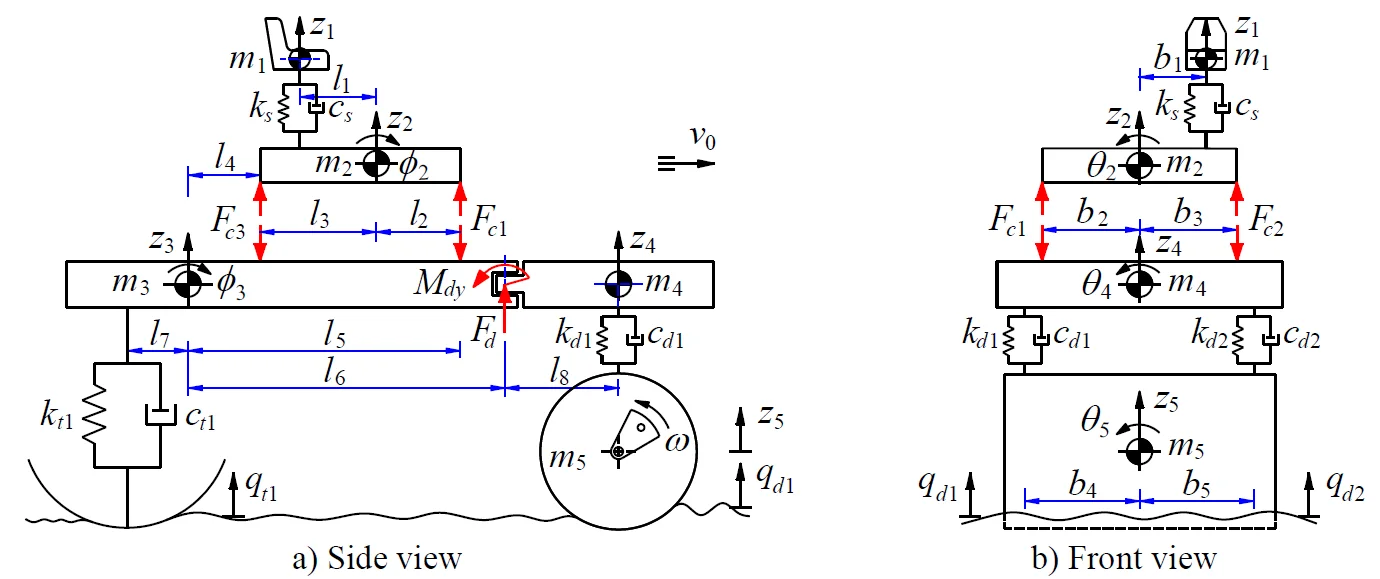
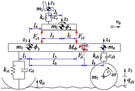
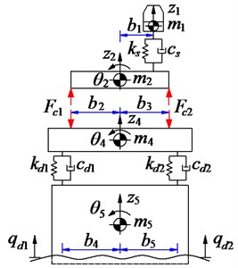
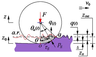
A 3-D nonlinear dynamic model of an off-road vibratory roller with 9 degrees of freedom (DOF) considering the interaction between wheels and off-road terrains is established to analyze the performance of cab’s isolation system, as shown in Fig. 1.
In Fig. 1, and are the vertical displacements and masses at centre of gravity of the driver’s seat, the cab, the rear/front vehicle frame and the drum; and are the angular displacements at centre of gravity of the cab, the rear/front vehicle frame and the drum; , , and , , are the stiffness and damping coefficients of the driver’s seat suspension, the drum’s rubber mounts and tires; are the dynamic reaction forces of the cab’s isolation mounts; and are the excitations of the off-road terrains; and is the distances of the vehicle ( 1-4; 2-5; 1-8; 1-5).
Based on the vehicle dynamic model in Fig. 1, and by applying Newton’s second law of motion, the motion equations of the vehicle can be represented in the matrix form as follows:
where [], [] and [] are (×) mass, damping and stiffness matrices, respectively, {} is the (×1) displacement vector, {} is the (×1) exciting force vector, and is the number of DOF., ( 9).
Fig. 13D dynamic model of an off-road vibratory roller with cab’s isolation system
a) Side view
b) Front view
2.2. Cab’s vibration isolation system model
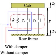
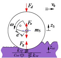
The lumped parameter model of the cab’s isolation system is described as in Fig. 2(a). Herein, and are the linear stiffness and damping coefficient of the rubber mount, is the damping coefficient of the hydraulic mount which is added in the cab’s isolation system.
The corresponding dynamic force of the mount of the cab’s isolation mounts is given by:
where (, ) and (, ) are the relative velocities and the displacements of the cab floor and the rear vehicle frame at the mount and there are given by:
where 1, 2 then 1, 5 and 1, and 3, 4 then 2, 4 and 1.
Fig. 2The exciting forces models of cab’s isolation system, the tires and the drum
a) Cab’s isolation system
b) Wheel-deformable soil interaction
c) Drum and elastic-plastic interaction
2.3. Dynamic off-road vehicle and deformable soil interaction models
2.3.1. The wheels-deformable soil contact model
The vibratory roller travels on the deformable terrain into the workshop, the drum/tires-deformable soil contact model with the terrain roughness surface is investigated based on the traditional model of Bakker and Wong [1, 2]. The wheel moves on a random terrain surface of deformable terrain, under the effect of the static and dynamic loads of the wheel, the terrain is then sunk , as seen in Fig. 2(b). The pressure and the shear stress arising from the soil compression in the deformable area region (arc of ) thus impact contrary on the wheel. Consequently, the reaction force of the soil under the wheel is given by:
The and were given by Bakker [1] as follows:
Assuming .. is the average roughness line of the terrain surface, thus, the sinking of the soil can be determined by , herein, is the random excitation of the off-road terrain surface and it is described as follows:
The ride comfort of the vibratory roller is strongly influenced not only by wheels-deformable terrain interaction but also by the rough terrain surfaces . Therefore, the spectral density of the off-road terrain surface is written in accordance with the ISO proposal [8] over the different spatial frequency ranges by . Herein, 3 for and 2.25 for , the value provides a measure for the random terrain with the reference spatial frequency 1/2 (cycle.m-1).
More specifically, assuming the vehicle travels with a constant speed , the off-road terrain irregularities can be simulated by the series:
where is the number of intervals, is the amplitude of each the excitation harmonic in which S is the target spectral density, and is the length of the road segment, is a random phase uniformly distributed between 0 and 2, and is the fundamental temporal frequency. Mitschke [3] extended the spectral density ranges for the unpaved off-road classifications apart from the traditional asphalt road classifications, including the classification ranges from good to very poor, and the desired terrain roughness can be yielded by choosing a value in the spectral density ranges.
According to the dynamic model of the vibratory roller in Fig. 1 and the wheels-soft terrain interaction model in Fig. 2(b), the excitation forces and of the wheels and the drum from the deformable terrain to the rear/front vehicle frame are described by Eq. (8) and Eq. (9):
2.3.2. The rigid drum and elastic-plastic soil interaction model
The vibratory roller uses the most of its time to work on the workshop which often operates under the elastic-plastic soil. Therefore, according to Adam and Kop [4], a model of the rigid drum and elastic-plastic soil contact is established in Fig. 2(c), the elastic-plastic property can be expressed by a plasticity factor and a soil damping to plasticity ratio as following:
where is the compression ratio, is the elastic stiffness, is the compression stiffness, is the compression damper.
In an exciting vibration cycle of the drum-deformed soil contact, the motion of the vibratory drum on a soil patch of given density may exhibit, over each cycle of the vibratory drum, two or more often three distinct phases, which are described as follows: (1) Loading Phase: The gravel-soil ground is compressed by the drum, thus, the gravel-soil ground density is increased and it has become elasticity. The elastic stiffness and compression stiffness of the gravel-soil ground are increased while the compression damper is decreased. In order to describe the relation of , and , the vibration equation of the drum is given by Eq. (11) [5]; (2) Unloading Phase: The roller drum moves upward, the gravel-soil ground is restored. The vibration equation of the drum is written by Eq. (12); and (3) Drum-Hope Phase: The gravel-soil ground has become elasticity, the drum is easy to separate from the soil ground surface, and the vibration equation is also written by Eq. (13):
From Eqs. (11)-(13), the motion of the drum and the excitation forces is then determined.
3. Results and discussion
3.1. The off-road vehicle travels to the workshop
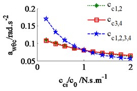
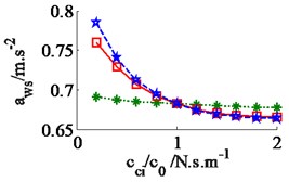
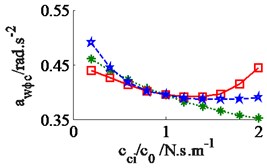
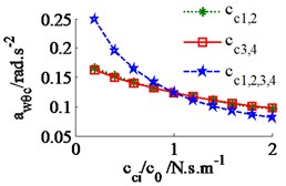
The effect of the damping coefficients to the vehicle ride comfort is evaluated through the evaluate indices of the weighted RMS acceleration responses () in ISO 2631-1 (1997) [9]. In a condition of the vehicle traveling into the workshop, the reference parameters of a vibratory roller [6] and a Grenville SAND deformation with its poor off-road classification [3] are used to simulate at a vehicle velocity of 2.22 m.s-1 (8 km.h-1). Assuming the initial damping coefficients of the damper hydraulic mounts are 1.5 kN.s.m-1. The damping coefficients with three different cases of the mount are simulated, as seen in Fig. 4. The results show that the weighted RMS acceleration responses of the driver’s seat (), the cab’s pitch and roll angle ( and ) are lightly affected by the damping coefficients of the front-end mounts, whereas these values are strongly affected by the damping coefficients of the rear-end mounts and of all mounts . However, the effect of all to the ride comfort is insignificant in comparison with of rear-end mounts, therefore, the values are chosen to analyze the results. Fig. 4(a), (b) and (c) show that all values of and are strongly reduced; both values of and are greatly reduced, especially , however, the value of is enhanced. It implies that the comfortable shake of the driver is enhanced while the vertical driver’s ride comfort is decreased. The minimum value of is obtained in a range of (see Fig. 4(a)). In order to improve the ride comfort in all directions, the values of could be chosen in a range of . With the values of is chosen by 1.8 kN.s.m-1 and 1.5 kN.s.m-1, the simulation results is plotted in Fig. 5. The results show that the acceleration responses of the driver’s seat, the cab’s pitch and roll angle are significantly reduced in comparison with the cab’s isolation system without the damper hydraulic mounts. The weighted RMS values of , and in Table 1 are clearly decreased by 27.8 %, 22.7 % and 64.3 % in comparison with the cab’s isolation system without the damper hydraulic mounts.
Fig. 4Effect of the damper coefficients to the ride comfort on a deformable soil ground
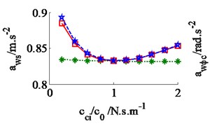
a) The vertical driver’s seat
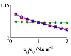
b) The cab’s pitch angle
c) The cab’s roll angle
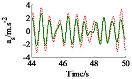
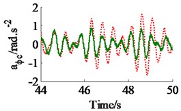
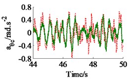
Fig. 5The acceleration responses of the driver’s seat and the cab on a deformable soil ground
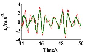
a) The vertical driver’s seat
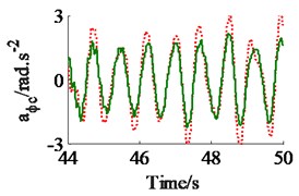
b) The cab’s pitch angle
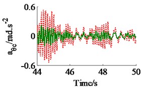
c) The cab’s roll angle

Table 1Weighted RMS values of the driver’s seat and cab on a deformable soil ground
Parameters | m.s-2 | rad.s-2 | rad.s-2 |
Without damper | 1.15 | 1.36 | 0.202 |
With damper | 0.83 | 1.05 | 0.072 |
Reduction (%) | 27.8 % | 22.7 % | 64.3 % |
Table 2Weighted RMS values of the driver’s seat and cab on an elastic-plastic soil ground
Parameters | m.s-2 | rad.s-2 | rad.s-2 |
Without damper | 0.88 | 0.50 | 0.323 |
With damper | 0.67 | 0.40 | 0.117 |
Reduction (%) | 23.8 % | 20.0 % | 63.7 % |
3.2. The off-road vehicle works in the workshop
In a condition of the vehicle working in the workshop, a low-density soil of elastic-plastic soil [4] with a vehicle velocity of 1.38 m.s-1 (5 km.h-1) and under an exciting frequency, 28 Hz, of the drum are chosen to analyze the ride comfort. It is also assumed that the initial damping coefficients of the damper hydraulic mounts are 1.5 kN.s.m-1. The simulation results in Fig. 6 show that the effect of the damping coefficients in cases of , , and is also similar in a condition of the vehicle traveling. Thus, the values cc3,4 are also chosen to analyze the results. Fig. 6(a) and (c) show that , both the value of and are clearly decreased; Fig. 6(b) shows that , the value is also reduced, however, , the value is significantly enhanced. Therefore, in order to improve the ride comfort in all directions, the values of could be chosen in a range of With the values of is also chosen by 1.8 kN.s.m-1 and 1.5 kN.s.m-1, the simulation results is seen in Fig. 7. The results show that the acceleration responses are significantly reduced in comparison with the cab’s rubber mounts. The weighted RMS values of , and in Table 2 are also reduced by 23.8 %, 20.0 % and 63.7 % in comparison with the cab’s isolation system without the damper hydraulic mounts.
Fig. 6Effect of the damper coefficients to the ride comfort on an elastic-plastic soil ground
a) The vertical driver’s seat
b) The cab’s pitch angle
c) The cab’s roll angle
Fig. 7The acceleration responses of the driver’s seat and cab on an elastic-plastic soil ground
a) The vertical driver’s seat
b) The cab’s pitch angle
c) The cab’s roll angle

4. Conclusions
The ride comfort performance of the off-road vibratory roller cab’s isolation system added the damper hydraulic mount is clearly improved under operating conditions. Especially, (1) In a condition of the vehicle traveling, with 1.5 kN.s.m-1 and 1.8 kN.s.m-1, the weighted RMS values of , and are significantly reduced by 27.8 %, 22.7 % and 64.3 % in comparison with the cab’s isolation system without the damper hydraulic mounts. (2) In a condition of the vehicle compacting, with 1.5 kN.s.m-1 and 1.8 kN.s.m-1, the weighted RMS values of , and are significantly reduced by 23.8 %, 20.0 % and 63.7 % in comparison with the cab’s isolation system without the damper hydraulic mounts.
References
-
Bekker M. Introduction to Terrain-Vehicle Systems. University of Michigan Press, Ann Arbor, 1969.
-
Wong J. Theory of Ground Vehicles. John Wiley and Sons Inc, New York, 2001.
-
Mitschke M. Dynamik Der Kraftfahrzeuge. Springer-Verlag, Berlin, 1972.
-
Adam D., Kopf F. Theoretical analysis of dynamically loaded soils. European Workshop Compaction of Soils and Granular Materials, Paris, 2000, p. 207-220.
-
Kordestani A., Rakheja S., Marcotte P., Pazooki A., Juras D. Analysis of ride vibration environment of soil compactors. International Journal of Commercial Vehicles, Vol. 3, Issue 1, 2010, p. 259-272.
-
Van Liem N., Jianrun Z., et al. Vibration analysis and modeling of an off-road vibratory roller equipped with three different cab’s isolation mounts. Shock and Vibration, Vol. 2018, 2018, p. 1-12.
-
Le V. Q., Nguyen K. T. Optimal design parameters of cab’s isolation system for vibratory roller using a multi-objective genetic algorithm. Applied Mechanics and Materials, Vol. 875, 2017, p. 105-112.
-
SO/TC108/SC2/WG4 N57, Reporting Vehicle Road Surface Irregularities, 1982.
-
ISO 2631-1. Mechanical Vibration and Shock-Evaluation of Human Exposure to Whole Body Vibration-Part 1: General Requirements, 1997.
Cited by
About this article

