Abstract
Three-point bending test is conducted by help of Finite Element Method to find out mechanical properties of Inconel 718 coating on stainless steel. For doing this ANSYS package are employed to visualise exact situation of bending test so that can find out stress field developed during the test. A 3D modelling of coating and substrate material is used. Load versus displacement relationships is compared with reference results. It is noticed that yield stress of substrate material is higher than the tensile stress of substrate and coating. Due to this reason there is initiation of crack at coating-substrate interface and it is propagated which leads to failure with applied load.
1. Introduction
With the advancement in technology materials of high performance are required now a days to meet technological challenges in field of surface coating. Coatings are applied at materials to reduce friction and so the wear. A good coating applied have some characteristics as it should have resistance to wear and mechanical forces in operating conditions. The mechanical properties of coating as well as coating-substrate interface is vital for good coatings and therefore its study becomes crucial. Three-point bending test is a promising method to find out mechanical properties of coating-substrate material. It is a classical method to find out stress field and young’s modulus in shape of metal sheet of given length which rests on two supports and subjected to applied load at centre.
A considerable research work has been done to examine mechanical properties of coatings by three-point bending tests. Three-point bending test of High Velocity Oxygen Fuel Inconel 625 Coatings on mild steel substrate are investigated by experimental and FEM simulation by Arif et al. [1]. They showed that yield stress of sheet metal is higher than the tensile stress of substrate and coating. Three-point bending test of High Velocity Oxygen Fuel AMDRY 9954 coatings on Ti-6Al-4V alloy substrate are examined by Anazi et al. [2]. They reported that cracks are formed in coatings in deformed region which results in partial delamination of coatings from substrate material which is due to stress relaxation of coating-substrate material during bend test of workpiece. Three-point bend testings of High Velocity Oxygen Fuel Inconel 625 coatings on mild steel substrate and its Nd: YAG laser treating sample observed by Yilbis et al. [3]. They show that after the laser treatment elastic limit of coating reduces and origin of the crack sites are the imperfection sites of coating-substrate material interface. Three-points bending tests to find out the mechanical behaviour of thermal barrier coatings are examined by Planques et al. [4]. They discussed that because of delamination of coatings cracks are produced which enlarges smoothly and it is increases with bending. Mechanical property of nickel-based alloy (NiCrMoAlFe) coating is investigated by Hidalgo et al. [5]. They performed tensile test to find out thermal fatigue and the adhesion between the coating-substrate interface. They showed that there is a good adhesion between substrate-coating interface and it is not affected by thermal fatigue. Three-point bending test of the bolt reinforcement of a composite-to-steel butt-joint is studied by Kharghania et al. [6] They mentioned that the FEM models is promising tool to predict the failure location as well as structural response of the joint up to the loading at which debonding initiates. Three-point bend testing on zinc coating on 304 stainless steel substrates were carried out with different film thicknesses by Zhang et al. [7]. They showed that the interface crack propagation length increases with increase of film thickness and by increasing external load. The stress phase angle at the tip of crack decreases by increase of Young’s modulus of the coating. Three-point bending test performed on brittle coating and substrate structures for crack growth by FEM simulation by Ghasemi et al. [8]. They showed that when the fracture energy in coating and substrate are in the same range, cracks created in the coating were transferred to the substrate.
In the present study, coating of Inconel 718 (C 0.08 % Mn 0.35 % Si 0.35 % Ti 0.6% Al 0.8 % Co 1 % Mb 3 % Cb 5 % Cr 19.0 % Fe 17 % Ni 52.82 %) powders on Stainless Steel is used. Mechanical properties of coating-substrate interface are studied by three-point bend testing at room temperature. The bend testing models (geometry and supports etc.) and its environmental conditions (load and displacement etc.) are created and simulated using the ANSYS package which is a finite element method. Stress field in the coating material and coating-substrate interface is calculated numerical method.
Table 1Material property employed for finite element methods
Yield stress (MPa) | Young’s modulus (GPa) | Poisson’s ratio | |
Inconel 712 | 648 | 165 | 0.30 |
Stainless steel | 210 | 193 | 0.31 |
Table 2Geometric values of model for Eq. (1) which is illustrated in Fig. 1
Length, (m) | Breadth, (m) | Substrate Thickness, (m) | Thickness, (m) | Displacement of metal sheet, (m) | Displacement of coating, (m) | Load, (N) |
0.05 | 0.020 | 0.002 | 0.0004 | 0.0006 | 0.0005 | 3500 |
2. Finite element modeling
Three-point bend testing were done by employing the finite element method simulations. For this a test model has been created which is shown in Fig. 1. To simulate the model ANSYS package of academic version R 19.1 is used. Both coating (Inconel 718) and substrate (Stainless steel) materials are modelled as elastic-plastic material followed by the option of Bilinear Isotropic Hardening which is available in static structural of ANSYS workbench and it is mostly used for large strain analyses.
Fig. 1A model diagram of the three-point bend testing
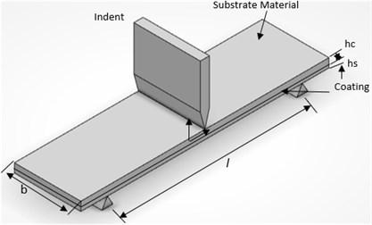
It follows the equivalent von Mises yield criteria coupled with an isotropic work hardening scheme. The Material properties employed for FEM simulations are mentioned in Table 1. For solid structures, 3D modeling VISCO107 is used. This element is described by eight nodes and at each node degrees of freedom are three. 3 DOFs are translations in the node direction of -axis, -axis and -axis. For meshing 2900 elements were employed, refinement of grid been done near the plane where load is applied. Load was acted at the centre of the metal sheet in the form of displacement to get same condition of loading which is done in experimental work. At the left side of plate displacement was fixed in vertical direction. For FEM simulations the size of workpiece and force application conditions are similar as in experiment reported in reference paper.
3. Young’s modulus calculation
Young’s modulus for given model can be written as [1, 9, 10]:
where – Moment of inertia of sheet metal (substrate), – Moment of inertia of coating material, – Acted load, Distance between frictionless supports at two extremities, – Displacement of the sheet metal and coatings during the bend testing, – Width of sheet metal and the coating materials.
Where moments of inertias are:
Fig. 2FEM predictions for 3D models: a) with coatings, b) without coating
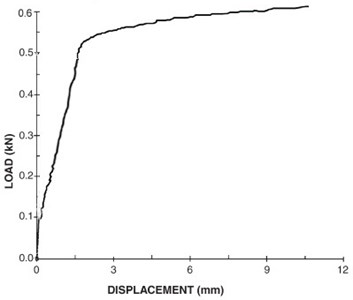
a)
b)
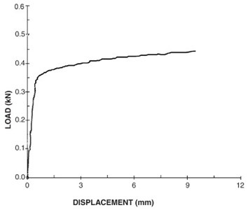
Fig. 3Experimental results of sample with and without coating [1]
![Experimental results of sample with and without coating [1]](https://static-01.extrica.com/articles/20400/20400-img4.jpg)
4. Results and discussions
Three-point bend test of Inconel 718 coating on Stainless steel substrate is carried out by using FEM simulation. Materials property is used for simulation is mentioned in Table 1. Load was applied at the substrate material which is a top side of model and coating is down side of model.
In Fig. 2 load vs displacement curve is shown. It is generated by FEM predictions for the sample on which bending test were done with and without coating conditions. In Fig. 3 load vs displacement curve is shown which is obtained from experimental results for coated and uncoated base materials. By checking Fig. 2 and Fig. 3 Finite Element Modelling simulation results matched closely with experimental values. This means that 3D model can be a convincing way to find out stress field for this present study. Bending test was done at constant strain rate and test continues until failure of coating surface was observed. Since young’s modulus and stiffness values of coating (Inconel 625) are higher than stainless steel, elastic characteristics of sheet metal with coating and without coating is not same. The reason for differences can be structural change of coating. The values for Elastic modulus of coating is calculated by using Eq. (1) which is mentioned in Table 1.
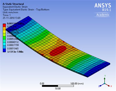
Fig. 4 shows FEM prediction for Equivalent (von-Mises) stress distribution in coating-substrate material during bend test. Stress in coating where values are highly distributed is spreads into the metal sheet region. Coating failure at interface is possible because mechanical properties as well as Young’s Modulus of coating are not same as metal sheet since it produces high strain at coating-substrate interface. Fig. 5. FEM simulation for Equivalent Elastic strain distribution during bend test. The elastic strain value is higher at centre of both coating-substrate material where it bends most at top and bottom. The coating fails in regions where high values of plastic strain produced, the overall failure occurs at coating and substrate interface.
Fig. 4FEM prediction for equivalent (von-Mises) stress distribution during bend test
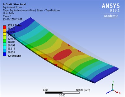
Fig. 5FEM simulation for equivalent elastic strain distribution during bend test
5. Conclusions
Inconel 718 on stainless steel is used for test. Three-point bend test are performed and load versus displacement graph were plotted. For stress analysis FEM simulation of bending tests were conducted. The FEM values of load vs displacement behaviour are studied and verified with a reference result. The 3D model is applied in the simulations. It is noticed that yield stress of substrate material is higher than the tensile stress of substrate and coating. Due to this reason there is initiation of crack at coating-substrate interface and it is propagated which leads to failure with applied load. Crack is formed due to difference in Young’s modulus in coating and sheet metals.
References
-
Arif A. F. M., Yilbas B. S. Three-point bend testing of HVOF Inconel 625 coating: FEM simulation and experimental investigation. Surface and Coatings Technology, Vol. 201, Issue 1, 2006, p. 1873-1879.
-
Al Anazia D., Hashmia M. S. J., Yilbas B. S. Three-point bend testing of HVOF AMDRY 9954 coating on Ti-6Al-4V alloy. Journal of Materials Processing Technology, Vol. 174, Issue 1, 2006, p. 204-210.
-
Yilbas B. S., Arif A. F. M., Gondal M. A. HVOF coating and laser treatment: three-point bending tests. Journal of Materials Processing Technology, Vol. 164, Issues 165-1, 2005, p. 954-957.
-
Planques Pierre, Vidal Vanessa, Lours Philippe, Proton Vincent, Crabos Fabrice, Huez Julitte, Viguie Bernard Characterization of the mechanical properties of thermal barrier coatings by 3 points bending tests and modified small punch tests. Surface and Coatings Technology, Vol. 332, Issue 25, 2017, p. 40-46.
-
Hidalgo V. H., Varela J. B., Menendez A. C., Martinez S. P. Effects of thermal spray procedure and thermal fatigue on microstructure and properties of NiCrAlMoFe coating. Surface Engineering, Vol. 17, Issue 1, 2001, p. 512-517.
-
Kharghania N., Guedes Soaresa C., Tsouvalis N. G. Experimental and numerical study of the bolt reinforcement of a composite-to-steel butt-joint under three-point bending test. Marine Structure, 2018, https://doi.org/10.1016/j.marstruc.2018.08.009.
-
Zhang Hua, Yang Jian, Hu Jinlin, Li Xian, Li Mingwei, Wanga Chenglong An experimental and simulation study of interface crack on zinc coating/304 stainless steel. Construction and Building Materials, Vol. 161, 2018, p. 112-123.
-
Ghasemi M. A., Falahatgar S. R. Damage evolution in brittle coating/substrate structures under three-point bending using discrete element method. Surface and Coatings Technology, 2018, https://doi.org/10.1016/j.surfcoat.2018.11.068.
-
Charalambides P. G., Lund J., Evans A. G., Mcmeeking R. M. A test specimen for determining the fracture resistance of bimaterial interfaces. Journal of Applied Mechanics, Vol. 56, Issue 1, 1989, p. 77-82.
-
Murakami Yukitaka Stress Intensity Factors Handbook. Committee on Fracture Mechanics, The Society of Materials Science, Japan, 1992.
Cited by
About this article

