Abstract
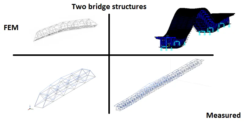
Dynamic measurements of two steel truss bridges for Structural Health Monitoring (SHM) were performed. The investigated bridges were: a single supported one span truss bridge and a multi-span truss bridge. Two possibilities of measuring setup were considered. A simple arrangement made up of one polygon has been used for data acquisition of the single span truss bridge. A more complex measuring setup made up of two polygons with up to 32 channels has been used for the large bridge with an entire length reaching up to 500 m. A connection of both measuring polygons was achieved by Wi-Fi antennas. The reason why the multi-span truss bridge was chosen for SHM is that the construction is nowadays overloaded. The dynamic measurements were done, ambient and semi-ambient data were analysed. After that, some mode-shapes were identified from the acquired data and then the data were compared with numerical calculations. Finally, experiences and conclusions from the ambient data measurement are summarized.
Highlights
- The used measuring system proved that it is suitable for vibration measurements of small and large bridge structures as well.
- The presented measurements can be used as a comparative basis for future repeated measurements for the SHM purposes.
- In the case of important and large bridge structures, ambient vibrations are the easiest way how to obtain data.
1. Introduction
This paper is devoted to dynamic measurements of two steel bridges in Slovakia loaded by ambient vibrations. Operational Modal Analysis (OMA) has been done. The acquired and processed data could be used for Structural Health Monitoring (SHM) purposes. The selected bridges are of different age. The single span steel truss bridge (Bridge No. 1) was built in the early 1950s. The multi-span steel bridge (Bridge No. 2) is younger because it has been in operation since 1985. On the other hand, the construction of the bridge is overloaded because the designed capacity was originally 50 000 cars per day and now, the amount of passing vehicles has about doubled. This traffic increase can cause problems with the fatigue resistance of important structural details of the bridge structure. In many cases, lack of long-lasting maintenance or periodic inspection can result in later expensive and complete reconstruction. A similar situation occurred in Slovakia where a temporary bridge, built after WWII, was demolished in 2013 and a new structure was built in 2015. In addition, the collapse of bridge structures during operation, apart from risking many lives, may also cause important economic losses. The losses are mainly due to the interruption of the communication network. Besides that, dynamic measurements can be also used for buildings [1, 2].
The above facts were confirmed by many researchers [3-8]. A lot of work has been devoted to SHM to satisfy the increasing demands on safety and on reduction of the maintenance costs of new or obsolete bridges. That is why modern types of SHM are advancing in the developed countries, as in [9]. The dynamic measurements are a necessary part of SHM.
This paper consists of more sections. Section 2 introduces the bridges which were measured; Section 3 describes the used measurement setup; Section 4 deals with the results of dynamic measurements; and finally, the main conclusions are presented in Section 5.
2. Description of bridges
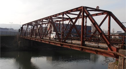
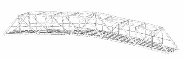
The bridge is in the western part of Slovakia and its exact location is in the city Nove Mesto nad Vahom. It connects the two sides of the Vah River channel. The steel truss bridge has one span with a length of 51.3 m. Two steel trusses with a height of 4.8 m and 4.58 m apart from each other form the bearing structure (Fig. 1). The bridge deck consists of concrete panels with a height of 250 mm. Pedestrians, cyclists and cars can use the bridge. The maximum weight of one vehicle is 15 000 kg. The speed is limited to 15 km per hour.
Fig. 1The single span truss bridge (Bridge No. 1)
Before the dynamic measurements, a Finite Element (FE) model was created as the first part of SHM in accordance with [10]. The preparation of the FE model started with the check of the bridge. The control was done by visual inspection of each member of the structure.
The second bridge was completely built in 1985 near the Bratislava’s port. The road-rail bridge crosses the Danube River. A highway is situated at the upper level, which is a part of the Slovak Highway D1 from Bratislava to Kosice. The present number of vehicles passing the bridge makes the Port Bridge the most used bridge in Slovakia. Such a traffic increase should be monitored. A double-track railroad is placed at the lower level of the bridge. At the same level, there are two cantilever ways designed for pedestrians, cyclists and services.
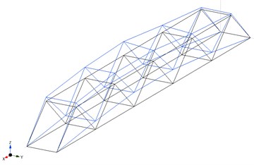
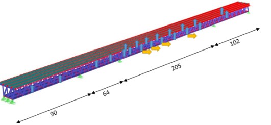
The bridge has a total length of 461 m with continuous four spans. The lengths of the spans are about: 102 m, 205 m (Fig. 2), 64 m and 90 m. Three steel trusses with a height of 11.7 m and 6.5 m apart from each other form the superstructure.
Fig. 2The multi-span truss bridge (Bridge No. 2)

3. Used measurement system
The selected bridges have a difficult cross-section and quite long spans, so a suitable system for measurements had to be designed. Finally, the designed setup, like the BRIMOS system [11], can measure vibrations at 32 points along the bridge structure. Besides that, the system can acquire temperature at 8 various places. The complex system using National Instruments’ equipment consisted of the following devices: National Instruments (NI) CompactRIO (cRIO) 9067 with four input/output (I/O) modules NI 9234 and two modules NI 9211. NI cRIO 9074 with up to three I/O modules NI 9234 (Fig. 3) and NI 9144 with also two I/O modules NI 9234. NI 9234 module represents a 4-channel, ±5 V, 24-Bit IEPE module for vibration measurements [12]. NI 9211 module is used for temperature measurements. The module is a 4-channel, ±80 mV, 24-Bit module for thermocouples. The main components (notebook, cRIO devices) were connected to a network switch via Wi-Fi antennas or via FTP network cable. The tested length of the connection cable was up to 100-meters long. The synchronization between the cRIO devices was the most problematic task. The used sample rate of the measurement system was optimized to 2048 samples per second because all measured data were saved on the main unit cRIO 9067 (Fig. 3). The chosen sampling rate was enough to measure the real structures and the necessary synchronization was constantly stable.
Fig. 3The cRIO 9074 with three NI 9234 modules connected via Wi-Fi antenna

4. Operational modal analysis (OMA)
The measured and pre-processed data were analysed in the ModalVIEW software. Software possibilities (stabilization charts) were used for extracting modal parameters as natural frequencies, damping ratios and corresponding mode-shapes. Stabilization charts were calculated using the Stochastic Subspace Identification (SSI) method. The method is suitable when input signals are unmeasured or cannot be measured [13] and only output data are available – ambient vibrations.
4.1. Bridge No. 1
Only one cRIO 9067 device was used for the first measurement. The other device did not have to be used because of the short span of the investigated bridge. 16 accelerometers were placed on the structure to identify global mode-shapes and corresponding natural frequencies (eight sensors in horizontal direction and eight sensors in vertical direction). Other four accelerometers were mounted on the first two tensile diagonals of the bridge. All accelerometers were mounted with magnets to the structure. The temperature of the structure and the air-temperature were also acquired for future comparison and to find their possible impact on the natural frequencies.
Ambient vibrations were monitored. The types of loads were registered during the 5-minutes’ measurement time. Ambient vibrations appeared in the acquired data (without load caused by moving cars, cyclists, etc.). The operational modal analysis was performed afterwards, and the result was compared with the FE model of the bridge (Fig. 4).
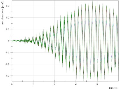
The details of the applied loads (moving cars, cyclists and pedestrians) showed that in one moment (Fig. 4), the bridge was excited by a lonely runner (Fig. 5). The runner left the bridge after 8 s and then the bridge started to damp down. During this action, the runner excited the bridge in the second global mode-shape (in -direction – Fig. 4).
We have checked from Fig. 5 that the analysis of ambient vibrations gives the same result as the semi-ambient excitation, e.g. caused by the lonely runner. It is also helpful if it is possible to repeat the loading by runners and then the comparison of the data from two various measurements can be useful for SHM purposes – possible damage detection from changes in frequencies, mode-shapes or damping characteristics.
Fig. 4The 2nd identified mode-shape: a) measurement in 2016 (f= 3.01 Hz), b) FEM model (f= 3.04 Hz)
a)
b)
Fig. 5The measured vertical accelerations from loading by a lonely runner
4.2. Bridge No. 2
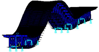
The mentioned complex system was also used for the measurements of the bridge No. 2. Both NI cRIO devices have been used. The polygon on the upstream side had four NI 9234 modules that represented a possibility to use 16 channels for measurements. On the other side two NI 9234 modules were used. There were eight channels for measurement of accelerations. Fig. 6 shows the location of the used accelerometers. Totally, 22 accelerometers were used for data acquisition in -direction. Vibrations in -direction were measured in four places. These 26 accelerometers were placed at the bottom part of the bridge cross-section (Fig. 6). The other four sensors were at the top part in the -direction. The temperature was also recorded.
Fig. 6The location of accelerometers at the bottom part in 2017
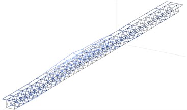
Because of the stated importance of the bridge, it could not be closed, and only ambient vibrations could be measured. After the measurement, the recorded data were processed in the software NI DIAdem and ModalVIEW. Comparison of the first mode-shape and the calculated one is shown in Fig. 7.
Fig. 7The 1st identified mode-shape: a) measurement in 2017 (f= 0.89 Hz), b) FEM model (f= 0.78 Hz)
a)
b)
The initial measurement was analysed in [14]. Spectra in another frequency range were also compared in [14]. The range was considered from 5 to 15 Hz. Fig. 8 shows the calculated and measured spectra for 2 points where accelerometers were placed. The place was in the middle of the longest span of bridge No. 2. The two presented measurements show that ambient vibration measurements can lead to comparable results as in the FE calculations.
Fig. 8The spectra: a) measurement in 2015, b) FEM model [14]
![The spectra: a) measurement in 2015, b) FEM model [14]](https://static-01.extrica.com/articles/20419/20419-img10.jpg)
a)
![The spectra: a) measurement in 2015, b) FEM model [14]](https://static-01.extrica.com/articles/20419/20419-img11.jpg)
b)
5. Conclusions
Comparisons of the calculated and the measured natural frequencies and mode-shapes show a relatively good coincidence for both structures which were described in this paper. The used measuring system proved that it is suitable for vibration measurements of small and large bridge structures as well. The presented measurements can be used as a comparative basis for future repeated measurements for SHM purposes. In the case of large bridge structures (when they represent important part of the road network), ambient vibrations are the easiest way how to obtain data. It was proven that the data acquired from ambient vibrations can also be used for experimental modal analysis. For comparative purposes roughly identified traffic load cases can be used as well if they are correctly recorded and reproduced.
References
-
Diaferio M., Foti D., Giannoccaro N. I., Ivorra S. Optimal model through identified frequencies of masonry building structure with wooden floors. International Journal of Mechanics, Vol. 8, Issue 1, 2014, p. 282-288.
-
Kowalska-Koczwara A., et al. Vibration-based damage identification and condition monitoring of metro trains: Warsaw metro case study. Shock and Vibration, Vol. 2018, 2018, p. 1-14.
-
Strauss A., Frangpol D. M., Bergmeister K. Assessment of existing structures based on identification. Journal of Structural Engineering, Vol. 136, Issue 1, 2010, p. 86-97.
-
Bayer J. A concept for testing and monitoring of building structures – theoretical case study. Proceedings of the 23rd International Conference Engineering Mechanics, Brno, Czech Republic, 2017, p. 122-125.
-
Li H. N., Ren L., Jia Z. G., Yi T. H., Li D. S. State-of-the-art in structural health monitoring of large and complex civil infrastructures. Journal of Civil Structural Health Monitoring, Vol. 6, Issue 1, 2016, p. 3-16.
-
Seo J., Hu J. W., Lee J. Summary review of structural health monitoring applications for highway bridges. Journal of Performance of Constructed Facilities, Vol. 30, Issue 4, 2016, https://doi.org/10.1061/(ASCE)CF.1943-5509.0000824.
-
Bayraktar A., Altunisik A. C., Turker T. Structural health assessment and restoration procedure of an old riveted steel arch bridge. Soil Dynamics and Earthquake Engineering, Vol. 83, 2016, p. 148-161.
-
Poprawa G., Salamak M., Pradelok S., Lazinski P. Operational modal analysis in model updating of a truss railway bridge. 7th International Operational Modal Analysis Conference, 2017.
-
Farrar C. R., Worden K. An introduction to structural health monitoring. Philosophical Transactions of the Royal Society, Vol. 365, 2006, p. 303-315.
-
Chen S., Su M., Liu Y., Wang Q. Vibration remote monitoring system of continuous steel truss girder for the Wuhu Yangtze river bridge. 14th World Conference on Earthquake Engineering, Beijing, China, 2008.
-
Wenzel H., Pichler D. Ambient Vibration Monitoring. John Wiley & Sons Ltd., Chichester, UK, 2015.
-
Mitra A. C., Banerjee N. A LabVIEW-based data acquisition system in a quarter car test rig to optimize vehicle suspension system. Intelligent Computing and Applications, Vol. 343, 2015, p. 593-601.
-
Peeters B., De Roeck G. Reference-based stochastic subspace identification for output-only modal analysis. Mechanical Systems and Signal Processing, Vol. 13, Issue 6, 1999, p. 855-878.
-
Aroch R., Sokol M., Venglar M. Structural health monitoring of major Danube bridges in Bratislava. Procedia Engineer, Vol. 156, 2016, p. 24-31.
-
Bhalla S., Moharana S. Modelling of piezo-bond structure system for structural health monitoring using EMI technique. Key Engineering Materials, Vol. 569, Issue 570, 2013, p. 1234-1240.
Cited by
About this article

This paper was supported by the Slovak Research and Development Agency (SRDA), i.e. a Grant from Research Program No. APVV-0236-12 and by the Scientific Grant Agency of the Ministry of Education, science, research and sport of the Slovak Republic and the Slovak Academy of Sciences – grant VEGA 1/0773/18. It was also supported by Grant from Research Program of Slovak University of Technology – Excellent Teams of Young Researchers 2018.
