Abstract
Longitudinal tension and compression deformations of a tunnel are caused by longitudinal non-uniform displacement of surrounding rock under earthquakes, and the longitudinal equivalent rigidity is one of the most important mechanical performance index in the seismic response analysis of a TBM tunnel. The back analysis of a jointed TBM tunnel lining rigidity under earthquakes was conducted, in which segments and joints are simulated by finite elements. The results show that the rigidity ratio of segment element to joint element decreases exponentially with the increase of shear modulus of surrounding rock when subjected to small earthquake (0.1 g), but the rigidity ratio of segment element to joint element is almost unchanged with the increase of shear modulus of surrounding rock when subjected to strong earthquake (0.3 g). Therefore, when a jointed TBM tunnel lining is equivalent to a continuous beam, the resistance spring of surrounding rock in parallel with the joint spring is introduced to establish the evaluation model of the equivalent longitudinal rigidity of the jointed TBM tunnel lining under earthquakes.
1. Introduction
Recent earthquake events show that tunnels are vulnerable to unrecoverable damage in strong seismic areas, the anti-seismic issue of tunnels arouses much attention from earthquake engineers around the world [1]. The TBM tunnel is a linear underground structure, in which jointed segmental precast concrete linings connected by steel bolts. In seismic response analysis of TBM tunnels, one of the major difficulties lies with the proper simulation of the structural behavior of the segmental tunnel lining. One way to deal with this issue is to consider the tunnel lining as a continuous straight beam in the longitudinal direction, while considering the tunnel lining as a continuous ring beam in the transverse direction, with a discounted rigidity. Tunnels do not cause self-excited vibration under earthquakes but are controlled by the surrounding rock deformation. Therefore, it is very important to study the effect of rock resistance on equivalent stiffness of a jointed TBM tunnel lining. Lee and Ge [2] studied the effect of rock resistance on equivalent stiffness of ring beam. Based on field monitoring data during earthquakes and numerical simulation analysis, Suzuki [3] proposed an equivalent rigidity calculation model of straight beam, with consideration of rock resistance, but the non-linear mechanical behavior of interface between surrounding rock and tunnel lining was not considered. In this paper, the back analysis of a jointed TBM tunnel lining rigidity under earthquakes was conducted; then, based on the analysis results, an evaluation model of the longitudinal equivalent rigidity of the jointed TBM tunnel lining was established.
2. Numerical simulation model and results
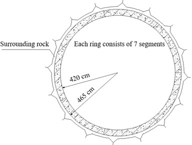
Fig. 1 shows that longitudinal tension and compression deformations of a tunnel are caused by longitudinal non-uniform displacement of the surrounding rock under seismic waves. As shown in Fig. 2, a TBM tunnel with outer diameter of 9.3 m made of reinforced concrete segments with a thickness of 45 cm was analysed in this paper. Each ring consists of 7 segments with a width of 1.8 m. The density of segment is 2500 kg/m3, while the elastic modulus is 32.5 GPa and Poisson’s ratio is 0.2. The tensile rigidity of joints is 4.83×10⁶ kN/m, thus the elastic modulus of the joint element in the axisymmetric finite element model is as follows:
wherein, is the tensile rigidity of joints; is the width of the joint, in this paper, 2 cm is taken; is the sectional area of segment.
Fig. 1A tunnel subjected to alternating tension and compression during an earthquake
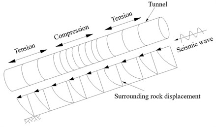
Fig. 2Schematic diagram of the jointed TBM tunnel lining
ABAQUS finite element method software was selected to back analyse the longitudinal rigidity of the jointed TBM tunnel lining under earthquakes [4]. An axisymmetric finite element model for back analysis is established by taking the longitudinal center line of the tunnel as the symmetrical axis, in which the mechanical behavior of interface between surrounding rock and tunnel lining is simulated by contact element. The discretization and boundary conditions of the axisymmetric finite element mesh are shown in Fig. 3. The calculation parameters of tunnel lining in axisymmetric finite element are shown in Table 1. Table 2 shows typical physical mechanical parameters of surrounding rocks at all levels.
Fig. 3The computational model for back analysis of the jointed TBM tunnel lining rigidity
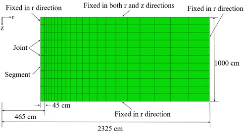
Table 1Calculation parameters of tunnel lining in axisymmetric finite element model
Material | Density (kg/m3) | Elastic modulus (MPa) | Poisson’s ratio |
Segment | 2500 | 32500.00 | 0.2 |
Joint | – | 7.72 | 0 |
Table 2Typical physical mechanical parameters of surrounding rocks at all levels
Level | Density (kg/m3) | Elastic modulus (GPa) | Poisson’s ratio |
Ⅰ | 2700 | 35 | 0.18 |
Ⅱ | 2600 | 20 | 0.25 |
Ⅲ | 2400 | 10 | 0.3 |
Ⅳ | 2100 | 3 | 0.35 |
Ⅴ | 1800 | 1.2 | 0.4 |
Ⅵ | 1600 | 0.5 | 0.45 |
When the seismic acceleration is small, the relative displacement between surrounding rock and tunnel lining is very small. It can be considered that there is a linear relationship between shear stress and relative shear displacement at the interface between surrounding rock and tunnel lining [5]. In this case, the linear elastic cohesive model is used to simulate the shear mechanical behavior between surrounding rock and tunnel lining:
wherein, is the shear stress of the interface; is the relative shear displacement, and is the shear rigidity coefficient.
Large slippage occurs between surrounding rock and tunnel lining when subjected to strong earthquake excitation. In this case, the Coulomb friction model is used to simulate the shear mechanical behavior between surrounding rock and tunnel lining:
wherein, is the friction coefficient of the interface; is the normal stress of the interface.
In this paper, the seismic acceleration of a small earthquake and the seismic acceleration of a strong earthquake are 0.1 g and 0.3 g, respectively. The uniform seismic acceleration is transformed into the node force in the form of the body force and applied to the nodes of surrounding rock in the finite element model along the direction [3].
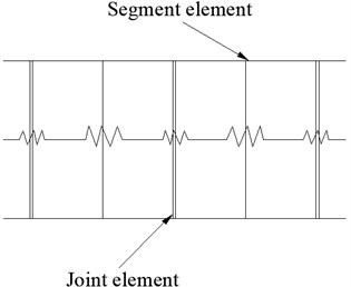
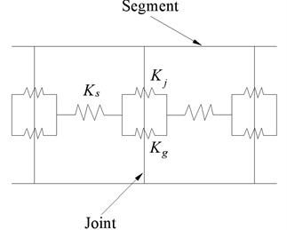
As shown in Fig. 4, because the segment element is in series with the joint element, the rigidity ratio of segment element to joint element is:
wherein, is the deformation of segment element, is the deformation of joint element, is the rigidity of segment element, and is the rigidity of joint element.
Fig. 4Calculation model of rigidity ratio between segment and joint element
As shown in Fig. 5, the rigidity ratio of segment to actual joint structure is 46.8, thus the apparent rigidity of joint is far greater than its structural rigidity. The rigidity ratio of segment element to joint element decreases exponentially with the increase of shear modulus of surrounding rock when subjected to small earthquake (0.1 g). Therefore, the exponential function is used to fit the calculated values:
Fig. 5The relationship between rigidity ratio and shear modulus (0.1 g)
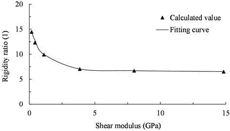
Fig. 6The relationship between rigidity ratio and shear modulus (0.3 g)
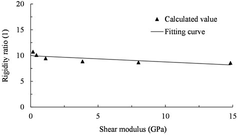
As shown in Fig. 6, the apparent rigidity of joint is also far greater than its structural rigidity. The rigidity ratio of segment element to joint element is almost unchanged with the increase of shear modulus of surrounding rock when subjected to strong earthquake (0.3 g). Therefore, the linear function is used to fit the calculated values:
3. Calculation model of equivalent rigidity
Due to the surrounding rock resistance, the joint cannot expand freely, resulting in the apparent rigidity of the joint is far greater than its structural rigidity under earthquakes. To reflect the restraint effect of surrounding rock, as shown in Fig. 7, the restraint rigidity of surrounding rock is introduced. The longitudinal equivalent compression rigidity of a jointed TBM tunnel lining is [6]:
wherein, is the elastic modulus of segment, is the sectional area of segment.
The longitudinal equivalent tension rigidity of a jointed TBM tunnel lining is:
Fig. 7Calculation model of equivalent rigidity considering rock resistance
4. Conclusions
1) The rigidity ratio of segment element to joint element decreases exponentially with the increase of shear modulus of surrounding rock when subjected to small earthquake (0.1 g), but the rigidity ratio of segment element to joint element is almost unchanged with the increase of shear modulus of surrounding rock when subjected to strong earthquake (0.3 g).
2) When a jointed TBM tunnel lining is equivalent to a continuous straight beam in the longitudinal direction, the resistance spring of surrounding rock in parallel with the joint spring is introduced to establish the evaluation model of the equivalent longitudinal rigidity of the jointed TBM tunnel lining under earthquakes.
References
-
Li T. Damage to mountain tunnels related to the Wenchuan earthquake and some suggestions for aseismic tunnel construction. Bulletin of Engineering Geology and the Environment, Vol. 71, 2012, p. 297-308.
-
Lee K. M., Ge X. W. The equivalence of a jointed shield-driven tunnel lining to a continuous ring structure. Journal of Canadian Geotechnical Engineering, Vol. 38, 2001, p. 461-483.
-
Suzuki T. A study on the evaluation of earthquake resistance of shield-driven tunnels in axial direction. Journal of JSCE, Vol. 441, Issue 18, 1992, p. 137-146.
-
Hibbit D., Karlsson B., Sorenson P. ABAQUS Analysis User’s Manual. Version 6.5. Pawtucket, RI, Hibbit, Karlsson and Sorenson Inc., USA, 2004.
-
Sun Q., Liu W., Li J. Soil spring constant of buried pipeline-soil longitudinal dynamic interaction. Journal of Tongji University (Natural Science), Vol. 40, Issue 8, 2012, p. 1123-1128.
-
Kawashima K. Seismic Design of Underground Structures. Kajima Press, Tokyo, 1994.
About this article

This research was supported by the National Program on Key Basic Research Project of China (973 Program) (Grant No. 2015CB057906).
