Abstract
The work is devoted to the use of radar interferometry for measurements of the dynamic response of a bridge. Interferometric radar IBIS-S provides financially affordable way of monitoring bridges based on the measurement of dynamic displacements without traffic limitation. The dynamic response of the bridge is assessed on the basis of the dynamic coefficient.
1. Introduction
Structural health monitoring of bridges is very important today mainly because of their growing age and overloading. Measuring the dynamic response of bridges using conventional sensors (e.g. accelerometers) often requires partial or total traffic restrictions on the bridge, which can be expensive. Radar interferometry is an interesting alternative to displacement measurement because of several advantages over conventional sensors. One of the advantages is the possibility of measuring without using a large number of cables. Radar measurements are particularly suitable for measuring the displacements of structures with restricted access or in situations where very rapid remote sensing of the structure is required. That is why we decided to propose financially affordable monitoring based on the measurement of the dynamic response of various structures without traffic restrictions using the IBIS-S interferometric radar.
2. Advantages and disadvantages of radar interferometry
Radar interferometry is currently a very widespread technology and many scientific teams consider this method of measurement very convenient [1-7]. Many authors point to a number of advantages over the use of conventional sensors [2, 7]. One of the advantages is the direct measurement of the structure displacement without the need for numerical integration. The radar transmits microwave signals with high frequency. Based on the time difference between the transmitted and reflected signals, distances are determined. Displacements of the reference points along the field of view of the radar sensor are measured in radial direction (radial displacement). Therefore, it is necessary to evaluate the displacement in vertical or horizontal direction, on the basis of previous knowledge about the direction of movement of the reference point. It is necessary to perform an initial measurement (position of the device relative to the measured structure) [8].
The device is very sensitive to the environmental impacts of the environment (vegetation, weather, etc.). Therefore, it is important to find a suitable place for the location of the radar. Both the preparation and the measurement itself are very fast and relatively accurate (manufacturer’s specified measuring accuracy of 0.1 mm) [4, 8]. The accuracy of the measurement depends on the signal to noise ratio of the point being considered. In addition to the effects of the environment (which can be eliminated), accuracy also depends on the distance of the measured point. The greater the distance of the measured point, the lower the intensity of the reflected signal. This can change the measurement accuracy to a few millimeters.
One of the disadvantages of this device is the imaging capability of only 1D space, which may cause an error in measuring different points at the same distance from the radar.
When the structure has too many points or, on the contrary, has no points that would naturally reflect the signal back to the radar, or the structure is far, the reflectivity of the target can be increased by using reflectors.
3. Dynamic response of the bridge
This paper is devoted to measuring the dynamic displacements of railway bridges across the Váh river. The structure consists of three bridge spans (Fig. 1): two side spans of 29.40 m and the middle span of 57.40 m.
Fig. 1Diagram of bridge objects

3.1. Measurement of displacement using interferometric radar
Dynamic displacements measurements were repeatedly performed using the IBIS-S interferometric radar with Type 3 antennas from IDS [8]. At first, it was necessary to find the right location for the radar providing sufficient stabilization for the device. For each of the three objects, it was necessary to find a suitable location and remove the environmental impacts. The measurements were repeated several times over eight months. All measurements were made from the same position, as much as possible.
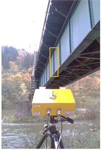
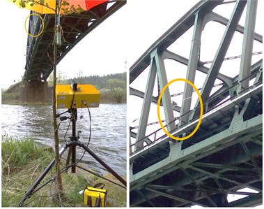
To measure the displacements of the side spans reflectors were not necessary. The signal was naturally reflected back to the radar from connections of the walls of a girder (Fig. 2(a)). Reflectors were placed at the center of the span on the truss girder (middle span) to increase the reflectance of the measured points (Fig. 2(b)).
Fig. 2Measured points: a) at box girder spans, b) at truss girder span

a)

b)
Each measurement was performed in dynamic mode with a sampling rate of 200 Hz. The total measuring range was divided into radial areas with a resolution of 0.75 m. The radial displacements were recalculated to the vertical direction. Subsequently, they were plotted as graphs (Fig. 3(b), (d)) and further analyzed.
Fig. 3a) S2 – Train 523 position in 2.4 s, b) dynamic displacement record – S2 – Train 523, c) S1 – Train 604 position in 2.4 s, d) dynamic displacement record – S1 – Train 604

a)

b)

c)

d)
The measured displacement time histories were compared with numerically calculated static displacement from specific train types.
3.2. Numerical models
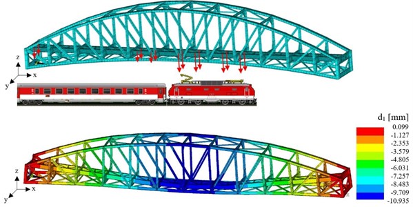
For comparison of the results obtained from the measurements and to perform more detailed calculations, finite element models of all objects were prepared. They were based on the original project documentation. Dimensions were verified in situ. Numerical models were updated and verified according to measurements using accelerometers and radar (Fig. 4).
3.3. Evaluation of dynamic factors
We can conclude that the experimental response of the object S2 (Fig. 4) is in a good agreement with the predictive values from numerical (FEM) analysis (Fig. 3(b), Fig. 5).
Fig. 4Theoretical static displacement of the structure S2 – Train 523 – at time 2.4 s

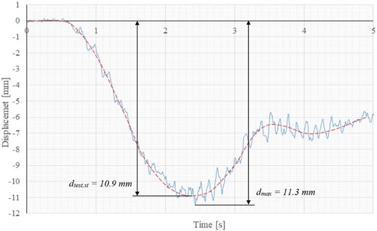
Fig. 5Detail of displacement record – S2 – Train 523

We consider this to be a very positive finding, because we will be able to perform parametric studies of the impact of possible defects on the dynamic response (e.g. eigenfrequencies, eigenmodes) on a calibrated numerical model.
From the displacement record (Fig. 5.), the maximum value of the measured displacement caused by passing the train was determined and the maximum value of the quasi-static displacement . These parameters were needed to calculate the dynamic factor according to the equation [9]:
The dynamic test was evaluated according to the approximate standard criterion [9]:
where is the load efficiency given by the equation:
The maximum theoretical displacement at the center of the bridge field was calculated using a numerical model, with LM71 load model applied [10]. The value of was equal to 31.5 mm.
The dynamic factor for commonly maintained tracks is given by the equation [9]:
where is the determinant length for the corresponding dynamic factor. For simply supported beams, is equal to the span in the direction of the main girder. Dynamic factor for truss bridge (S2) is:
The evaluation according to criterion Eq. (2) can be found in Table 1 column 8. Values less than Eq. (5) fulfilled the criterion. In this way, records of displacements of all spans of the bridge were processed. For each object, the dependence of the dynamic factor on the train speed was also evaluated [6, 10].
Table 1Evaluation of displacement records – S2
Test | Train | Velocity [km/h] | [mm] | [mm] | [–] | Assessment Eq. (2) | |
1 | 523 (1HKV+5V) | 75 | 10.88 | 11.35 | 1.04 | 1.01 | FULFILED |
2 | 3425 (1HKV+4V) | 77 | 9.03 | 9.27 | 1.03 | 1.01 | FULFILED |
4. Conclusions
In conclusion, we can say that the use of radar interferometry to measure the dynamic response of bridges has both advantages and disadvantages. The biggest advantage is the direct displacement measurement without the need for numerical integration. Furthermore, the use of this technology is suitable for measuring the displacements of structures with restricted access or in situations where very fast remote inspection of the structure is required. All this is also possible without restrictions on traffic on the bridge. Finding a suitable location for radar placement is initially rather difficult because of high sensitivity to environmental influences. However, this disadvantage can often be eliminated by removing interfering objects from the radar measuring range beforehand. As soon as a suitable location for radar stabilization is found and prepared, the preparation for measurement and the measurement itself are very fast and quite accurate.
References
-
Gocal J., et al. Determination of Displacements and Vibrations of Engineering Structures Using Ground-Based Radar Interferometry. Wydawnictwa, Krakow, 2013, p. 267.
-
Kuras P., et al. Advantages of Radar Interferometry for Assessment of Dynamic Deformation of Bridge. Bridge Maintenance, Safety, Management, Resilience and Sustainability, Taylor and Francis Group, London, 2012, p. 885-891.
-
Gentile C. Application of Radar Technology to Deflection Measurement and Dynamic Testing of Bridges. Radar Technology, Guy Kouemou, IntechOpen, 2010, https://doi.org/10.5772/7178.
-
Talich M., Glöckner M., et al. Proven Technology for Determination of Horizontal Movements of High-Rise Buildings by Ground Interferometric Radar. Verification Measurements Performed. Institute of Information Theory and Automation, Prague, 2014.
-
Raventós J., Couso C., García J. The use of InSAR technology to monitor ground and structural displacement. Proceedings of the 7th International Conference on Engineering Surveying, Lisabon, Portugal, 2017, p. 303-310.
-
Beben D. Experimental study on the dynamic impacts of service train loads on a corrugated steel plate culvert. Journal of Bridge Engineering, Vol. 18, Issue 4, 2013, p. 339-346.
-
Sokol M., Venglár M., Ároch R., Kopáčik A., Kyrinovič P., Erdélyi J., Šišmišová Z., Lamperová K. Traffic response pattern of cable-stayed bridge as a comparison tool for SHM. 39th IABSE Symposium – Engineering the Future, Vancouver, Canada, 2017.
-
IBIS-S Controller Software ver. 02.02.000 – User Manual. Ingegneria Dei Sistemi (IDS) S.p.A., Pisa, 2010.
-
STN EN 1991-2. Actions on Structures, Part 2: Traffic Loads on Bridges, EN 1991-2/NA, 1991.
-
STN 73 6209. Load Testing of Bridges, SÚTN Bratislava, 1987.
Cited by
About this article
This paper has been supported by the grant No. 1/0749/19 provided by VEGA Agency of Ministry of Education, Science, Research and Sport of the Slovak Republic. It was also supported by grant from research program of Slovak University of Technology – Excellent teams of young researchers 2018.
