Abstract
The problem is formulated for the motion of a solid body (material particle) along a rough flat surface that performs rotary harmonic oscillations as a solid body around an axis lying in or outside the plane. This problem is of interest when designing new process machines to be used in the processing of natural and technogenic materials. It is also directly applicable to the problem of transportation of loose goods by sea in rolling conditions. The paper considers continuous motion of a particle along a vibrating surface without separation. The nonlinear differential equation obtained is significantly more complicated than the equation for the case of translational surface oscillations, which is well studied in the existing literature. This complication is due, in particular, to the presence of the centrifugal force of inertia and the Coriolis forces, as well as to the time dependence of the angle of inclination of the plane. The case when these forces may be neglected is considered in detail. It is shown that application of effective parameter values allows reducing the problem to the case of translational vibration. It is also shown that the motion laws for a body under rotary oscillations are significantly different from those applying to the motion under translational vibration. They must also be taken into account when analyzing the behavior of loose cargo on sea vessels in rolling conditions.
1. Introduction
The effect of transportation of solid and granular bodies on a vibrating rough surface has gained wide practical use. The theory of this effect is relatively well developed for the cases where the surface performs plane-parallel translational oscillations [1, 2].
This paper focuses on a more complicated problem of vibrotransportation over a rough surface that performs non-translational vibrations. It may be expected that such a study will serve as the basis for expanding the applications for vibration equipment.
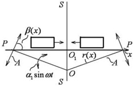
The motion of a flat solid particle is considered as the basic model in the theory of vibrotransportation. Even in this form, the problem leads to rather nonlinear “non-smooth” differential equations, which is due to the presence of the dry friction force and the unilateral constraint. The main objective is to find the average particle velocity for the oscillations period in stable steady-state modes. The problem of vibrotransportation over a surface under non-translational oscillations is even more complicated. This may be seen from Fig. 1 that shows the oscillations and the forces acting on the particle in its relative motion along the surface in the case of translational (Fig. 1(a)) and non-translational (Fig. 1(b)) oscillations (turns relative to a certain point O).
In the figure, (, ) is the moving coordinate system rigidly connected with the vibrating surface, is the force of inertia, is the tangential force of inertia in relative motion, and are the centrifugal and Coriolis inertial forces, is the force of gravity, is the normal response, is the dry friction force, is the angle of inclination of the surface to the horizon, and is the vibration angle.
As can be seen, with non-translational oscillations in relative motion, the centrifugal and Coriolis inertia forces are added. In addition, the term reflecting the influence of gravity becomes a function of time.
The article is structured as follows. First, the equations are obtained for the relative motion of a particle along the oscillating surface. Then, the conditions are identified, under which the centrifugal and Coriolis inertia forces in these equations may be ignored. It is shown that, for this case, which is characteristic of the problems of vibration technology, the use of new parameters allows reducing the problem to the well-studied case of translational surface oscillations. Further, the article provides the experimental results that allow establishing certain regularities of the emerging motions and considers the possible practical applications for the research results.
Fig. 1Particle on a vibrating rough surface: a) the case of translational vibration, b) the case of non-translational vibration
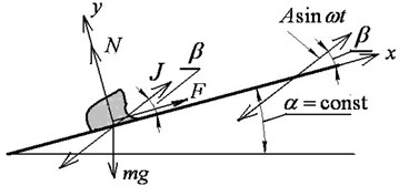
a)
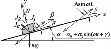
b)
2. Equations of motion
Consider the motion of a particle on a plane (see Fig. 2), located on a solid body , performing rotary oscillations according to the following law:
Around a certain center ( is the angle of inclination of the plane to the horizon, , ).
Fig. 2Forces in relative motion of a particle along a flat surface under non-translational oscillations
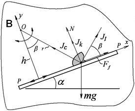
The equation of relative motion of the particle along the plane may be written as (with axis directed along and axis perpendicular to the plane):
here, is the dry friction force determined by the ratios of:
where and are, respectively, the coefficients of friction of rest and slip, and:
is the normal response.
The particle remains on the vibrating surface at 0, i.e.:
when the particle is at rest on the plane (), the friction force is determined from Eq. (2):
and therefore, according to the latter ratio Eq. (3), the particle continues to remain at rest on the plane at any time if . After the transformations, the latter inequality takes the form of:
Hereinafter, the upper signs refer to possible or actual forward motions of the particle , and the lower signs refer to possible backward motions 0, Equation of motion Eq. (2) of the particle along the plane, taking into account expressions Eqs. (1), (3) and (4), may be represented in the form of:
Note that, in this equation, and are the functions of the coordinate (see Fig. 2):
where is the distance from the oscillation center to the vibrating plane.
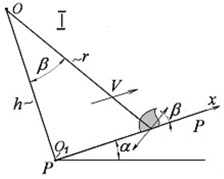
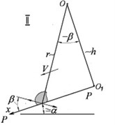
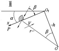
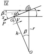
The formulas below refer to the case when the point is located above the plane and axis is directed away from the center of the plane towards the periphery (Fig. 3(a)). Assuming that axis is also always directed away from the center towards the periphery with the acute angle of β, as in the main case (Fig. 3(a)), then, in case II (Fig. 3(b)), in the formula should be replaced with ; in case III (Fig. 3(c)), should be replaced with ; and in case IV (Fig. 3(d)), should be replaced with and should be replaced with .
3. Simplification of the equation of motion, reduction to the problem of translational vibration
Eq. (8) is rather too complex for an analytical solution. Therefore, let us consider the possibilities of simplifying the solution. Note that the value of generally has the order of , and the magnitude of gravity has the order of tangential inertia. Then, the values of the centrifugal and Coriolis forces are of the order of as compared to gravity and the tangential inertial force. Therefore, if the amplitude of rotary oscillations of the body is relatively small, then the centrifugal force of inertia and the Coriolis force of inertia may be neglected as compared to other forces, and Eq. (8) and Eqs. (4) to (7) may be linearized relative to . In this case, these relations will take the following form:
is the vibration amplitude for the point of the plane with the coordinate .
Fig. 3Various relative arrangements of the plane and the oscillation center
This approximation is quite sufficient for application to problems of the theory of vibration devices and technologies, when is usually less than 20°. It is also generally sufficient in the problem of the behavior of loose cargo on ocean-going vessels in rolling conditions.
Another serious simplification is due to the fact that particle displacement during the oscillation period is relatively small, so that, when solving Eq. (12), the dependence of , and on may be considered purely parametrically, i.e. these values may be regarded as “locally constant”.
Further, if we introduce:
then the equation of motion Eq. (12) will take the following form:
This equation exactly coincides with the corresponding equation of particle motion on a plane under rectilinear and translational vibrations [1, 2]. Therefore, in order to calculate the average velocity of a particle, the formulas and tables given in these references may be used. The essential difference consists only in the need to take into account the dependence of on the direction of particle motion from the coordinate (parametrically).
4. Experimental data, comparison with the theoretical results
The purpose of the experiments was to verify certain basic results of the theoretical studies.
The experiments were carried out using a special vibration stand [3], enabling, in particular, obtaining rotary harmonic oscillations of the test table relative to a certain point (center of inertia of the table). These oscillations were excited by two nominally identical self-synchronizing unbalanced vibration exciters. When the rotors of the exciters rotated in the same direction, stable antiphase rotor rotation was observed.
The experimental setup is shown in Fig. 4.
A plywood rectangular plate 3 of 900×260 mm with the thickness of 8 mm was used. In the main series of experiments, the plate was placed horizontally at a distance 175 mm of above the center of rotary oscillations , coinciding with the center of gravity of the test table. Plate rigidity under vibrations was ensured using steel stiffeners. The rigidity of all fasteners used to secure the plate to the test table was also ensured.
Fig. 4Experimental setup (1 – vibration stand, 2 – unbalanced exciters, 3 – plate, 4 – stiffeners)
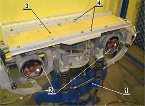
A copper cylinder with the diameter of 39 mm, height of 24.5 mm, and weight of 241.75 g was used as the moving load. The vibration frequency was 31.4 1/s (5 Hz), with the amplitude of angular oscillations of 1.3°.
The corresponding inclination angle of the plywood plate with the load was measured to determine the value of the friction coefficient 0.19.
The experiments consisted in measuring the time dependence for the displacement of the load, initially placed at the edge of the plate.
In accordance with the theory, in this case the load was moving from the edge towards the center of the plate (the case corresponding to Fig. 3(d)).
A stopwatch was used to record the time of passage of the load past the markings on the plate, located 5 cm, 10 cm, 20 cm, 30 cm, and 40 cm from the axis of symmetry on the plate surface. The measurement error for the displacement of the load on the plate did not exceed 5 %. The results are presented in Fig. 5.
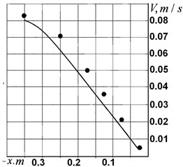
The data presented were used to determine the average velocity of the cylinder on the plane in various positions. The results of the calculations are represented by dots in Fig. 6. It also shows a solid line obtained by theoretical calculations similar to the example in item 4, with the data corresponding to the experimental conditions (with 0.19, 155 mm, 1.3°, , at the corresponding values of the coordinate ).
The calculations took into account that, when using self-synchronization, the average angle of inclination of the plane to the horizon may slightly change due to the always present variations in the parameters of electric motors and vibrators. Based on the estimates made, the corresponding deviation of was assumed to be –5°, so that –5°.
Fig. 5Displacement of a copper cylinder on a plywood plane depending on time t in experimental conditions (Fig. 3(d))
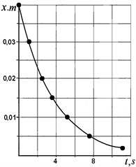
Fig. 6Average displacement velocity V depending on the coordinate x (• indicates experimental data; the line reflects the calculation result)
Given the degree of approximation in the use of the data (including the assumptions on equal friction coefficients of rest and slip), the degree of agreement between the theoretical and experimental results may be deemed satisfactory.
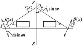
The second series of experiments was aimed at verifying the theoretical conclusion on the dependence of the direction of motion of a particle on the relative positions of the center of oscillations and the plane.
The results presented in Fig. 7 confirm this conclusion: when the center is located below the plane, the motion occurs from the center of symmetry of the plane towards its edge, with increasing average velocity; in the other case, the particle moves towards the center , its velocity decreases and the particle “gets stuck” at a certain short distance from the center . This is due to the fact that, as can be seen from Fig. 7, the closer the particle is to the center , the smaller the angle of will be. At 0, the particle either rests on the plane or, due to symmetry, experiences approximately the same displacements in both directions within the oscillation period.
Fig. 7Direction of particle motion under rotary oscillations of the plane: a) the center of oscillations O below the plane; b) the center of oscillations O above the plane
a)
b)
5. Conclusions
This paper presents the problem of motion of a body (particle) along a vibrating plane that performs non-translational (in particular, rotary) oscillations. This problem is of interest since it may be applied to the problems of vibration technologies. In addition, it arises when considering the specific behavior of loose cargo on ocean-going vessels under rolling conditions [4-8]. Note that the effective coefficient of dry friction during rolling periods may be further reduced through weak high-frequency oscillation effects or impacts on the load caused by the operation of the vessel machinery [9].It may be expected that the study performed will serve as an impulse for improvements and new inventions. It is shown that previously known results may be used to calculate the average velocity of a body upon introduction of certain transformed parameters. The paper presents the results of experiments illustrating the essential laws of the resulting motions that are consistent with theoretical data.
At the same time, the research potential of the problem is far from being exhausted. In particular, it is necessary to consider the particle motion conditions with separation from the vibrating surface. There are also cases when it is impossible to neglect the centrifugal and Coriolis inertial forces.
References
-
Blekhman I. I., Yu Dzhanelidze G. Vibrational Transportation. Nauka, Moscow, 1964.
-
Vibrations in Engineering: Handbook. Volume 4, Vibration Processes and Machines. Mechanical Engineering, Moscow, 1981.
-
Blekhman I. I., Vaisberg L. A., Vasilkov V. B., Lavrov B. P., Yakimova K. S. Universal vibration stand: Practical application in research, certain results. Scientific and Technical Bulletin of Saint-Petersburg State Institute of Technology, Vol. 3, 2003, p. 224-227.
-
Garkavy V. V. Ship Dynamics with Shifting Loads with Large Inclinations. Leningrad State Marine Technical University, 1991.
-
Moskalenko M. A. Methodological Foundations for Ensuring Design Safety of Ships. Vladivostok, Nevelskoy MSU, 2006.
-
Blekhman I. I., Demidov I. V., Semenov Yu A. On the problem of wrecking vessels with moving cargoes. Journal of Machinery Manufacture and Reliability, Vol. 46, Issue 1, 2017, p. 7-11.
-
Lin H., Yim S. C. S. Chaotic roll motion and capsize of ships under periodic excitation with random noise. Applied Ocean Research, Vol. 17, Issue 3, 1995, p. 185-204.
-
Nayfeh A. H., Khdeir A. A. Non-linear rolling of ships in regular beam seas. International Shipbuilding Progress, Vol. 33, Issue 379, 1986, p. 40-49.
-
Blekhman I. I., Vaisberg L. A., Vasilkov V. B. Mechanism of reducing effective dry friction under shock and vibration effects (to theory of technogenic seismic sources). Doklady Physics, Vol. 62, Issue 5, 2017, p. 253-256.
About this article

The work was carried out under grant No. 17-79-30056 of the Russian Science Foundation (Project of Mekhanobr-Tekhnika REC).
