Abstract
In this paper the hydraulic drive sensitive to the change of loading is offered to use under special conditions. Its distinctive feature is a smooth response to the abrupt change of loading from towed and lifted cargo, the impact of hydrometeorological factors. All this will improve the efficiency and reliability of the ship's deck devices. The obtained complex mathematical model of the investigated drive describes the unsteady dynamic processes that occur in the hydromechanical system and this model can be used in the study and design of such devices.
1. Introduction
Among ship’s deck devices it is necessary to allocate a class of mechanisms operating in special conditions. By special conditions we mean complex hydrometeorological conditions, unsteady dynamic loads from the towed load, changing of its shape, size, weight, transfer of the lifted cargo from one milieu to another. Such loads occur not only during transients, but also in conditions of steady-state operation. All this adversely affects the efficiency and reliability of the ship's deck equipment.
Hydromechanical drive has received the most application in ship deck devices. Its use ensures optimal operating parameters of speed change in a wide range, reversing, smooth regulation of revolutions and torque. However, to ensure the efficiency and reliability of such a drive under conditions of non-stationary loading, the use of the hydraulic drive sensitive to the loading variations is recommended [1].
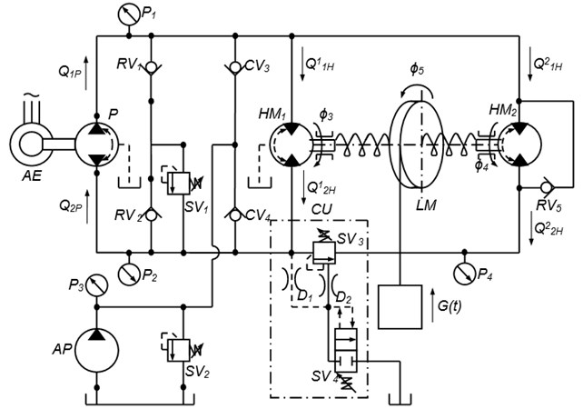
A special feature of the proposed hydraulic drive is the application of an additional hydraulic motor along with the main motor (Fig. 1). In case of sudden growth of external loading, when the pressure at the entrance to the P4 system exceeds the nominal P1, the control device is triggered, the working liquid enters the working chamber of the Hydromotor and includes it in parallel to the leading hydromotive . Control for the torque of the winding drum and the lifting speed occurs owing to the regulation of the flow and pressure of the working fluid.
The purpose of the given work is the development of the complex mathematical model of hydromechanical drive, providing the operation of ship’s deck equipment under special conditions.
At modeling of the investigated drive it is necessary to take into account non-evolutional process of towing and lifting of cargo arising at clinging of cargo to the unevenness of a bottom or other underwater objects, breakage of a rope, change of cargo parameters and length of a rope.
The integrated model of hydromechanical drive, sensitive to changes in loading should include fluid balance equations and equations of mechanical part motion.
The following assumptions were accepted when modeling the hydraulic system:
• The pump capacity is constant ();
• The total volume of the working fluid in each line and in the connecting channels at a given pressure is constant;
• The pressure connecting lines are short, so hydraulic resistance and wave processes in them can be neglected ( 0);
• The temperature and viscosity of the working fluid flow shall be taken as constant (, );
• The forces of dry friction are insignificant, therefore they can be neglected;
missing of cavitation and the flow gap in the system;
• The cavity pliability, and the compressibility of the working fluid is accounted as the mean values for this range of pressure changes;
• The fluid pressure at all points of the pressure and valve volume changes in phase;
• The fluid pressures in pressure and drain lines are approximately constant along the entire length and do not exceed those for opening safety valves;
• The inertial pressure in a throttle line is insignificant in comparison with total loss of liquid pressure;
• The deflection angle of the flow is approximately constant and does not change with small fluctuations of closing the valve near the established position;
• Losses at the injection line are proportional to the pressure;
• Overflows in hydraulic machines are considered in the form of linear functions of the pressure difference in the mains;
• Leaks in hydraulic machines are represented by a linear pressure function.
Fig. 1The rated diagram of the hydraulic drive sensitive to variation of loading
The mathematical model comprises the following notations:
, – pumping in the pressure line and the flow rate from the drain line into the pump;, , , – the consumption of the working fluid of the hydraulic motors , through the pressure and drain line, respectively; – specific supply of the pump when turning the shaft at an angle of 1 radian; – rotation angle of the pump control device; – rate pump flow; , , , – coefficients of leakages and leaks in the pump and the hydraulic motor ; , , , , – pressure in the pressure and drain lines, of the setting of feed valve , in the manifold of the hydraulic motor after activation of the control unit , in the hydraulic lines of the control device, respectively; , , , , – rotation angle of the motor rotor, pump shaft, hydraulic motor shafts and , winding drum, respectively; – fluid volume in each hydraulic line; , – internal diameter and the thickness of the pipeline wall; , – modules of elasticity of the material of the pipe wall and fluid.
A mathematical model of the dynamics of the hydraulic drive is presented in the form of equations of flow rate of the working fluid:
1) Through the pump into the pressure and discharge line:
and for leaks in the pump 0,
2) At nominal mode of operation in pressure, discharge lines and for leakages of hydromotor :
3) General equations defining the connection between the volumes of fluid flowing through the pump and the hydromotor, taking into account the deformation of the liquid and pipelines in the pressure and drain lines:
It is necessary to consider that.
4) In case of sudden excess of loading, when the control device gives the signal to connection of hydromotor , the general equations of consumption for pressure and drain lines will be:
As the cable length of the investigated class ship deck lifting devices is large enough, then submit it as a system with distributed parameters in the form of variable-length threads with moving boundaries. Therefore, for the convenience of modeling in the rated diagram of the hydraulic drive will separately highlight rated diagram of the mechanical part (Fig. 1). Highlighted calculation diagram of hydraulic drive is shown in Fig. 2. Here the thread of the initial length is wound without slipping on a rotating drum. The points of the drum rim have a speed – ; – lifted load with variable mass.
The mathematical model of the mechanical part can be composed taking into account the following assumptions:
• The discrete weights of lifting device are considered as absolutely rigid bodies;
• The connections of discrete masses are represented by elastic weightless bonds with constant coefficient of rigidity;
• The selected cable is represented by a weighty elastic-viscous thread of variable length of linear weight from an isotropic material, the deformation of which is carried out according to Hooke’s law;
• There are no transverse oscillations of the cable in the investigated system;
• The sliding of the cable on the drum is insignificant, so it can be neglected;
• The flexibility of the drum’s supports and the guide pulleys is negligible in comparison with the ductility of elastic constraint;
• The moment of the winding body inertia, in the period of system acceleration is constant in connection.
Fig. 2The calculation diagram of hydraulic drive
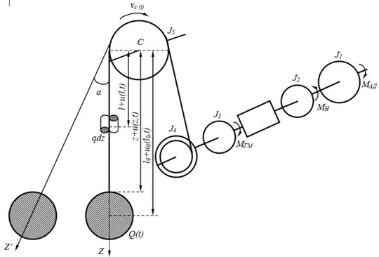
The resulting system for practical calculations should be simplified, taking into account the comments of researchers, and in this case, the pliability of the sections of traction elements between the winding drum and the pulley of the cargo boom can be neglected. I.e. the moment of inertia of the drum combine with the moment . This assumption will not lead to any noticeable distortion.
The under study towed object is mechanical system with variable weight and length, however, the relative rate of change of particles of this system is equal to zero. Therefore, the Lagrange equation of the II kind can be used for modeling [2-7]:
where is a generalized coordinate.
Eulerian coordinate of the arbitrary section of rope will be:
where – the absolute elongation of part of the cable with a length of .
Taking into account only the basic tone of vibrations, absolute lengthening of a rope can be represented in the form, where – unknown function of absolute elongation of a traction organ.
When determining the maximum dynamic loads of lifting devices, friction forces are not taken into account because they have a slight effect on the maximum amplitude of vibrations.
Taking in the Lagrange equation as the generalized coordinates the angles of rotation , , , , and the elongation function , we obtain a mathematical model describing the dynamic processes in the elastic elements of the investigated hydro-mechanical drive:
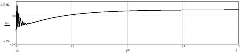
The transients of the considered hydraulic drive were simulated in the software package Mathcad. Modeling was carried out on the basis of the obtained equations. Fig. 3 shows the change of torque on the winding drum. The graph shows that the system adequately responds to changes in loading, unstable state during the transition process lasts a short period of time.
Fig. 3Change of torque on the winding drum obtained by modeling in Mathcad
2. Conclusions
As a result of the research, the following conclusions can be drawn:
1) To improve the operational reliability and efficiency of the drive system of the cable class of lifting devices, the use of a hydraulic drive sensitive to changes in loading is proposed. This is achieved by a smooth connection of the backup hydraulic motor in case of exceeding the rated load, which will ensure continuous stable operation of the equipment
2) This paper presents the development of a complex mathematical model of dynamic processes occurring in a complex hydro-mechanical system of ship’s deck lifting devices (Eqs. (1)-(15)) up to the moment of the second hydraulic motor starting and after its activation. In the obtained dependences, in contrast to the existing models of such devices, the cable is represented by a thread variable length. It also takes into account the change in the mass of the lifted load and, as a consequence, its Moment of inertia and hydrodynamic resistance.
3) The resulting system of differential equations allows to investigate longitudinal oscillations, to determine tension of viscoelastic rope at towing of an object and can be used at studying, designing and maintenance of such kind of drives of the lifting devices.
References
-
Ivanovskaya A. V., Bogatyreva E. V. The main aspects of the calculation of the power drive taking into account the variability of loading. Journal of Modern Fundamental and Applied Research, Vol. 25, Issue 2, 2017, p. 22-29.
-
2Ivanovskaya A. V., Popov V. V. Development of a mathematical model of the mechanical part of a hydraulic drive sensitive to changing loads. Proceedings of the 7th International Scientific Conference, 2018, p. 205-209.
-
Goroshko O. A., Savin G. N. Introduction to the Mechanics of Deformable One-Dimensional Bodies of Variable Length. Naukova Dumka, Kiev, 1971, p. 270.
-
Slepova L., Zhilenkov A. Approximating the solution of thermal conductivity problem for composite medium. IEEE Conference of Russian Young Researchers in Electrical and Electronic Engineering, 2019.
-
Babakov I. M. The Theory of Oscillations. Nauka, Moscow, 1976, p. 592.
-
Sokolov S., Zhilenkov A., Chernyi S., Nyrkov A., Mamunts D. dynamics models of synchronized piecewise linear discrete chaotic systems of high order. Symmetry, Vol. 11, Issue 2, 2019, p. 236.
-
Glebov N., Zhilenkov A., Chernyi S., Sokolov S. Process of the positioning complex modeling objects with elements of intellectual analysis. Procedia Computer Science, Vol. 150, 2019, p. 609-615.
-
Ivanovskaya A. V., Bogatyreva E. V., Klimenko N. P., Popov V. V., Sharatov A. S. The analysis of failures and an estimation of reliability of deck mechanisms in operation. Technical Service of Agro-Industrial, Forestry and Transport Complexes, Vol. 5, 2016, p. 101-108.
-
Bashurov B. P., Skiba A. N., Chebanov V. S. Functional Reliability and Control of the Technical Condition of Ship Supporting Mechanisms: A Training Manual. Admiral F.F. Ushakov, Novorossiysk, 2009, p. 192.
-
Popov V. V., Ivanovskaya A. V. Development of a laboratory installation for the study of a hydraulic drive sensitive to changing loads. Proceedings of the International Scientific and Practical Conference, St. Petersburg, 2018, p. 16-19.
Cited by
About this article

