Abstract
Wind turbine energy minimizes due to vibration of blade. In this research we focus on vibration suppression by using particle damping technique. Containers are used for fill the particles and mounted on the blade. As vibration of blade increases, it increases the movement of containers along with particles this brings particle to particle and particle to container wall collision takes place which results to energy loss. In this study we use four different positions for mounting containers, firstly on all four different positions we mount containers simultaneously and take three readings for three different ball sizes respectively, keeping 50 % fill constant in all readings. Then we reduce one container among four and take the readings. Repeat this procedure up to single container. Compare with damping results with without damping results and finding out optimum locations for mounting of dampers.
Highlights
- 7 mm particle size gives optimum conditions for damper location as compare to 5 mm
- 3 position mounting with 7 mm particles with 9 mm particles gives optimum conditions
- 2 position mount with 9 mm particles gives optimum conditions
1. Introduction
In wind energy power generation, if vibrations of the blade are high then it adversely effect on electricity generation [1]. Edgewise vibration and flapwise vibrations were the two main modes of vibration in blade [2]. Edgewise vibration is the main concern in this work. Structural vibration had been control by three methods namely active, semi active and passive control according to Dapeng [3]. Krenk [4] introduced active struts mounted near the blade root. Fitzgerald introduced edgewise vibration mitigation by using active tuned mass damper [5]. According to Box [6] active tendons was inserted inside blade for vibration control. Box [7] was introducing roller damper in blade. The new concept as tuned liquid column damper (TLCD) for blade vibration reduction, passive damping was used by Colwell [8] and Murtagh [9] in wind turbine tower for control of vibrations.
In this paper particle damping technique is used to check the effect of different parameters on 1 kW wind turbine blade for vibration suppression. Three parameters are used such as particle size variation, change in position and change in percentage fill. At this moment it is not possible to make pocket inside the blade for inserting balls. But for checking the effect we attach external container on blade.
2. Experimental set up
Electrodynamic shaker (EEV 060) having force rating of 600 Kgf is use for generating frequency in the range of 10 Hz to 2000 Hz and Acceleration is consider for the first two modes. We consider 1 Kw wind turbine blade for testing which is mounted at the root location and hermetically sealed type piezo electric accelerometer is mounted at the position of 600 mm randomly considering the maximum displacement location. Output of accelerometer is connected to single channel, digital vibration controller (EESC – 04), generating low electric signals. These electric signals amplify with power amplifier from the vibration controller to a proportionally high voltage and high current output. Acceleration range is kept as 8 g and frequency range up to 2000 Hz. Materials and different parameters are explained as follows.
2.1. Parameters for testing
2.1.1. Ball size
Three different particle sizes are used as 3 mm, 5 mm and 9 mm for effect of vibration suppression.
2.1.2. Container position on blade
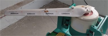
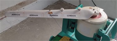
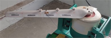
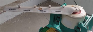
Total four positions taken for the testing as 300 mm, 600 mm, 900 mm and 1200 mm.
2.2. Materials
(a) Particle: Testing of particle is done by Wet Method: ALS:SOP:05-TM 503, REST by IS 228:2010 for particle damping having chemical composition of 0.010 % Mo, 0.050 % Ni, 0.98 % C, 0.33 % Mn, 0.25 % Si, 0.010 % S, 0.012 % P, 1.40 % Cr.
(b) Container: Container is made with Poly-propylene (PP) material, tested by method of ASTM D-792, D-297 and IS 13360.
(c) Blade: Glass fibre blade having length of 1525 mm.
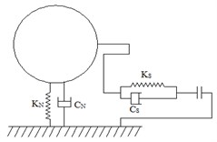
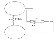
Fig. 1(a) and (b) shows spring mass diagram for ball-wall and ball-ball collisions, where, , , , are stiffness’s and damping constants.
Fig. 1a) Ball-wall spring mass diagram, b) ball-ball spring mass diagram
a)
b)
Fig. 2Block diagram of experimental set up
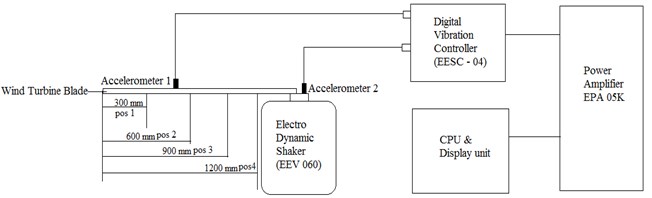
Fig. 3Actual diagram of experimental set up
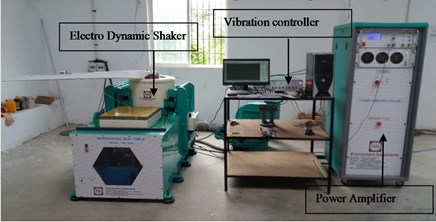
Fig. 2 shows block diagram and Fig. 3 shows Actual experimental set up. Fig. 4 shows four different mounting conditions of containers as single, 2 positions, 3 positions and 4 positions mounting.
Fig. 4Containers at different positions (single, two, three, four containers respectively)
3. Result and discussion
All results are plotted as acceleration in gravity (g) versus frequency (Hz) for without damping and with damping conditions.
Fig. 5Without damping
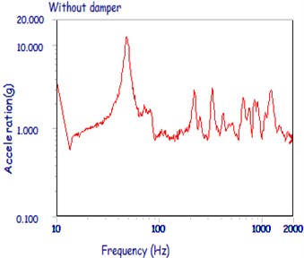
Fig. 6Four position damper, 5 mm ball, 50 % fill
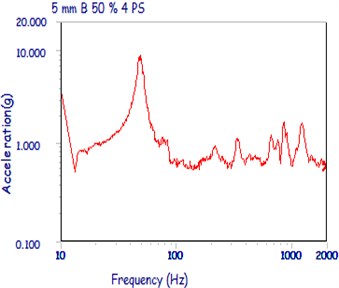
Fig. 7Four position damper, 7 mm ball, 50 % fill
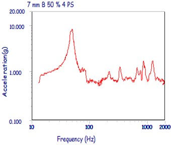
Fig. 8Four position damper, 9 mm ball, 50 % fill
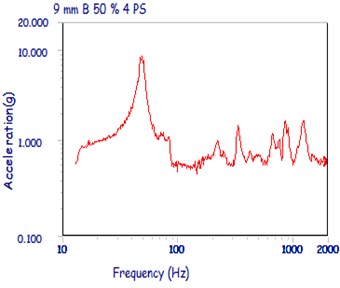
Fig. 5 show with damping results as 12.895 g and 2.753 g for 1st and 2nd modes respectively. All with damping results are compared with without damping and finding out the optical conditions for mounting dampers. All containers are fill with 50 % particles, and taking readings for three different ball sizes as 5 mm, 7 mm and 9 mm respectively.
Fig. 9Three position damper, 5 mm ball, 50 % fill
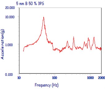
Fig. 10Three position damper, 7 mm ball, 50 % fill
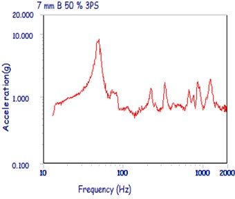
Fig. 11Three position damper, 9 mm ball, 50 % fill
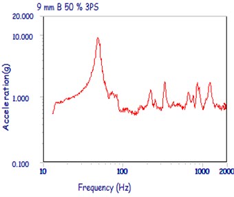
Fig. 12Two position damper, 5 mm ball, 50 % fill
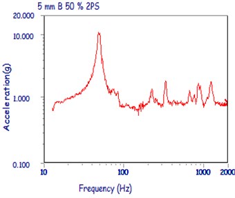
Fig. 13Two position damper, 7 mm ball, 50 % fill
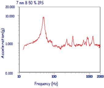
Fig. 14Two position damper, 9 mm ball, 50 % fill
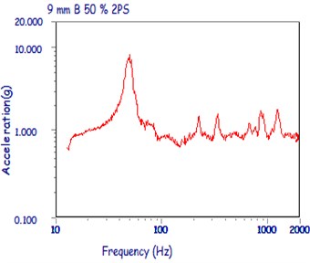
Table 1 gives results of containers mounting at 4 position, 3 position, 2 position, 1 position and without damping conditions. Fig. 6-8 shows graphs for 4 position mount, Figs. 9-11 gives graphs for 3 position mount , 5, 7 and 9 mm ball sizes graphs. Figs. 12-14 shows graphs for 2 position mount and Fig. 15-17 shows graphs for single position mount.
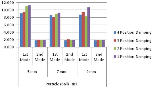
Table 1 shows that in 4 position mount 7 mm ball gives optimum results as 8.565 g and 1.830 g acceleration for 1st and 2nd modes. All results are compared with without damping results as in 1st mode 12.895 g is very large acceleration as compared to 4 position damping and in second mode 2.753 g is also high acceleration value. In 3 position and single position also 7 mm ball size gives optimum results. But, in case of 2 position mount 9 mm ball size gives optimum result as shown in Table 1. Same results are shown in cumulative result graph.
Table 1Testing results for different positions
Position of damper | Particle (Ball) size | |||||
5 mm | 7 mm | 9 mm | ||||
1st mode | 2nd mode | 1st mode | 2nd mode | 1st mode | 2nd mode | |
4 Position damping | 9.068 | 1.847 | 8.565 | 1.830 | 8.741 | 1.796 |
3 Position damping | 9.549 | 1.975 | 8.157 | 2.033 | 9.452 | 1.892 |
2 Position damping | 11.025 | 1.922 | 9.065 | 1.928 | 8.274 | 1.898 |
1 Position damping | 11.251 | 1.983 | 9.299 | 1.951 | 10.774 | 1.874 |
Without damping | 1st Mode: 12.895, 2nd Mode: 2.753 | |||||
Fig. 15Single position damper, 5 mm ball, 50 % fill
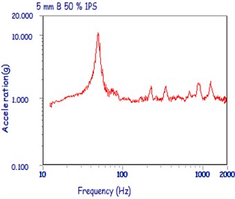
Fig. 16Single position damper, 7 mm ball, 50 % fill
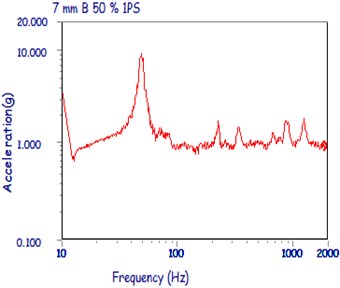
Fig. 17Single position damper, 9 mm ball, 50 % fill
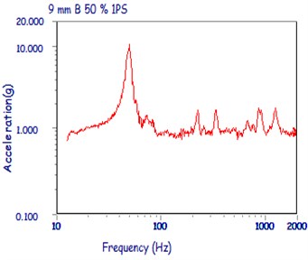
Fig. 18Cumulative results for all positions and all particle sizes
4. Conclusions
At 7 mm particle size we get optimum conditions for damper location as compare to 5 mm and 9 mm ball size. In overall results 3 position mounting with 7 mm particles and 2 position mount with 9 mm particles gives optimum conditions.
References
-
Mina Ghassempour, Giuseppe Failla Vibration mitigation in offshore wind turbines via tuned mass damper. Engineering Structures, Vol. 183, 2019, p. 610-636.
-
Thomsen K., Petersen J. T., Nim E., Øye S., Petersen B. A method for determination of damping for edgewise blade vibrations. Wind Energy, Vol. 3, Issue 4, 2000, p. 233-246.
-
Qiu Dapeng, Chen Jianyun Dynamic responses and damage forms analysis of underground large scale frame structures under oblique SV seismic waves. Soil Dynamics and Earthquake Engineering, Vol. 117, 2019, p. 216-220.
-
Krenk S., Svendsen M. N., Høgsberg J. Resonant vibration control of three-bladed wind turbine rotors. AIAA Journal, Vol. 50, Issue 1, 2012, p. 148-161.
-
Fitzgerald B., Basu B., Nielsen S. R. K. Active tuned mass dampers for control of in-plane vibrations of wind turbine blades. Structural Control and Health Monitoring, Vol. 20, Issue 12, 2013, p. 1377-1396.
-
George Box E. P., Norman Draper R. Empirical Model Building and Response Surfaces. John Wiley and Sons, New York, 1987.
-
George Box E. P., Norman Draper R. Response Surfaces, Mixtures, and Ridge Analysis. Second Edition, John Wiley and Sons, Hoboken, New Jersey, USA.
-
Colwell S., Basu B. Tuned liquid column dampers in offshore wind turbines for structural control. Engineering Structures, Vol. 31, Issue 2, 2009, p. 358-368.
-
Murtagh P. J., Ghosh A., Basu B., Broderick B. M. Passive control of wind turbine vibrations including blade/tower interaction and rotationally sampled turbulence. Wind Energy, Vol. 11, Issue 4, 2007, https://doi.org/10.1002/we.249.
About this article

