Abstract
Prestress concrete channel beam bridge is a new structure suitable for railway bridges. Due to its advantages under stress, construction and economy, channel beam has been widely used and developed rapidly in engineering construction. However, the concrete track bed plate of channel beam bridge has the characteristics of large transverse width and weight, the stress of inclined wall box girder, complicated construction process, difficult control of concrete crack, and high construction technical difficulty. Therefore, it is necessary to study the wide channel beam bridge. This paper carries out safety checking calculation on the support structure of Bailey beams of channel beam bridge. The results showed that the supporting structure can be considered to be safe. The relevant structural safety design can provide reference to similar projects.
Highlights
- 48 m channel beam bridge is first to build for double track railway
- Safety study was conducted for wide channel beam bridge
- Safety analysis of support structure is carried out based on finite element model
1. Introduction
Prestress concrete channel beam bridge is a new structure suitable for highway bridges, railway bridges and urban rail transit. Compare with the conventional t-beam bridge and box girder bridge, the channel beam can significantly reduce the height of the superstructure, increase the clearance under the bridge, reduce the height of the embankment, block the traffic noise and prevent the overturning of vehicles. It also has the characteristics of beautiful shape, convenient maintenance and good anti-seismic performance [1]. Due to its advantages under stress, construction and economy, channel beam has been widely used and developed rapidly in engineering construction.
According to the layout of track line, the channel beam bridge can be divided into single channel beam bridge and double channel beam bridge. Due to the deviation between the center line of the line and the central axis of the bridge deck, the structure biased load is obvious when the train is running on one side, and the influence of torque on the main beams on both sides cannot be ignored [2]. In addition, according to the main beam web form, channel beam can be divided into two categories: straight wall type and inclined wall type. The main girder of the straight wall type channel beam bridge adopts vertical web, and the web of the main girder of the inclined wall type channel beam bridge is inclined outwards [3]. By tilting the upper flange to the outside, the main beam spacing of slotted beam of inclined wall type is smaller than that of straight wall slotted beam, which reduces the transverse span of track bed plate [4]. Therefore, slotted beam of inclined wall type has relatively higher utilization rate of section space. Channel beam has become one of the most competitive structural forms in modern urban rail transit viaduct.
However, the concrete track bed plate of channel beam bridge has the characteristics of large transverse width and weight, the stress of inclined wall box girder, complicated construction process, difficult control of concrete crack, and high construction technical difficulty [5]. Especially in the combination of box girder and girder bed plate, the composite effect of bending, shear and torsion is obvious, and the combination of bed plate and girder web is easy to crack. Therefore, it is necessary to study the wide channel beam bridge.
Due to the 48 m channel beam bridge is first to build for double track railway, it is important to evaluate the safety performance of the bridge. In this paper, the safety analysis of the support structure is carried out based on the finite element model, and the conclusion can provide reference for similar engineering applications.
2. Bridge profile
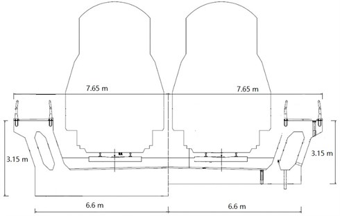
The channel beam bridge has the top width of 15.3 m, and the bottom width of 13.2 m. Standard section beam height 3.15 m. The minimum thickness of track bed plate is 70 cm, and the fulcrum is thickened to 130 cm. The side girder adopts inclined wall-type box section. The roof of box girder section is 1.95 m wide and 55 cm thick. Web thickness 32-45 cm. The longitudinal, transverse and vertical prestressing forces are set in the whole bridge, among which the longitudinal and transverse prestressing forces are made of low-relaxation steel strand with tensile strength of 1860 MPa, with a total of 35 beams in the whole bridge. The vertical prestress adopts PSB830 finished rolled steel bar with diameter of 25 mm, 240 in total. The bridge is cast-in-place construction by bracket, the cross sectional drawing is shown in Fig. 1.
Fig. 1Cross sectional drawing of bridge
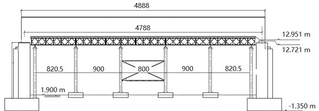
The support system of channel beam is composed of column, transverse distribution beam, longitudinal beam, square wood, and bamboo rubber plate bottom mould system, etc., as shown in Fig. 2. Beam support using 6 row of five columns, a total of 30 posts and 508 × 8 mm steel pipe with maximum length 10 m, which welding on caps and bar based on the embedded parts, respectively. The cross-bridge spacing is 2.0+2×3.15+2.0 m, and the consequent-bridge spacing is 8.205+3×9.0+8.205 m. The spiral pipe is decorated with two beams. Bailey beams are arranged on the beam with spacing of 120+5×45+5×120+5×45+120 cm. I14 distribution beams with a spacing of 75 cm were arranged on the Bailey beam, and 100×100 mm square wood was placed on the beam. Solid parts under the web were spaced 0.25 m, hollow parts 0.3 m, and groove bottom plates 0.45 m. The bottom mold is 18 mm bamboo rubber plate for the face.
Fig. 2Support system for bridge (Unit: mm)
3. Load and material parameters
According to the actual stress condition of the support, its load value is as follows:
(1) Weight of the structure consists of the weight of steel tube, Bailey beam, I-beam and other structures, which can be directly calculated according to the bulk weight of the material in Midas Civil.
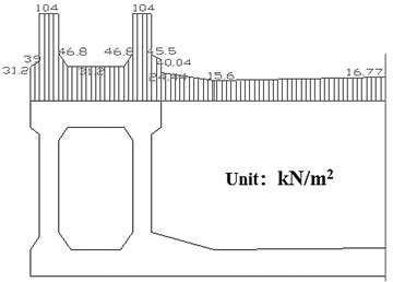
(2) Wet weight load of the main beam: the density of reinforced concrete is 26 kN/m3, according to the actual concrete pouring height on the formwork, and the load distribution of wet weight of concrete is calculated as shown in Fig. 3.
Fig. 3Wet weight load of the main beam
(3) Main beam formwork and support load is calculated according to uniformly distributed load, which is 2 kN /m2.
(4) Construction personnel and equipment load is 2 kN /m2.
(5) Load generated by vibrating concrete is 4 kN/m2.
(6) Concrete excess irrigation coefficient is 1.05.
Table 1 gives the mechanical properties parameters of the materials required for calculation.
Table 1Physical and mechanical properties of the materials
Materials | 16Mn Low alloy high strength structural steel | Q235 steel | Wood | |
Modulus of elasticity / MPa | 2.1×10⁵ | 2.06×10⁵ | 9×10³ | |
Allowable stress / MPa | Pull, press, bend | 210 | 140 | 12 |
Shear | 120 | 85 | 1.9 | |
Strength design value / MPa | Pull, press, bend | 310 | 215 | – |
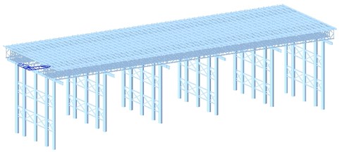
Midas Civil was used to establish the overall finite element model of the support system. The overall model has 7233 nodes and 12,590 elements, including 10310 beam elements and 2880 plate elements. The overall finite element model is shown in Fig. 4.
Fig. 4Finite element model
4. Results
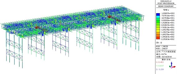
Fig. 5 shows the calculation results of the overall bending moment of support system. It can be seen that the maximum bending moment of the overall structure occurs on the double split I-beam supported by the second row from the outside to the inside, and the maximum bending moment is 229.3 kN·m.
Fig. 5Overall bending moment
Figs. 6 and 7 show the combined stress and shear stress distribution of the whole structure, respectively. The maximum combined stress of the overall structure is 200.3 MPa, which occurs at the lower chord of the most lateral column corresponding to the innermost Bailey beam under the big web. The maximum combined stress is less than the allowable stress of 16Mn of the Bailey beam, which meets the strength requirements. The maximum shear stress of the overall structure is 84.1 MPa, which occurs on the double-spined I-beam on the second row of support from the outside inside. Its value is less than the allowable shear stress of double-spined I-steel Q235, and the shear strength meets the requirements.
Fig. 6Combined stress of the overall structure
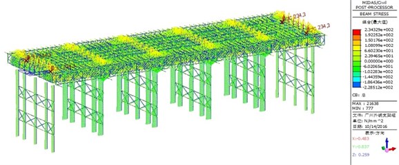
Fig. 7Shear stress of the overall structure
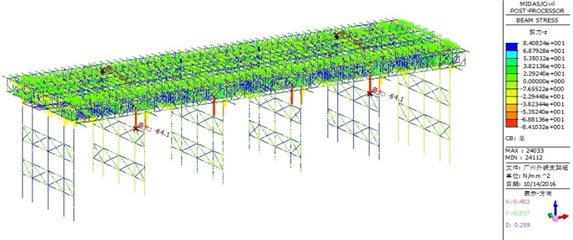
Fig. 8 shows the overall deformation diagram of the structure. The maximum vertical deformation is 8.14 mm downward, which occurs near the middle position of the side span. The maximum down warping value is less than the deformation limit /400 = 8205/400 = 20.5 mm, which meets the requirements of stiffness.
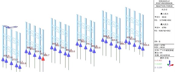
The calculated reaction force results of support system are shown in Fig. 9. The maximum support reaction force is 986.7 kN, which occurs on the second row of the outermost column.
Fig. 8Deformation of the overall structure
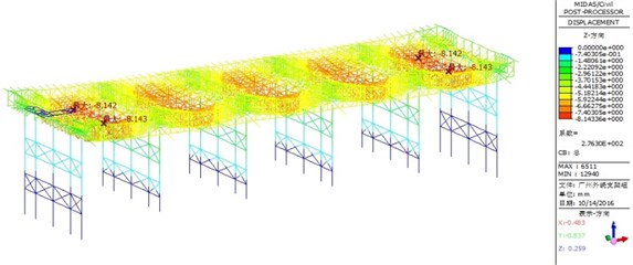
Fig. 9Reaction force
5. Conclusions
In order to ensure the safety of the support structure of a 48 m channel beam bridge, this paper carries out safety checking calculation on the support structure of Bailey beams of channel beam bridge. The software of Midas Civil was used to establish the finite element model of support system for bridge.
The maximum bending moment, the maximum combined stress, the maximum shear stress, and the overall deformation of the overall structure are calculated based on finite element model, and all of above are meet the requirement of safe, and the supporting structure can be considered to be safety. The relevant structural safety design can provide reference for similar projects.
References
-
Xia H., Zhang N. Dynamic analysis of railway bridge under high-speed trains. Computers and Structures, Vol. 83, 2005, p. 1891-1901.
-
Teng J. G., Yao J., Zhao Y. Distortional buckling of channel beam-columns. Thin-Walled Structures, Vol. 41, 2003, p. 595-617.
-
Razzaq Z., Prabhakaran R., Sirjani M. M. Load and resistance factor design (LRFD) approach for reinforced-plastic channel beam buckling. Composites Part B: Engineering, Vol. 27, 1996, p. 361-369.
-
Anapayan T., Mahendran M., Mahaarachchi D. Lateral distortional buckling tests of a new hollow flange channel beam. Thin-Walled Structures, Vol. 49, 2011, p. 13-25.
-
Torabian S., Zheng B., Schafer B. W. Experimental response of cold-formed steel lipped channel beam-columns. Thin-Walled Structures, Vol. 89, 2015, p. 152-168.
About this article

