Abstract
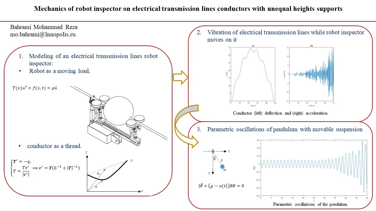
The aim of this paper is to create a mathematical model of the motion of robot inspector on electrical transmission lines conductors when the towers are not in one level i.e. when the tension through the conductor is not constant. In this model, we consider the electrical line as a thread with two supports at the ends with different elevations and the robot considered as a moving object on the thread. The obtained equation of motion has been solved by using the separating variables method. As the result, dangerous oscillations have been seen although the motion of the inspection robot on the line is steady. These vibrations may cause parametric vibration in the perpendicular plane of motion and can cause inertial load on the construction of the robot. To study this affect we consider the robot as a pendulum with movable suspension base. This article shows the possibility of a kind of parametric resonance.
Highlights
- Mathematical modeling of the motion of robot inspector on electrical transmission lines.
- Electrical line is considered as a thread with two supports at the ends with different elevations.
- Robot considered as a moving object on the thread.
- Oscillations have been seen although the motion of the inspection robot on the line is steady.
- These vibrations may cause parametric vibration in the perpendicular plane of motion.
1. Introduction
Power companies around the world utilize different method for inspection of electrical transmission lines to ensure consistency of energy supply to end users. According to budget and region regulation, the way of inspection will be defined. The most general way for inspection of overhead power lines is by human force utilizing vehicles or helicopters. In some countries have been used cable climbing robots for precise inspection [1, 2]. These type of robots with the help of all required instruments (sensors, cameras, etc.) can perform precise inspections.
The main aim of robotic inspection is to ensure the safety of personnel meanwhile having the precise inspection results to decrease the cost of unexpected accidents.
Design and construction of a fully smart robot for the task of inspecting is a challenge for engineers. There exist some factors that may affect the operation of such devices. Therefor it is needed to take them into in account in the first step of designing. Factors like; passing the obstacles (line equipment, tower mast, etc.), bad climates, etc.
Because of the variety of overhead power lines, different type of robot inspectors were designed and constructed [3-9]. One of the proposed designs for inspection of electrical lines is shown in Fig. 1. As shown in [10-14] extensive oscillations may be revealed even the motion of robot inspector on the line was steady. As shown in abovementioned works, these types of vibrations are dangerous and may have effect on the performance of the robots (as an example: the blurry image which affect the system of navigation of the robot inspector). According to abovementioned reasons, study of motion of robot inspector along the conductor and creating a mathematical model is required.
The main idea of this paper is to create a mathematical model to investigate the motion of the robot inspector along the conductor of electrical line transmission line when the tension in conductor is not constant. In this work, the conductor is considered as a thread while the robot is an object moving on it. The supports of the conductor (electrical towers) are assumed that are in different elevations. Mathematical modeling of the motion of the robot inspector on the electrical line is a great tool to study the stability during the operation of inspection robot on the electrical line.
Fig. 1Scheme of the electrical transmission robot inspector traveling on an electrical line [13]
![Scheme of the electrical transmission robot inspector traveling on an electrical line [13]](https://static-01.extrica.com/articles/21097/21097-img1.jpg)
2. Conductor as a thread
In [10-14] the electrical line is considered as a stretched string where supports are located in one level of elevation. This assumption is true, as proved in [10] since the tension in the conductor line in the whole length of the line is constant. But in these works that the supports (electrical towers) are in different elevation, we cannot consider the electrical line as a stretched string, since the tension varies during the length of the line and it depends on the sag as well.
Sag is the difference in level between the levels of support and the lowest level on the conductor. Calculating the sag and study its effect on the vibration of the electrical line are on the beyond of this article.
In this article, the conductor is considered as a thread when supports are at unequal heights and the robot inspector is considered as a moving object as shown in Fig. 2(b). In this section, a mathematical model for the thread when supports are at unequal heights has been created. Then mechanical tension in power line has been found. The thread only resists stretching (unlike a string with resistance to bending and torsion). The equations of mechanics of thread are presented, in [15-18]. We use the method explained in [10, 15].
The configuration of the thread is determined by the radius vector of the point on the material (Lagrangian) coordinate; before deformation (Fig. 2). The values in the initial state (before deformation) are indicated by zero.
Fig. 2Conductor as a thread
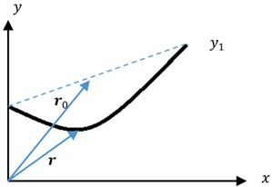
The material coordinate of the particle is preserved in . Usually considered as the arc coordinate in the initial state; then is the unit vector of the tangent (prime means differentiation with respect to ). Elongation is determined by the simplest formula . The tension force , where is the force in the initial state, is the tensile stiffness.
Since the wire only stretches from the load, we can assume that the initial state is unstressed 0. If the load is such that it can cause a shortening, then the initial state should be extended.
Given the equation of the balance of forces (with distributed load ), we have the following system [15]:
With boundary conditions , , where is the initial length of the conductor.
The nonlinear boundary problem posed for the ODE system is solved in Mathcad. ODE is presented in matrix form:
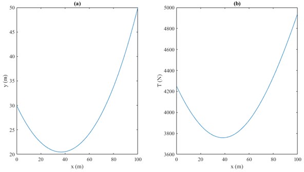
The calculations were carried out for an aluminum wire of radius 2.5 cm and 7e10 N/m2 ( is the Young’s modulus). The length and the coordinates of the fixed ends 100 m, 100 m, 30m, 50 m. Distributed loads are: , (linear weight). Tensile stiffness is . The calculated wire configuration is shown in Fig. 3(a).
The tension force is . The graph of this function is shown in Fig. 3(b).
Fig. 3Conductor a) configuration and b) tension
3. Vibration of electrical transmission lines while robot inspector moves on it
The deflection equation of the electrical line, , is given from [11]:
where is designated to the string tension force, denotes to the linear load (per unit length), is the density. Differentiation relative to the coordinate and time showed by prime and dot. The boundary and initial conditions are , .
The force concentrated at a point using delta function will be , where determines how concentrated force can move with the condition of , ,
The solution of Eq. (3) can be constructed by the method of separating variables as [10]. Approximate deflection of the conductor is , , where ( 1,…, ) is generalized coordinates of the system.
Defining delta function as one can write the expression for generalized coordinates of the system ( 1,…, ):
Rewriting the concentrated force as where and multiplying both sides of Eq. (3) by and integrating, we obtain ordinary differential equations (ODE) for :
where .
These ODEs are solved by the Duhamel integral under zero initial conditions we obtain the solution of Eq. (5):
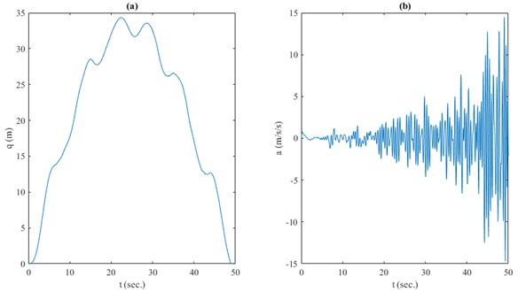
Fig. 4(a) and 4(b) show the deflection and acceleration of the conductor using from previous section and using 1 kN, 2 m/s and 5 kg/m for length and the coordinates of the fixed ends as in previous section. Although the motion of the robot inspector along the line is steady, but as shown in Fig. 4(a) vibrations appear in the vertical plane. Acceleration illustrated in Fig. 4(b) might cause inertial load on the robot structure.
Fig. 4Conductor a) deflection (m) and b) acceleration (m/s2) vs time (sec.)
4. Parametric oscillations of pendulum with movable suspension base
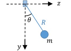
The consequence of these vibrations may also be parametric oscillations of the robot as a pendulum with movable suspension base (Fig. 5) [12].
Here, the equation of a pendulum has been used:
where is the angle of deflection as shown in Fig. 5, is the moment of inertia about the axis of rotation, is the distance from the center of mass to the base point. According to the definition, with the time varying , parametric resonance may appear. The parametric oscillations are more dangerous than the other type of oscillations.
Fig. 5Pendulum with a movable suspension base
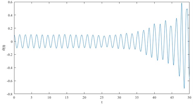
In this article since the excitation is not periodic, then we can say it is not the classical parametric resonance, but dangerous vibrations with increasing amplitude is feasible. This character can be investigated by mathematical modeling using Eq. (7) with initial conditions: and . is acceleration as shown in Fig. 4(b). Results of the numerical solution of Eq. (7) are obtained and shown in Fig. 6.
Fig. 6 shows the increase of oscillations which are limited only by the time of the process. Here, we chose the parameters of pendulum specifically in order to see this increase. This example shows that a kind of parametric resonance may occur.
Fig. 6Parametric oscillations of the pendulum
5. Conclusions
The goal of this paper is to investigate the motion of robot inspector on electrical transmission lines conductors when the tension in conductor is not constant, i.e. the towers height are unequal. The movement of robot inspector on the line has been modeled. In this model, the electrical line is considered as a thread when tension is not constant (with two unequal height supports at the ends) and the robot considered as a moving load on the thread. The obtained equation of motion has been solved by using the separating variables method. As the result, observed that oscillations occur even the motion of the robot on the electrical line is steady and may cause the parametric oscillation in the perpendicular plane of the motion. We investigated this effect by considering the robot as a pendulum with movable suspension base. Result shows the increase of oscillations. This example helps design engineers at early stage of design to prevent unwanted situations (e.g. parametric oscillations) by choosing the parameters of robot inspector.
References
-
Nayyerloo M. Cable-Climbing Robots for Power Transmission Lines Inspection. Mobile Robots – State of the Art in Land, Sea, Air, and Collaborative Missions, 2009.
-
Toussaint K., Pouliot N., Montambault S. Transmission line maintenance robots capable of crossing obstacles: State‐of‐the‐art review and challenges ahead. Journal of Field Robotics, Vol. 26, Issue 5, 2009, p. 477-499.
-
Aoshima S. I., Tsujimura T., Yabuta T. A wire mobile robot with multi-unit structure. IEEE/RSJ International Workshop on Intelligent Robots and Systems, The Autonomous Mobile Robots and Its Applications, 1989.
-
Sawada J., Kusumoto K., Maikawa Y., Munakata T., Ishikawa Y. A mobile robot for inspection of power transmission lines. IEEE Transactions on Power Delivery, Vol. 6, Issue 1, 1991, p. 309-315.
-
Higuchi M., Maeda Y., Tsutani S., Hagihara S. Development of a mobile inspection robot for power transmission lines. Journal of the Robotics Society of Japan, Vol. 9, Issue 4, 1991, p. 457-463.
-
Tsujimura T., Morimitsu T. Dynamics of mobile legs suspended from wire. Robotics and Autonomous Systems, Vol. 20, Issue 1, 1997, p. 85-98.
-
Montambault S., Pouliot N. Design and validation of a mobile robot for power line inspection and maintenance. 6th International Conference on Field and Service Robotics-FSR, 2007.
-
Debenest P., Guarnieri M., Takita K., Fukushima E., Shigeo H., Tamura K., Kimura A., Kubokawa H., Iwama N. Robot for inspection of transmission lines. IEEE International Conference on Robotics and Automation, 2008.
-
Bahrami M. R. A novel design of an electrical transmission line inspection machine. Advances in Mechanical Engineering, 2016, p. 67-73.
-
Eliseev V. V., Bahrami M. R. Diagnostic machine on power transmission lines: configuration and mechanical challenges. St. Petersburg Polytechnic University Journal, Vol. 214, 2015, p. 200-207.
-
Eliseev V. V., Bahrami M. R. Strength suspension of inspector robot on the electrical transmission line wire. Bulletin of Engineering, Vol. 6, 2016, p. 19-22.
-
Bahrami M. R. Mechanics of diagnostic machine on electrical transmission lines conductors. International Conference on Modern Trends in Manufacturing Technologies and Equipment, Vol. 224, 2018, p. 02021.
-
Bahrami M. R., Abed S. A. Mechanics of robot inspector on electrical transmission lines conductors: performance analysis of dynamic vibration absorber. Vibroengineering Procedia, Vol. 25, 2019, p. 60-64.
-
Bahrami M. R., Abed S. A. Mechanical challenges of electrical transmission lines inspection robot. IOP Conference Series: Materials Science and Engineering, 2019.
-
Eliseev V. V. Mechanics of Deformation of Rigid Body. St. Petersburg, Russia, 2006.
-
Tikhonov A. N., Samarsky A. A. Equations of Mathematical Physics. Science, Moscow, 1979.
-
Merkin D. R. Introduction to Thread Mechanics. Science, Moscow, 1981.
-
Svetlitsky V. A. Mechanics of Flexible Rods and Threads. Mechanical Engineering, Moscow, 1978.
Cited by
About this article

