Abstract
The aim of the paper is to study the effects of an accelerometer mass on natural frequency of a cantilever beam of AZ61 magnesium alloy. The fundamental natural frequency of the beam is determined experimentally using vibration analyzer OROS-34 for different location of accelerometer mass on the beam. Vibration in the beam is generated by a lightweight hand hammer. Analytical formulation is done to calculate modal properties of a mass loaded beam. Further, the problem is simulated using ANSYS and the simulated results are compared with the experimental and analytical results.
Highlights
- Experimental Investigation on natural frequency of a magnesium alloy cantilever beam with varying location of accelerometer mass
- Finite element simulation using ANSYS
- Analytical model of a beam in fixed - free condition with concentrated point mass
1. Introduction
The economical design of any structure leads to efficient use of its materials while high production of a component is possible due to high speeds of the machines. Thus the inclinations towards lightweight structures and highly efficient machines are responsible for creating resonant conditions during service of the structures and machines. It is essential to measure the vibration characteristics in regular manner to avoid any accident due to resonance. There are many authors (Srinath and Das [1], Ozkaya [2], Low [3], Mermertas and Erol [4], Oz and Ozkaya [5], Kotambkar [6], Caker and Sanliturk [7], Sadri et al. [8], Vladimir et al. [9], Kras and Gardonio [10]) who have used various methods to study the behaviour of vibrating structures and machines. Xu et al. [11] focused on the principles, methods and applications of intelligent vibration control in civil engineering structures. Hatter [12] used computational methods of vibration analysis for different mechanical systems. In most of the conditions, the mass of accelerometer is neglected but for vibration analysis of lightweight structures with accuracy, the accelerometer mass should also be considered. In this paper, the effects of accelerometer mass on natural frequency of a cantilever beam are studied analytically, numerically and experimentally. The simulated results by ANSYS are compared satisfactorily with the analytical and experimental results.
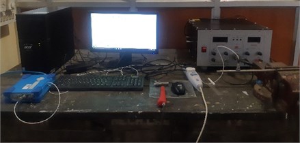
2. Experimental setup
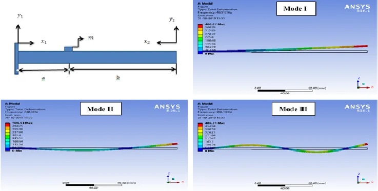
An experimental setup consists of a vibration analyzer (OROS-34), computer, a beam of AZ61 magnesium alloy, vice to fix one end of the beam and a hand hammer is used for investigation. The dimension of the beam is 250×10×4 in mm, mass of accelerometer is 12.95 gm. Young’s modulus () and material density of the beam are considered as 45 GPa and 1800 kg/m3 respectively. One end of the beam is fixed in vice and the length of the hanging portion of the beam is 240 mm. Accelerometer is mounted at desired place on the beam and the response signal generated after its initial excitation with the help of the hand hammer is used as the input for the vibration analyzer. This process is repeated for different locations on the beam and its natural frequency is obtained corresponding to each location in Mode I.
Fig. 1Experimental setup
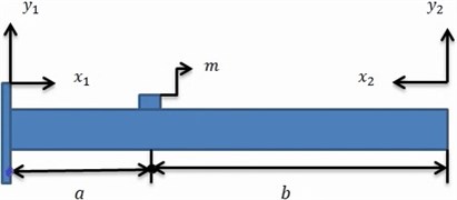
3. Analytical solution
An analytical model of beam in fixed-free condition (cantilever) with concentrated point mass (m) of accelerometer is considered. A dual frame of reference is used and the beam is divided into two parts from the mass location. Each part has four constants and therefore, there are total eight constants for the beam. Beam has eight constants but only four boundary conditions (slope and deflection are zero at fixed end whereas moment and shear force are taken as zero at free end) are available. Therefore, to solve the problem, additional four compatibility equations [3] are used.
Fig. 2Beam in fixed-free condition with accelerometer mass
The Euler-Bernoulli equation for free vibration of the beam is given by:
Using variable separable method, the solution can be written as:
The mode shape function is represent as:
where, .
The natural frequency can be written as:
The beam is divided in to two parts at the mass location; two coordinate systems are used at each end of beam:
where, at left end of the beam ) and at right hand ()
At the left hand of the beam is fixed, displacement field satisfies boundary conditions. Deflection ( and slope), can be written as:
At the right hand of the beam is free, displacement field satisfies boundary conditions. Moment () and shear force (), can be written as:
Four compatibility equations [3] are applied at the mass location.
Equation for displacement at the location of attached mass:
Equation for slope at the location of attached mass:
Equation for moment at the location of attached mass:
Equation for shear force at the location of attached mass:
Let us assume (Non-dimensional mass location parameter) and:
Combining Eqs. (10), (12), (14) and (16), the frequency equation can be found in determinant form as:
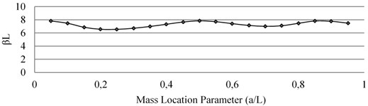
After solving the above determinant of Eq. (17) with the help of MATLAB, the values of at different locations ( ratios) on the beam are determined for Mode I, Mode II and Mode III. The corresponding natural frequencies are thus obtained by using Eq. (4). Table 1 shows that the natural frequency is sensitive to mass addition and its location in different modes. The effects of the accelerometer mass in Mode I, Mode II and Mode III of the vibrating cantilever beam are given in Fig. 3, Fig. 4 and Fig. 5 respectively where the variation in βL is shown with respect to non-dimensional location parameter () of the mass.
Table 1Effects of mass locations on first three bending modes
Sl. No. | ||||
Mode I | Mode II | Mode III | ||
1 | 0.05 | 1.87507 | 4.69180 | 7.82639 |
2 | 0.1 | 1.87470 | 4.66240 | 7.48033 |
3 | 0.15 | 1.87319 | 4.55980 | 6.86953 |
4 | 0.2 | 1.86934 | 4.37503 | 6.56548 |
5 | 0.25 | 1.86177 | 4.16797 | 6.55827 |
6 | 0.3 | 1.84913 | 3.99610 | 6.72475 |
7 | 0.35 | 1.83041 | 3.88078 | 6.99618 |
8 | 0.4 | 1.80522 | 3.82463 | 7.33186 |
9 | 0.45 | 1.77393 | 3.82531 | 7.67090 |
10 | 0.5 | 1.73751 | 3.87976 | 7.85383 |
11 | 0.55 | 1.69730 | 3.98526 | 7.71791 |
12 | 0.6 | 1.65463 | 4.13793 | 7.42023 |
13 | 0.65 | 1.61071 | 4.32736 | 7.15026 |
14 | 0.7 | 1.56646 | 4.52377 | 7.01323 |
15 | 0.75 | 1.52258 | 4.66458 | 7.10872 |
16 | 0.8 | 1.47954 | 4.68718 | 7.47536 |
17 | 0.85 | 1.43765 | 4.59606 | 7.82653 |
18 | 0.9 | 1.39711 | 4.43830 | 7.78095 |
19 | 0.95 | 1.35803 | 4.25216 | 7.49919 |
Fig. 3Effect of mass loading on natural frequency of Mode I
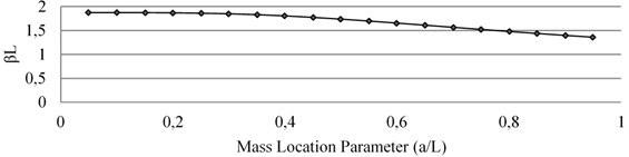
Fig. 4Effect of mass loading on natural frequency of Mode II
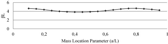
Fig. 5Effect of mass loading on natural frequency of Mode III
4. Finite element simulation using ANSYS
The finite element analysis simulation is done by modal analysis module of ANSYS workbench 16.1. At first, a 3D model of rectangular cross-section beam having dimension 240×10×4 in mm with attached point mass at desired location is developed in design modeler of the ANSYS software. This point mass is acting as the accelerometer mass. The model is now encastred at one end to act as a cantilever and meshing is done with the element type Hex20. The total number of elements and nodes are 1200 and 7605 respectively. The natural frequency of beam model is obtained from the software. The simulated results of natural frequencies in ANSYS at different locations are given in Table 2. For analysis, the linear vibration is considered. However, on moving the accelerometer from fixed end to free end, deflection in the beam increases which arises its increased geometrical non-linearity. This creates some error between experimental and other results.
Table 2Natural frequencies in Mode I obtained from analytical, numerical, experimental analyses
Sl. No. | Natural frequency (Hz) | |||
Analytical | ANSYS Simulation | Experimental | ||
1 | 0.05 | 55.699 | 56.247 | 52 |
2 | 0.1 | 55.678 | 56.225 | 52 |
3 | 0.15 | 55.588 | 56.135 | 52 |
4 | 0.2 | 55.359 | 55.907 | 51 |
5 | 0.25 | 55.000 | 55.459 | 50 |
6 | 0.3 | 54.169 | 54.712 | 48 |
7 | 0.35 | 53.077 | 53.613 | 47 |
8 | 0.4 | 51.627 | 52.150 | 45 |
9 | 0.45 | 49.853 | 50.358 | 42 |
10 | 0.5 | 47.827 | 48.312 | 41 |
11 | 0.55 | 45.638 | 46.099 | 39 |
12 | 0.6 | 43.373 | 43.808 | 36 |
13 | 0.65 | 41.101 | 41.510 | 34 |
14 | 0.7 | 38.873 | 39.257 | 31 |
15 | 0.75 | 36.726 | 37.100 | 30 |
16 | 0.8 | 34.679 | 35.014 | 28 |
17 | 0.85 | 32.743 | 33.055 | 26 |
18 | 0.9 | 30.922 | 31.215 | 25 |
19 | 0.95 | 29.217 | 29.490 | 23 |
5. Conclusions
From the analysis, it is clear that natural frequency of beam is more sensitive to mass attachment and its position. The fall in natural frequency in different modes is found maximum when the mass attachment is at the antinode. The frequency is not affected when the mass attachment is at the node. The results obtained from finite element simulation (ANSYS) are much closed to the analytical results while some deviation from the experimental results is due to geometrical non-linearity in the beam subjected to the mass attachment.
References
-
Srinath L. S., Das Y. C. Vibration of beams carrying mass. Journal of Applied Mechanics, Transactions of the ASME, Series E, Vol. 34, Issue 3, 1967, p. 784-785.
-
Özkaya E. Non-linear transverse vibrations of a simply supported beam carrying concentrated masses. Journal of Sound and Vibration, Vol. 257, Issue 3, 2002, p. 413-424.
-
Low K. H. A comparative study of the eigenvalue solutions for mass-loaded beams under classical boundary conditions. International Journal of Mechanical Sciences, Vol. 43, 2001, p. 237-244.
-
Mermertas V., Erol H. Effect of mass attachment on the free vibration of cracked beam. 8th International Congress on Sound and Vibration, Hong Kong, China, 2001, p. 2803-2810.
-
Öz H. R., Özkaya E. Natural frequencies of beam-mass systems in the transverse motion for different end conditions. Mathematical and Computational Application, Vol. 10, Issue 3, 2005, p. 369-367.
-
Kotambkar M. S. Effect of mass attachment on natural frequency of free-free beam. International Journal of Advanced Engineering Research and Studies, 2014, p. 102-105.
-
Cakar O., Sanliturk K. Y. Elimination of transducer mass loading effects from frequency response functions. Mechanical Systems and Signal Processing, Vol. 19, 2005, p. 87-104.
-
Sadri M., Lu T., Steenbergen M. Railway track degradation: The contribution of a spatially variant support stiffness - Global variation. Journal of Sound and Vibration, Vol. 464, 2020, p. 114992.
-
Vladimir S., Marko D. P., Dunja M. Nonlinear vibrations of a coupled beam-arch bridge system. Journal of Sound and Vibration, Vol. 464, 2020, p. 115000.
-
Kras A., Gardonio P. Active vibration control unit with a flywheel inertial actuator. Journal of Sound and Vibration, Vol. 464, 2020, p. 114987.
-
Xu Z.-D., Zhu J.-T., Guo Y.-Q., Xu F.-H. Intelligent Vibration Control in Civil Engineering Structures. Zhejiang University Press, 2015.
-
Hatter D. J. Matrix Computer Methods of Vibration Analysis. London Butterworths Press, London, 1973.
Cited by
About this article

