Abstract
In order to improve the efficiency of designing and analyzing a mortar base plate, parametric technology has been applied to the design and analysis of the base plate. By conducting characteristic analysis of the base plate, critical design parameters extracted have been driven as characteristics to perform secondary development on UG, so that the base plate could be automatically modeled in three dimensions. Meanwhile, Python has also been applied in the secondary development of Abaqus, so as to realize the automatic finite element modeling of the base plate. After conducting parametric analysis on the model established, sensitivities of design variables of the base plate have been analyzed using an approximate model in combination with the sample designed by the optimal Latin hypercube approach. Moreover, parametric optimization carrying out on results of sensitivity analysis could give feedback to parametric design for guiding parameter values of design variables to improve the design quality
1. Introduction
As the base plate is an integral part of the mortar, the rationality of the structure of the base plate has a significant influence on the shooting precision and stability of the mortar [1]. The base plate should be repeatedly tested and modified in the design stage before reaching the specific requirements, resulting in problems such as high research and development costs and long design cycles. The parametric technology is the best choice for improving the design and analysis efficiency. Specifically, parametric design is to restrain the sequence of structural dimensions in geometry with various parameters. In order to reach a new target geometry, means are provided for the variability, the reusability, and the parallel design of a product model [2]. Parametric analysis is a digital rapid analysis method based on the parametric technology, which can simplify analysis and improve the pre-processing efficiency of finite element analysis through automatically analyzing the model with relevant software [3].
The parametric technology has been utilized to design and analyze base plates in this paper. By conducting a characteristic analysis of the base plate, critical design parameters extracted have been driven as characteristics to perform secondary development on UG, so that the base plate could be automatically modeled in three dimensions. Meanwhile, Python has been applied in the secondary development of Abaqus, so as to realize the automatic finite element modeling of the base plate. By processing the model established, sensitivities of design variables of the base plate have been analyzed using an approximate model in combination with the sample designed by the optimal Latin hypercube approach. After optimizing results of sensitivity in a parametric way, optimized results could give feedback to parametric design for guiding parameter values of design variables to improve the design quality. The study method is shown in Fig. 1.
2. Parametric design of the base plate
2.1. Characteristic analysis of the base plate
A base plate of a mortar with the caliber of 120 mm is studied in this paper, which is a trapezoidal pyramid structure combining the advantages of the arched base plate and the trapezoidal base plate. Such structure has been mostly applied in active mortars worldwide [4]. It's mainly comprised of main metal plate, cone-shaped basin, stationary joint, wrapped rib, stud (inner), reinforcing rib and spade, as shown in Fig. 2.
Fig. 1Study method
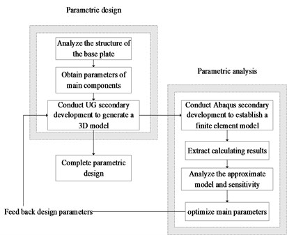
Fig. 2Structure diagram of the base plate
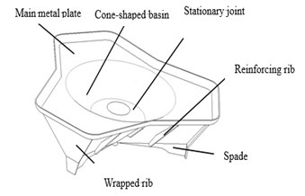
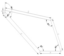
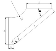
As the base plate is composed of three identical components that are characterized by central symmetry at 120°. Each component can be decomposed by structural characteristics and appropriately simplified into five basic parts including main metal plate, stud, stationary joint, wrapped rib, and spade. The two-dimensional diagram of each component is shown in Fig. 3. Moreover, there is an intermediate region seamed by the formation of main metal plate and stationary joints in the cone-shaped basin.
Fig. 3Two-dimensional diagram of main components of the base plate
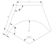
a) Main metal plate
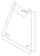
b) Wrapped rib
c) Stud
d) Stationary joint
2.2. Parametric design of the base plate
UG secondary development tools, such as UG/ Open MenuScript, UG/ Open UIStyler, UG/ Open API, and UG/ Open Grip, etc. are adopted to call the VC+ + program for implementing the parametric design of the base plate [5]. The basic flow of the parametric design of the base plate is presented in Fig. 4.
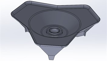
To be specific, MenuScript is a special module for UG to provide a customized menus; UIStyler is for generating different dialog boxes combining basic controls in the dialog box; API is an interface between UG and external applications; GRIP language is an engineer-oriented language which can implement various interacting operations with UG with the GRIP program.Parametric design is utilized to obtain a preliminary three-dimensional geometric model of a certain mortar base plate, as shown in Fig. 5.
Fig. 4Parametric design flow of the base plate
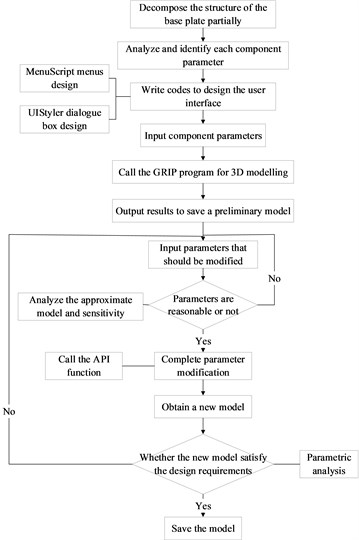
Fig. 5Geometric model of the base plate
2.3. Parametric analysis of the base plate
First and foremost, problem types to be simulated are modeled and generated into an input file. All operating commands are recorded by ABAQUS in the rpy file with Python scripts. And then, codes for the secondary development can be formed with simple modifications by using notepad++ to open the rpy file. A results file can be formed after the calculation. Next, accessing the results database with Python scripts can control, read and write the results file. Followed by that, data to be process are obtained by quoting object variables or using data objects in accordance with the actual problem and the storage path of data. Finally, results of data processed with proper are outputted in the form of a nephogram or a curve, contributing to subsequent analysis and view [6]. The call relationship between program modules of the system is presented in Fig. 6.
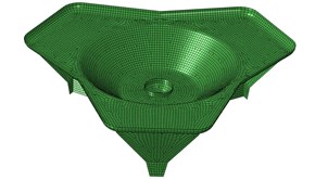
Numerical simulation is performed with the hard surface floor as the using environment at the elevation of 70° [7]. The bottom of the spade is set as a rigid restraint for shooting. The pressure curve of the mortar base with the caliber of 120 mm is applied to the spherical surface of the stationary joints. Dynamic Explicit is adopted for analyzing. The unit type is set as C3D10M, and models are made of titanium alloy. The finite element model established is shown in Fig. 7. The thicknesses of main metal plate , cone-shaped basin , stud , wrapped rib , and stationary joint are input as parameters with value ranges shown in Table 1.
Table 1The value range of parameters
Parameters | |||||
Lower limit / mm | 1 | 1 | 5 | 1 | 5 |
Upper limit / mm | 10 | 10 | 20 | 10 | 20 |
After setting simulation resources and paths, submit job to generate an input file (.inp). And input files are submitted to the ABAQUS/Standard solver for numerical operation via the background scripting. On the premise of completing analysis, open the result data file to access steps object below odb. Meanwhile, search for and extract the maximum stress Smax and the maximum displacement Umax in each analysis step and frame.
Fig. 6Call between program modules
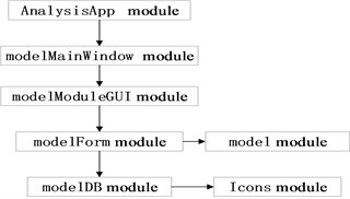
Fig. 7The finite element model of the base plate
3. Sensitivity analysis of parameters
3.1. Approximate model
Sensitivity analyses of designed parameters of the base plate are completed with the approximate model, so as to obtain the influence of the thickness parameters of each component in the parametric design on the maximum stress and the maximum displacement . RSM (response surface model) of is selected as the approximate model in this paper. The second-order RSM can be expressed as Eq. (1) [8]:
where, is the approximate value of the response surface; , is the design variable, is the number of design variables, , , , are undetermined coefficients of the constant term, the monomial term, the quadratic term, and the cross term, respectively. The multiple correlation coefficient is adopted to predict the fitting precision of RSM.
3.2. Parametric analysis of sensitivity
The finite element modeling and post-processing of parameterization are implemented automatically to extract results of finite element calculation using Python on the parametric analysis system established. And data are processed with Python to obtain the value of the objective function and return it to Isight for optimized analysis. After calling the file, modified files are firstly ranked according to the sequence of operation time and gathered in a test flow. Sample points are filtered within the feasible domain of design variables with the optimal Latin hypercube sampling approach. Secondly, variables in the intermediate link of the 100 sets of samples are automatically calculated by a computer and provided to the downstream is module for real-time parameter modification. Finally, the modified *.py is submitted to the Simcode module for operation, while the corresponding results obtained by the operation are read by the is module. In this way, the response values obtained are the maximum stress and the maximum displacement .
Regarding the maximum stress, has the greatest influence, indicating that the thickness of the stationary joint is the most influential part over the maximum stress on the base plate. Regarding the maximum displacement, has the greatest influence, indicating that the thickness of the main metal plate is the most influential part. By conducting sensitivity analysis on the parameters, providing feedback of optimized parameters to the parametric modelling of the base plate can help optimize the structural design of the base plate.
4. Parameter optimization of the base plate
4.1. Establishment of the parameter optimization model
Based on the above analysis, and in the base plates are optimized to ensure the establishment of a reasonable base plate model. Parametric optimization is aimed at searching for optimal parameters, so that calculated results can satisfy the following objective Eq. (2) [9]:
where, represents the mass of the base plate; and present the maximum stresses of the base plate before and after optimizing, respectively; and show the maximum displacement of the base plate before and after optimizing, respectively; and are the upper and lower limits of the value , respectively; and are the upper and lower limits of the value , respectively.
4.2. Optimizing results
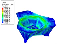
The stress nephogram and the displacement nephogram of the base plate before and after optimization are shown in Fig. 8 and Fig. 9, respectively. The thickness of the main metal plate and the stationary joint of the base plate, the mass of the base plate, the maximum stress and the maximum displacement are compared in Table 2.
Table 2Comparison of the base plate before and after optimizing
Category | / mm | / mm | Mass / kg | Max. stress/ MPa | Max. displacement/ mm |
Before optimizing | 8 | 8 | 61 | 322.3 | 4.271 |
After optimizing | 6.5 | 7.5 | 58.5 | 320.3 | 4.223 |
Decrease rate | 18.75 % | 6.25 % | 4.1 % | 0.62 % | 1.12 % |
Fig. 8Stress nephogram
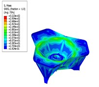
a) Before optimizing
b) After optimizing
Based on the analysis, it can be seen from the analysis that the maximum stress and the maximum displacement of the base plate are decreased after optimizing in comparison to that before optimizing, satisfying the design requirements. What’s more, the total mass of the base plate after optimizing is lower than that before optimizing, achieving the purpose of optimized design. And, the optimal values of and feed back to the parametric design system studied previously, which can effectively enhance the design quality and efficiency of the base plate model at the initial design stage.
Fig. 9Displacement nephogram
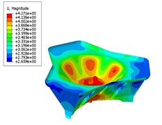
a) Before optimizing
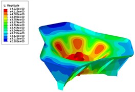
b) After optimizing
5. Conclusions
In this paper, parametric design and parametric analysis are applied to the design of the mortar base plate for the first time, and the following conclusions are given:
1) Critical design parameters extracted have been promoted as characteristics to perform secondary development on UG on the basis of conducting characteristic analysis of the base plate, so that the three-dimensional automatic modelling of the base plate can be implemented to enhance the design efficiency.
2) Meanwhile, applying Python into the secondary development of Abaqus can achieve the automatic finite element modeling and result extraction of the base plate.
3) Results obtained by parametric optimization is performed by sensitivity analysis, and which could give feedback to improve the design quality. It’s innovative in the parametric design of the base plate.
References
-
Tang Z. Mortar Design. Weapons Industry Press, 1994.
-
Meng X., Xu Y. Research on parametric design. Journal of Computer-Aided Design and Computer Graphics, Vol. 14, Issue 11, 2002, p. 1086-1090.
-
Lin Y., Ni Z., Liu X., et al. Research on digital fast analysis method based on parametric technology. Machinery Design and Manufacturing Engineering, Vol. 3, 2017, p. 8-53.
-
Wang X., Ge J., Yang G., et al. Lightweight design of mortar base plate. Journal of Gun Launch and Control, Vol. 39, Issue 4, 2018, p. 56-61.
-
Lu H., Liu X. Research and application of secondary development of UG software. Electronic Technology and Software Engineering, Vol. 149, Issue 3, 2019, p. 49.
-
Ma C. H. Research on Framework Design Platform Based on ABAQUS Secondary Development. Xi’an University of Architecture and Technology, 2018.
-
Zhou Z., Bu H., He Y. Analysis of the enthalpy-soil coupled launch dynamics of mortars. Journal of Ordnance Equipment, Vol. 37, Issue 2, 2016, p. 18-21.
-
Wang L., Yang G., Xiao H., et al. Interval optimization for structural dynamic responses of an artillery system under uncertainty. Engineering Optimization, 2019, https://doi.org/10.1080/0305215X.2019.1590563.
-
Hong Q. Theoretical basis and engineering application of OptiStruct and HyperStudy. Mechanical Industry Press, 2013, p. 158-196.
About this article

