Abstract
To solve the problem of main noise sources of motorcycles running at high speed, especially restoring the free sound field information of the target sound source in the non-free sound field, direct separation method with single holographic surface is proposed. According to the transfer function relationship between the theoretical and the measured sound pressure on the holographic surface based on the wave superposition algorithm, the individual radiation information of the target sound source in the coherent sound field is obtained. Through numerical simulation, it is found that the method could effectively separate the coherent sources. The radiation sound of motorcycles engine speed at 6000 r/min is measured, and the results show that the direct sound field separation method can effectively separate the coherent sound sources and intake noise radiate the higher pressure amplitude.
Highlights
- Separation method with single surface based on equivalent source method
- Souces identification with beamforming method
- Sources identication and separation for motorcylce coherent sound sources
1. Introduction
Near-field acoustic holography (NAH) is a spatial sound field visualization technology. The holographic surface is used to measure the pressure or particle velocity, through a series of sound field transformations, then the reconstruction and prediction of the three-dimensional sound field can be realized [1].
In order to eliminate the influence of background noise, the sound field separation method based on NAH technology has been developed. The spatial Fourier transform method [2] and the statistical optimal near-field acoustic holography (SONAH) are limited by the influence of the shape of the measurement surface [3, 4]. The boundary element (BEM) method has the problem of dealing with singular values and lower computational efficiency [5]. Mingsia et al. [6] studied the singular value problem based on linear interpolation optimization algorithm, and analyze the plane and spherical piston source through the numerical simulation. The equivalent source (ESM) method significantly improves the calculation efficiency and accuracy, because it is not limited by the size and shape of the vibrating body and there is no problem of processing singular values in calculation [7]. At the same time, due to the direct separation of the sound field in the spatial domain, the separation result can avoid the influence of the error caused by the window effect in the wave number domain with traditional separation method [8].
The main idea based on the ESM sound field separation method is to arrange some equivalent sources inside the vibrating body, and superimpose the sound fields of these equivalent source radiations instead of the sound field radiated by the vibrating body. At present, there are two main types of sound field separation technology input. One is to measure the sound pressure or particle vibration velocity of two measuring surfaces as input value [9, 10]; the other is to use single-sided sound pressure and particle vibration velocity as input value [11, 12]. Braikia et al. [13] compared the single-sided sound pressure and vibration speed with double-sided sound pressure measurement for the reverberation sound field of small space. Song [14] proposed a method of sound field separation based on spherical harmonic function. The effectiveness of the separation of spherical and aspheric coherent sound sources is verified by numerical simulation and experiments. Mingsia et al. [15] proposed a random array for noise source identification. The simulated recombination sensor is used to optimize the configuration distribution, and then use the beamforming positioning sound source to expand the sound field separation into an underdetermined problem and solve it by using the compressed sensing technology.
In the present paper, the sound pressure of the sound field measured by the single holographic surface is taken as input to separate the sound pressure of target source, and the coherent sound source of a certain motorcycle is separated to determine the main noise source through beamforming source localization.
2. Methodology
The basic idea of wave superposition method is to use the linear superposition of sound fields produced by a set of simple source to replace the actual sound field:
where is the pressure at , in sound field, , is the density of the medium, is sound velocity, is wave number, is the matrix of equivalent strengths at inside the radiator, and is the transfer matrix from the virtual source to arbitrary surface in the sound field.
Pressure on holographic surface could be measured, then the is calculated as:
where is generalized inverse of . When , the can be obtained by solving a least-norm optimal solution:
here, the superscript “” is conjugate transpose, is the regularization parameter chose by -curve, and is the identity matrix.
Therefore, the complex pressure on any surface can be determined from the basic formula of wave superposition.
For the coherent sources in sound field, the radiation information of target source could be obtained by method of sound field separation. In order to reduce the number of measuring points and improve calculation efficiency, the sound field separation with single surface based on wave superposition is used.
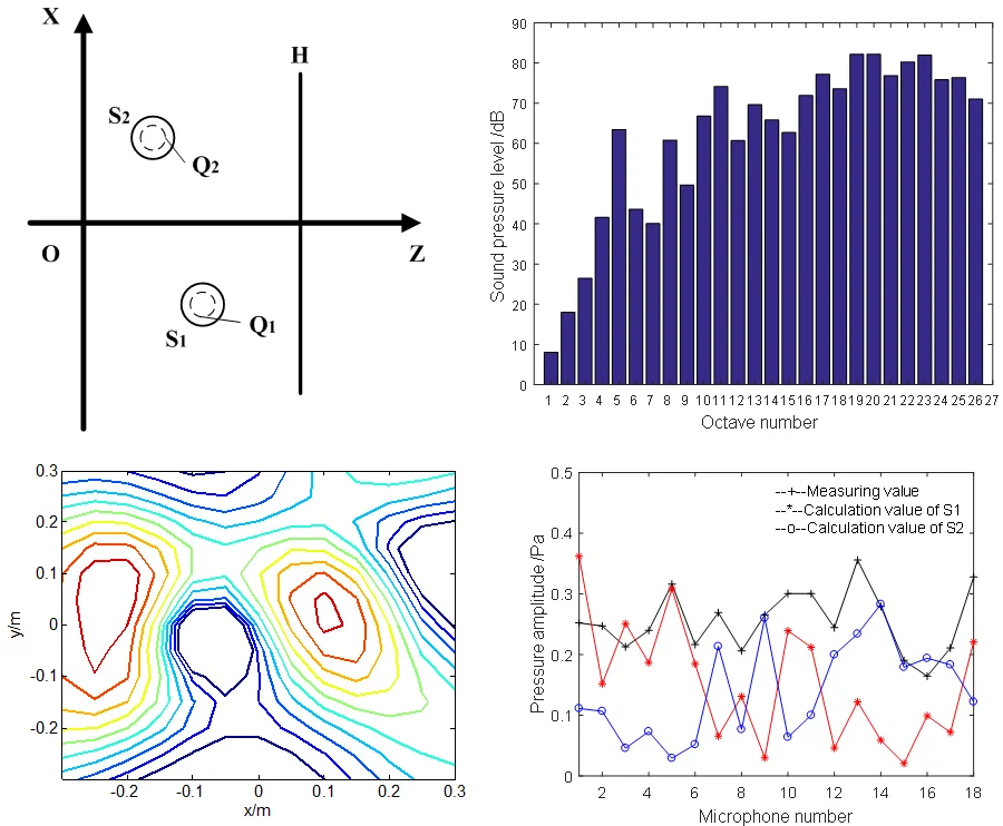
Fig. 1 is a schematic diagram of the position. During actual measurement, the complex pressure on holographic surface can be expressed as:
here, and are the theoretical value on holographic surface radiated by sources and , respectively, and is the error.
Assuming that the error is all from , then there is:
where is the pressure including error radiated from .
Similarly, could also be expressed as:
Thus, the complex pressure on holographic surface could be expressed as:
According to the principle of wave superposition, the theoretical value radiated by source could be calculated by the value including error as follows:
Based on the relationship between Eq. (9) and (10), the Eq. (7) and (8) can be derived to the follows:
can be solved by the above formula, as Eq. (13):
In summary, the formula of sound field separation with single surface is solved.
Fig. 1Schematic diagram of the position
3. Simulations
A series of simulations are performed according to the position lay out of Fig. 1. There, the holographic surface shows a 6×6 element microphone array with 7 cm grid spacing, and its distance to the origin is 0.1 m. The coordinate of and in Cartesian coordinate system are (–0.15, 0, 0.02) and (0.15, 0, 0) m, respectively, and the equivalent sources are placed inside the source according to the equal grid spherical division with 112 points. The SNR is set to 30 dB.
In addition, the error calculation formula in the process of sound field separation is expressed as:
here, and are the truth value and calculation value of pressure on holographic surface, respectively, and is the average error. The smaller the is, the smaller the error.
The numerical simulation of coherent sources is carried out with frequency at 1000 Hz.
Through numerical simulation, it can be found that this sound field separation method can accurately separate the sound pressure of the target sound source with fewer measuring points on single holographic surface.
Fig. 2Sound pressure on holographic surface: a) the sound pressure of coherent sources, b) theoretical sound pressure of target source, c) calculated sound pressure of target source, d) comparison of theoretical and calculated values on the xoz plane
a)
b)
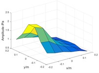
c)
d)
4. Experiment
4.1. Speaker experiment
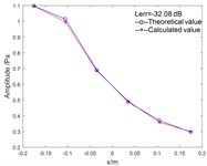
The measuring instrument used in the experiment is the 18-channel wheel type array of Brüel & Kjær and the rest of the placement was the same as the first simulation. Two speakers were as the coherent sound sources. The theoretical value was measured by target speaker, and the calculated value was separated by measured value radiated from the coherent sound sources.
Fig. 3 shows the amplitude and phase of measurement values and calculated value on the holographic surface. It indicates that the calculated value of target source is close to the measured value, indicating that the algorithm is effective. In Fig. 5(b), the initial phase are all set to 0 rad/s for convenience of comparison, and the phase difference on No. 18 sensor is large, but it is close to 2, that is, the error is small.
Fig. 3Experimental result: a) sound pressure amplitude comparison chart; b) phase comparison chart
a)

b)
4.2. Motorcycle experiment
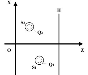
The speed of the motorcycle engine is 6000 r/min, and the microphone array is placed in the front part of the motorcycle. The distance between the array and the motorcycle is 20 cm. The array center and engine have common , direction coordinates in the three-dimensional coordinate system. The experimental data was processed according to the A-weighted 1/3 octave filter to obtain a corrected sound pressure level map as shown in Fig. 4.
From Fig. 4, there is a higher sound pressure level at the numbers 19, 20 and 23. The center frequencies corresponding to them are 1250 Hz, 1600 Hz and 3150 Hz, respectively. Then, we mainly analyze these frequencies.
In NAH technique, it needs amplitude and phase of pressure to calculate data. Through the multi-channel data acquisition at the same time, the amplitude could be obtained by self-spectrum. Taking the first microphone as a reference point, the relative phase of each measured point is calculated.
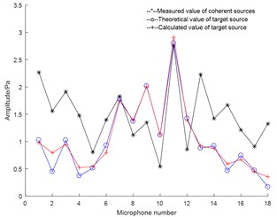
Before sound field separation, it is necessary to use the generalized inverse algorithm of beamforming to identify the position of the noise radiated by the motorcycle, and it is found that the coherent sources are only existed in 1600 Hz as Fig. 5.
In Fig. 5, the coordinates of the center of the two coherent sound sources on the plane are approximately S1 (–0.2, 0.05) m and S2 (0.1, 0) m. The position of sources S1 and S2 are roughly at the intake of the motorcycle and at the motorcycle engine, separately. After determining the position of the coherent sources, the direct sound field separation method of the single holographic surface is used to separate the coherent sources based on ESM, and the data is reconstructed on the holographic surface.
Fig. 4A weighted 1/3 octave
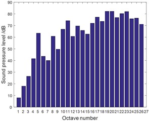
Fig. 5Identification of sound sources
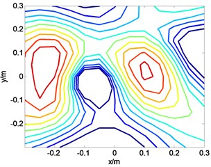
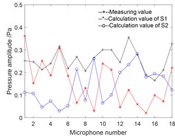
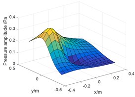
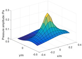
Fig. 6Pressure amplitude on holography surface: a) measuring values and separation values; b) reconstruction value of intake; c) reconstructed value of engine
a)
b)
c)
Fig. 6(a) shows the measuring values of pressure and calculation after separation of sources S1 and S2 on holographic surface with 18 points; Fig. 6(b) and (c) are reconstruction values of two sources on measuring surface after sound field separation. The amplitude in Fig. 6(b) is about 0.36 Pa, which is similar to the maximum pressure value of the source S1 after separation in Fig. 6(a); the amplitude in Fig. 6(c) is about 0.28 Pa, which is similar to the maximum pressure value of source S2 after separation in Fig. 6(a). From the above analysis, it shows that the coherent sound source of the motorcycle can be effectively separated.
5. Conclusions
Sound pressure data for motorcycles at 6000 r/min of engine speed, using 18-channel wheel array acquisition, the collected data is analyzed by 1/3 octave filtering, A weighting curve and beamforming source identification method. The results show that there are two significant coherent sources at the positions of front intake and engine noise in the motorcycle at 1600 Hz. In order to further confirm the noise amplitudes radiated by the intake air and the engine, the data is separated by the direct sound field separation method with single holographic surface and the pressure is reconstructed on the measuring surface. The sound pressure radiated by the intake noise and engine at 1600 Hz is found to be 0.36 Pa and 0.28 Pa, separately, so the main noise is the intake noise.
References
-
Zhou D. W., Li S. M., Wang X. X., et al. Noise source identification of near-field acoustic holography based on transfer function estimation. Chinese Journal of Scientific Instrument, Vol. 36, Issue 12, 2015, p. 2874-2880.
-
Zea E., Arteaga I. L. Single layer planar near-field acoustic holography for compact sources and a parallel reflector. Journal of Sound and Vibration, Vol. 380, 2016, p. 129-145.
-
Hald J. Scaling of plane-wave functions in statistically optimized near-field acoustic holography. Journal of the Acoustical Society of America, Vol. 136, Issue 5, 2014, p. 2687-2696.
-
Mao J., Xu Z. M., He Y. S., et al. The modified algorithm of sound field separation with double planes based on statistically optimal method. Journal of Mechanical Engineering, Vol. 51, Issue 15, 2015, p. 128-134.
-
Bi C. X., Zhang Y., Zhang X. Z., et al. Stability analysis of inverse time domain boundary element method for near-filed acoustic holography. Journal of Sound and Vibration, Vol. 143, Issue 3, 2018, p. 1308-1317.
-
Bai M. R., Lin J. H., Chen C. C. On optimal retreat distance for the equivalent source method-based nearfield acoustical holography. Journal of Sound and Vibration, Vol. 129, Issue 3, 2011, p. 1407-1416.
-
Bi C. X., Jing W. Q., Zhang Y. B., et al. Reconstruction of the sound field above a reflecting plane using the equivalent source method. Journal of Sound and Vibration, Vol. 386, 2017, p. 149-162.
-
Wang Z. H., Bi C. X., Zhang X. Z., et al. Sound field prediction and separation in a moving medium using the time-domain equivalent source method. Acta Acustica united with Acustica, Vol. 103, Issue 3, 2017, p. 401-410.
-
Bi C. X., Hu D. Y., Zhang Y. B., et al. Sound field separation method based on equivalent source method and double-layer particle velocity measurement. Acta Physica Sinica, Vol. 62, Issue 8, 2013, p. 275-283.
-
Mao J., Xu Z. M., He Y. S., et al. Separation technique of coherent sound sources using double planes of measurement. Journal of Vibration and Shock, Vol. 34, Issue 12, 2015, p. 146-149.
-
Bi C. X., Geng L., Zhang X. Z. Real-time separation of non-stationary sound fields with pressure and particle acceleration measurements. Journal of Sound and Vibration, Vol. 135, Issue 6, 2014, p. 3474-3482.
-
He Y. S., Wei X. B., Xu Z. M., et al. Sound field separation of coherent sources using double plane measurements based on equivalent source method. Chinese Journal of Scientific Instrument, Vol. 35, Issue 9, 2014, p. 2109-2115.
-
Braikia Y., Melon M., Langrenne C., et al. Evaluation of a separation method for source identification in small spaces. Journal of Sound and Vibration, Vol. 134, Issue 1, 2013, p. 323-331.
-
Song Y. L., Lu H. C., Jin J. M., et al. Near-field acoustic holography based reconstruction of sound field with coherent sound sources by single layer microphone array. Acta Acoustica, Vol. 40, Issue 1, 2015, p. 54-62.
-
Bai M. R., Chen Y.S., Lo Y. Y. A two-stage noise source identification technique based on a farfield random parametric array. Journal of Sound and Vibration, Vol. 141, Issue 5, 2017, p. 2978-2988.
About this article

This work was supported by the National Natural Science Foundation of China (Grant No. 61701397 and 51705419) and the China Postdoctoral Science Foundation (Grant No. 2019M653702).
