Abstract
The use of porous coatings is one of the passive flow control methods used to reduce turbulence and noise and vibrations generated due to fluid flow. A number of real-world applications rely on single or tandem cylinder systems like aircraft landing gears, chimneys, bridge pillars, etc. Using porous coatings for flow stabilization acts as a light-weight, cost-effective and customizable solution. The design and performance of a porous coating depend on multiple control parameters like lattice size, strut thickness, lattice structure, etc. This study aimed to investigate the suitability of MSLA 3D printers (Anycubic Photon and Prusa SL1) to manufacture porous coatings and to design and optimize porous lattices for flow control behind a cylinder. The Reynolds number used was 60000 and the flow measurements were taken using a hotwire probe. Different sets of experiments were conducted for single and tandem cylinder with varying control parameters to achieve the optimal lattice designs. The results show that the performance primarily depended on porosity, coating thickness, and coating shape. A high porosity thick coating gave a 70-75 % reduction in turbulence rate and also reduced the mean wake velocity. It was also seen that coating thickness is not linearly proportional to turbulence reduction and an optimal thickness exists for best performance.
Highlights
- Investigates manufacturability and control parameters of porous coatings
- Higher porosity coating gives lower turbulence rate and mean wake velocity
- Turbulence and mean velocity levels affected by lattice type due to difference in airflow resistivity
- Turbulence rate affected by surface irregularity and amount of open area on the outermost coating layer
- MSLA 3D printers suitable for self-supporting porous coatings
1. Introduction
Noise is primarily generated due to turbulence and unstable vortices. Acoustic power of sound is proportional to the 6th-8th power of velocity which leads to an intense increase in noise with a relatively small increase in flow velocity [1]. The vortices produced due to an airflow not only generate noise but can be catastrophic (especially in the aviation industry) and can cause major structural damage to the components in the wake. The strength of vortices depends on the flow momentum. Reducing mean velocity leads to a reduction in wake momentum, wake distance and helps in easy dissipation of the vortices. Therefore, reducing turbulence and mean wake velocity not only help in noise reduction but also help in reducing the damage to components in the wake region and prevent loss in mechanical integrity.
A porous coating over a cylinder deprives the wake region of momentum and leads to suppression of vortices. It also assists in a reduction in drag and pressure fluctuations which can help improve the overall efficiency of a system/component. A porous coating alters the flow field and widens the wake (Fig. 1). Energy dissipation takes place as the flow moves around and through the coating. This includes thermal loss due to skin friction between fluid particles and the surface, and viscous loss due to fluid viscosity and its flow within the coating [2].
The Reynolds number for this study i.e. 60000 falls in the subcritical range with a laminar boundary layer and turbulent vortex street. 3D characteristics of vortices can be neglected and the flow can be accurately represented in two dimensions [3].
Results from [1] suggest that the hardness of the porous material does not make a significant impact on noise reduction. Therefore, this study using 3D printed polymer resin porous coatings will be valid for applications where a metal powder bed fusion process will be used to create the porous material.
Fig. 1Instantaneous wake vorticity of a) a rigid and b) porous coated cylinder [1]
![Instantaneous wake vorticity of a) a rigid and b) porous coated cylinder [1]](https://static-01.extrica.com/articles/21438/21438-img1.jpg)
a)
![Instantaneous wake vorticity of a) a rigid and b) porous coated cylinder [1]](https://static-01.extrica.com/articles/21438/21438-img2.jpg)
b)
2. Methodology
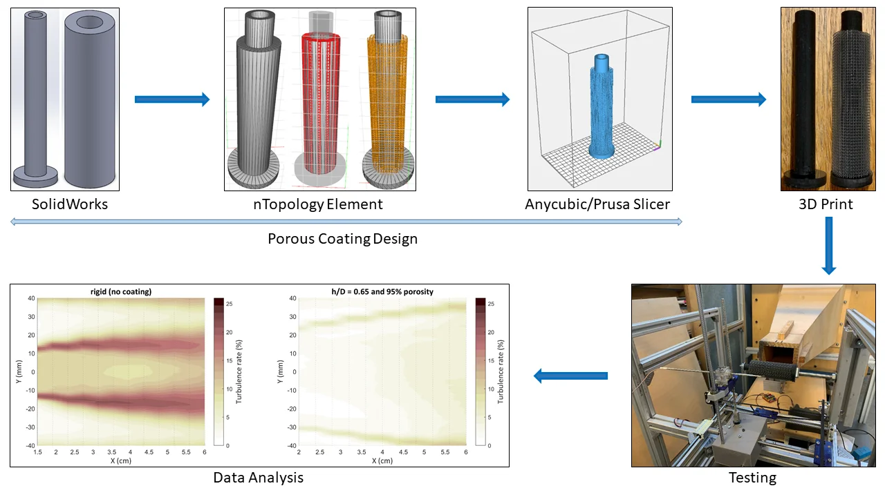
A variety of software and hardware were used in this study. Porous coatings were designed and controlled using SolidWorks and nTopology Element software. For probe movement and data acquisition, a combination of Matlab, Arduino with Adafruit Motor Shield, and Dantec StreamWare with StreamLine Pro and a P13 hotwire probe was used.
StreamLine Pro is a constant temperature anemometer system for turbulence investigations. It consists of a Wheatstone bridge and works on the principle of cooling effect provided by fluid flow over a heated body. As the air flows over the sensor, the tungsten wire in the sensor tends to heat up and lead to an unbalance in the Wheatstone bridge. Using an advanced feedback loop control, the bridge enables the temperature in the sensor to remain constant. The bridge voltage represents the heat transfer and is in direct relation with the airflow velocity. The Matlab code in conjunction with StreamWare allowed to take mean measurements for turbulence rate and mean wake velocity at each data point. This was done by having number of scans at each point = 200,000 and scans/second or rate = 40,000 i.e. an acquisition time of 5 seconds at each point.
The design of a porous coating can be controlled via several parameters. These are: lattice type (cubic, diamond cubic, etc.), lattice size/dimensions, lattice/strut thickness, coating thickness (/ ratio, where is the coating thickness and is the diameter of the core rigid cylinder), number of cells in the coating, and coating shape (e.g. helical, spaced discs, full, etc.). As porosity controls the airflow resistivity of the coating, it plays a critical role in regularizing flow around a cylinder, it was necessary to control the parameters which affect the porosity and to accurately calculate porosity for each designed coating.
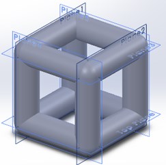
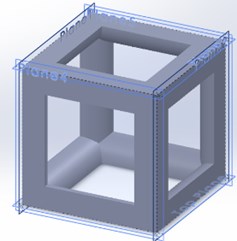
Since there was no existing method to calculate porosity for a coating, a new method using the existing tools had to be designed. For a selected lattice type/structure, its volume occupied i.e. packing fraction or porosity varies according to lattice size and lattice thickness. However, on changing the lattice thickness in nTopology Element, the dimensions of the thickened cell exceed the original cell dimensions. The solution to this problem was to convert the thickened cell into a CAD model, use reference planes in SolidWorks to create planes that outline the original cell dimensions and use these planes to trim the lattice to its original dimensions (Fig. 2). Using the volume occupied by the trimmed cell, porosity was calculated as:
For the cubic cell in Fig. 2 of lattice size 1.5 mm×1.5 mm×1.5 mm and thickness = 0.5 mm, the porosity was found to be: 78.96 %.
Fig. 2a) Untrimmed thickened cell and b) trimmed thickened cell
a)
b)
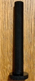
To successfully 3D print cylinders with porous coating, the slicing parameters were optimized according to the complexity of the porous lattice. resolution for printers used in this study was 47 μm [4, 5], and the layer height was varied between 22-29 μm. Sample 3D printed cylinders are shown in Fig. 3.
Fig. 3a) Rigid cylinder and b) cylinder with porous coating
a)
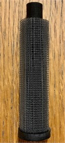
b)
Coating design parameters were varied in 10 experiment sets of single and tandem cylinder to find their optimal values for best performance.
3. Results
3.1. Set-1: lattice structure check
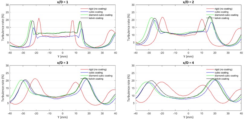
Cylinder-1 was a rigid cylinder with no porous coating. Cylinder 2,3 and 4 had a core rigid cylinder of 15 mm diameter and a porous coating of 3.75 mm. For each porous coating, the lattice size was 1.5 mm×1.5 mm×1.5 mm and the thickness was 0.5 mm. The only variable was the porosity of the lattice that occurred due to different structure types. The porosities of cubic, diamond cubic, and kelvin coatings were calculated as 78.96 %, 60.89 %, and 53.78 % respectively.
As per Fig. 4, Just behind the cylinder at 1, cubic coating provided nearly a 30 % reduction in turbulence as compared to the turbulence of a rigid cylinder. This reduction is not as compelling at 2 but is still better than a rigid cylinder. However, in the case of diamond cubic and kelvin cell coatings, there was no notable turbulence reduction at any position in the wake region. The reason for this was the porosity of different lattice structures. Since cubic lattice had higher porosity, it provided lower airflow resistivity i.e. lower hindrance and enabled airflow to lose momentum and energy when traveling through the channels of the porous medium. In the case of diamond cubic and kelvin cell coatings which had lower porosities, they acted as a rigid coating due to high airflow resistivity. This can be confirmed by their turbulence curves which were similar to the curve of a rigid cylinder. All cylinders with porous coating behaved similarly further away from the cylinder as the wake dispersed and the flow velocities reached closer to the free stream velocity. Based on these results, cubic lattice was chosen as the optimal lattice for further experiments.
Table 1Cylinders for experiment set-1
Set-1 | Lattice structure check |
Cylinder-1 | Rigid cylinder (15mm diameter) |
Cylinder-2 | Cubic coating |
Cylinder-3 | Diamond cubic coating |
Cylinder-4 | Kelvin cell coating |
Constant / coating thickness, lattice size, lattice thickness | |
Variable porosity | |
Fig. 4Turbulence graph for experiment set-1
3.2. Set-2: porosity check
Based on results obtained from set-1, all cylinders (except cylinder-1) used for set-2 had a porous coating of the cubic lattice. All cylinders (except cylinder-1) had a constant lattice size of 2 mm×2 mm×2 mm and a coating thickness of 4 mm. By keeping the lattice size constant, it was possible to vary the porosity by varying lattice thickness or strut diameter. Strut diameter used for cylinder-2, 3, 4 and 5 was 0.3 mm, 0.45 mm, 0.55 mm, and 0.65 mm respectively.
Fig. 5 clearly shows a reduction in turbulence with an increase in porosity. Just behind the cylinder at 1, the turbulence rate for cylinder-5 (80 % porosity) was at 15 %, whereas, for cylinder-2 (95 % porosity), it was at a considerably low value of 6 %-7 %. Similar observations can be made at 2 where the turbulence rate for cylinder-2 is about 55 % lower than that of cylinder-5. Although the wake at 2 is stronger than 1, high porosity still delivers a reduction in turbulence rate in comparison to low porosity coatings. Interestingly, at 3, the only cylinder which has noticeable reduction is cylinder-2 with 95 % porosity. Even with different porosities, the other 3 cylinders behave similarly at this position with comparable turbulence peaks. Once the wake disperses and the vortices lose their momentum i.e. at 4, all 4 cylinders have similar turbulence rates despite their difference in porosities. Based on these results, cubic lattice with 95 % porosity was chosen as the optimal lattice for further experiments.
Table 2Cylinders for experiment set-2
Set-2 | Porosity check |
Cylinder-1 | Rigid |
Cylinder-2 | 95 % porosity |
Cylinder-3 | 90 % porosity |
Cylinder-4 | 85 % porosity |
Cylinder-5 | 80 % porosity |
Constant lattice size, coating thickness | |
Variable porosity, lattice thickness | |
Fig. 5Turbulence graph for experiment set-2
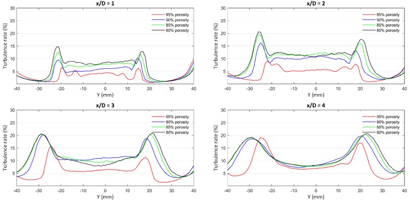
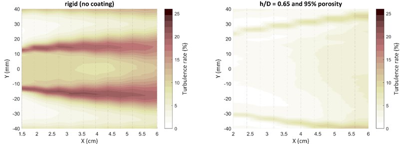
Fig. 6 compares the rigid cylinder with a porous-coated cylinder of 95 % porosity and a coating thickness of 9.75 mm. The contour shows the extent to which a porous coating can reduce turbulence in the wake of a cylinder. Near the cylinder, thick porous coating gave a 63-74 % reduction in turbulence. Unlike thin coatings that do not have a huge impact at far away in the wake, a thick coating gave about a 38 % reduction in peak turbulence rate. Due to a thick porous coating, air traveling through the channels of coating has more time and space to lose its kinetic energy. At the same time, the wake region widens and dissipates quickly due to lower momentum.
Fig. 6Turbulence contour for a rigid cylinder and a cylinder with thick porous coating
4. Conclusions
This paper investigated the suitability of MSLA 3D printers to manufacture porous coatings and to design and optimize porous lattices for flow control behind a cylinder. 3D printing proved to be successful for porous coatings as the printers had sufficient resolution to print thin and complex lattices. However, depending on the complexity of porous coating, the slicing parameters needed optimization to ensure a good quality print. The performance of these printers degraded when the structure was not self-supporting. Therefore, a thick coating of cubic lattice was more prone to failure than a kelvin cell lattice coating. A high ratio of lattice size to lattice thickness led to print failures as well. Thus, lower porosity coatings were easier to print as they generally had thicker lattices. The quality of prints also depended on the maintenance of the 3D printers. A clean and well-calibrated system resulted in lower print failures.
It was found that different lattice structures affect turbulence rate based on their porosity or packing fraction. A cubic lattice coating had the best performance as it had the simplest structure with no part of the structure inside the cell. It also had the most open area for air to enter the porous medium through the outermost layer of coating. However, for a lattice with a low porosity structure, it acted as a rigid cylinder due to high airflow resistivity and did not provide turbulence reduction.
In the case of porous coatings with varying porosity, it was found that porosity and turbulence reduction have a proportional relationship. Therefore, a high porosity coating gave a maximum reduction in turbulence and mean wake velocity. A thick porous coating gave up to 74 % turbulence reduction close to the cylinder. The distance in wake till which a porous coating had its effect depending on its thickness. Wake velocity for a thin coating at 4 reached free stream velocity whereas a thick coating still gave turbulence reduction at this position.
References
-
Takeshi Sueki, Takehisa Takaishi, Mitsuru Ikeda, Norio Arai Application of porous material to reduce aerodynamic sound from bluff bodies. Fluid Dynamics Research, Vol. 42, Issue 1, 2010, p. 015004.
-
Cao Leitao, Fu Qiuxia, Si Yang, Ding Bin, Yu Jianyong Porous materials for sound absorption. Composites Communications, Vol. 10, 2018, p. 25-35.
-
Lienhard John H. Synopsis of Lift, Drag, and Vortex Frequency Data for Rigid Circular Cylinders. Technical Extension Service, Washington State University, Pullman, 1966.
-
Anycubic Photon 3D Printer. Anycubic, https://www.anycubic.com/products/anycubic-photon-3d-printer.
-
Original Prusa SL1 kit. Prusa3D, https://shop.prusa3d.com/en/3d-printers/719-original-prusa-sl1-kit.html.
About this article

