Abstract
The intention of this study was to create a computational model in micro-scale that allows to imitate heat and mass transfer through three-dimensional textile layer with and without forced ventilation. The four ventilation rates were used 0, 0.2, 0.4 and 0.8 dm3min-1. Approximation of a unit cell geometry and heat transfer process were considered. The time-dependent and steady-state simulations are based on Navier-Stokes/Brinkman partial differential equations, and energy equation. A finite element modelling package Comsol Multiphysics was used for numerical simulations. The Laminar flow (.spf) and Heat transfer in fluids (.ht) modes were coupled with non-isothermal flow (.nitf) multi-physics. The post-processing analysis was done using Matlab software. The outcomes of simulation are temperature distributions, surface average temperature and relative humidity through the thickness of the representative volume. The results enable to create a macro-scale models for efficient simulation of heat exchange in textile packages.
1. Introduction
Thermal protective clothing (e.g. firefighters clothing, winter outdoor clothing, ballistic protection clothing) usually has a multilayer construction [1, 2]. Each layer has a specific function. For example, the outer layer protects against environment, the middle thermo-insulating layer protects the human body from excessive heat loss, the inner layer (usually 3D textile layer) enables the moisture and air exchange between the body and the surrounding environment [1]. The air gap between the skin and the inner layer is referred to as the ‘microclimate’. It can influence heat and mass transfer from or to the body (e.g. protective clothing, where microclimate is typically thicker and therefore the natural convection is more likely to occur) [3]. Investigation and development of a multi-layer textile package require understanding of the coupled heat and moisture transport phenomena in order to describe thermal comfort of clothing during wearing. Thermal insulation properties such as thermal resistance, water-vapor resistance and air permeability are crucially important comfort-related properties of fabrics [1]. However, theoretical investigations of the physical behavior of multi-layer textiles are complicated due to complex internal structure, coupled heat and moisture transfer and other physical processes, which occur in different space and time scales [2]. Computational Fluid Dynamics (CFD) tools are often used for simulation of heat and mass transfer processes in different engineering applications [4]. CFD tools and advanced mathematical models usually based on approximation of the textile due to complex multi-scale geometry, knowledge of parameters that describe the properties of the textiles. Measurements often do not provide all necessary data and relationships or require the access to complex and expensive experimental facilities [2-5].
In recent decades various aspects of heat and mass transport through the fabric have been investigated. Neves et al. [5] focused on methodologies and experimental procedures that allow to determine parameters such as fiber fraction, tortuosity as well as mass and heat transfer coefficients that are required as input parameters for numerical studies. In subsequent work [6] Neves et al. proposed a numerical model for the analysis of heat and mass transfer through multilayer clothing. It enables to study textiles and fibers characteristics during physical activities with different intensities (i.e. heat/sweat release). Mayor et al. [7] numerically studied the transport phenomena across horizontal clothing microclimates with natural convection by using the finite element method. In this study the effect of different microclimate thicknesses, external air temperature, external air velocity, and optical properties of the fabric inner surface was analyzed. The model coupled the classical set of continuity, momentum (Navier-Stokes) and energy equations in order to describe transport phenomena that occur in the simulation domain [7]. Siddiqui et al. [8] used the conjugate heat transfer model for investigation of heat transfer from hotplate to plain weft knitted fabric. Boussinesq approximation was used for the analysis of buoyancy-driven natural convection. The simulation was carried out using Abaqus software. The effective thermal conductivity and thermal resistance of the plain weft knitted polyester fabric were predicted [8]. Santos et al. [3] performed 2D transient simulations of air flow and heat transfer around a clothed human limb in the horizontal position. It was found that velocity, temperature and heat fluxes were dependent on the microclimate thickness. Angelova et al. [4] proposed a numerical model for simulation of the heat transfer through woven textiles by the jet system theory. A computational model was based on the Reynolds averaged Navier-Stokes partial differential equations (RANS), and the energy equation that was used together with - and RSM turbulence models. It was found that porosity of the woven macrostructure strongly affects the heat transfer. Simulations were carried out with Fluent CFD software package [4]. Puszkarz et al. [9] carried out computer simulation to study the performance of multilayer textile assembly exposed to heat radiation. The model was built using Solidworks Flow Simulation software that allowed to couple energy conservation equations and Navier-Stokes equations. The computational model outcomes were the transmitted heat flux density, the heat transmission factor, and the radiant heat transfer index that portrayed a good agreement with experimental data [9].
The aim of this study is to develop a computational model that predicts average temperature and relative humidity values through 3D textile using different ventilation rates, where ventilation flux is parallel to the layer and is directed through the air gaps of the 3D textile structure. The model was built using Comsol Multiphysics software.
2. Mathematical model of heat and mass exchange through 3D textile
2.1. Geometry of model
One of challenges using CFD tools is to obtain proper geometry approximation (homogenization of air and fibers) in order to save computational time simultaneously avoiding the meshing problems due to complex internal structure of the fabric. For this reason, in our previous work [10] a single-layer woven fabric was analyzed by numerically simulating air permeability and water vapor resistance tests. As a result, the model of 3D textile layer was constructed that consists of two simplified layers coupled with spacer yarn. The results portrayed a good agreement with experimental [11] and literature data [2].
The single-layer textile geometry was recreated in accordance with actual construction parameters measured by Zupin et al. [11]. Air permeability test was performed with the Air Permeability tester FX 3300 Labotester III (Textest Instruments) according to the ISO 9237:1995 (E) standard. The pressure difference was set 200 [Pa] on an area of 20 cm2 [11]. The local permeability of yarns was calculated by using the Gebart model. More details about local permeability calculation are presented in [12]. The water vapor resistance test was performed with The Sweating Guarded Hot Plate M259B according to the LST EN 31902:2002 / International standard ISO 11092:2014. Our numerical simulations were based on Navier-Stokes and Brinkman equations together with the continuity equation. Summary of experimental and computational values of air permeability and water vapor resistance are shown in Table 1. In this work the geometric model of a unit cell of 3D textile layer is used as created in our previous work [10].
Table 1Validation of measurement and computational model
No | A representative unit cell | Measured air permeability (mm/s) [11] | Numerical simulation air permeability (mm/s) [10] | Measured Water vapor resistance coeff. (s/m) [2] | Numerical simulation water vapor resistance (s/m) |
1 | One-layer measured density (21/15) [11] | 2391.67 | 2387.7 | - | 4.4675 |
2 | 3D textile | - | 1525.9 | 6.36 | 6.0769 |
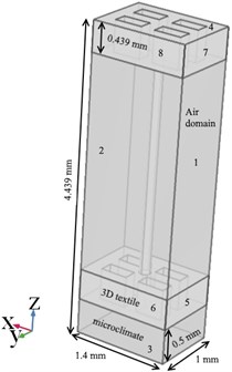
Geometry of three-dimensional textile layer is shown in Fig. 1. Model have air domain 1.4 mm×1 mm×4.439 mm in length ( direction), width ( direction), height ( direction), two textile layers with 0.439 mm thickness, and spacer yarn. Distance between layers is 3.061 mm, the spacer yarn radius is 0.08 mm.
Fig. 1Geometry of 3D textile layer with labels of boundary conditions and mesh diagram
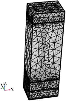
Different meshes (normal 502188, coarse 271751, coarser 127480, extra coarse 65740, and extremely coarse 43311) were adapted for simulation in order to find the grid-independent solution. It was found that a minimum number of finite elements was 65740. The extra coarse mesh that was used in simulations is shown in Fig. 1.
2.2. Heat and mass flow simulation
The computational model was created using Comsol Multiphysics 5.3a software. Comsol Multiphysics is finite element modelling package that has ability to couple different physics (partial differential equations (PDE)) or multi-physics within a single model domain. PDE can be specified using physics-based user interfaces or entered symbolically. The COMSOL simulation environment consists of defining geometry, specifying physics, meshing, solving, and then postprocessing [13]. The simulation domain consists of union of two subdomains (air domain), (three-dimensional textile layer). The governing equations are based on energy conservation (heat transfer) equations and Navier-Stokes/Brinkman equations. The assumptions were made stating that the air flow is incompressible Newtonian single phase flow. Also, steady-state and time-dependent simulation were conducted considering the laminar flow model.
The fluid flow equations were performed by the classical set of continuity (Eq. (1)), momentum equation that was considered Navier-Stokes equations (Eq. (2)) in case of free flow, and Brinkman equations (Eq. (3)) in case of porous media domain. The steady-state governing equations of the fluid flow read as:
where – the gradient operator, – velocity vector of fluid flow in [m/s], - density of fluid in [kg/m3], – pressure in [Pa], – dynamic viscosity of fluid [Pa·s], – identity tensor and denotes external force (i.e. buoyancy force acting on the fluid elements [N m−3]) vector. At micro level Brinkman equation requires local permeability [m2] value and porosity as input of intra-yarn. The values were taken from literature [12] as 1.64·10-11 [m2] and 0.58 respectively.
Thermal energy equation (Eq. (4)) in the fluid region was expressed as:
where – specific heat capacity in [J/kg K], – overall heat transfer in [W], – effective thermal conductivity of the fluid-solid mixture in [W/m·K].
The fluid domain presents the moist air at ambient relative humidity 40 % (0.4). The relationship between the water-vapor partial pressure and the saturation water-vapor partial pressure reads as:
A summary of the boundary conditions applied in this study is presented in Table 2. The labels of boundary conditions are shown in Fig. 1.
The boundary 3 represents skin with a constant temperature of 37 ℃. Three different mass flow rates (0.2, 0.4, 0.8 dm3min-1) of ventilation layer (boundary 1) were considered. The covective heat transfer coefficient 8.4746 W/(m2·K) of three-dimensional textile layer is based on measurements according LST EN 31902:2002 standard [2].
Table 2Boundary conditions of simulation
Boundary | Fluid flow | Boundary | Heat transfer |
1 | Inlet (mass flow): 0.2, 0.4, 0.8 dm3min-1 | 4 | Convective heat flux:, 8.4746 W/(m2·K) |
2 | Outlet: 0 Pa | 3 | Temperature: 37 ℃ |
Textile walls | No slip: | default | Thermal insulation: |
default | Slip: | Note. velocity vector, n normal vector, heat flux vector, external temperature. | |
3. Numerical results
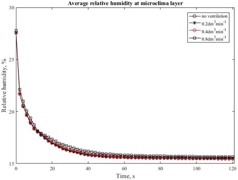
The intention of this work was to portray the process of forced heat convection through the three-dimensional textile layer by the different ventilation rate. Fig. 2 and Fig. 3 summarize the temperature distribution and average temperature value at different through-thickness positions along axis with ventilation rate of 0.8 dm3min-1 and without ventilation rate. The increasing intensity of ventilation rate reduces the temperature in the microclimate. The microclimate is represented in the middle of air gap between the skin and bottom of textile layer at the –3.90 mm. In case of ventilation rate of 0.8 dm3min-1 temperature is 36.19 ℃ and without ventilation rate is 36.34 ℃. Fig. 4 and Fig. 5 presents examples of time relationships of average temperatures in the middle of microclimate gap layer (–3.90 mm) and outer surface of the 3D textile (0.289 mm). There is not significant difference between 0, 0.2, 0.4 dm3min-1 ventilation rate in the microclimate. However, the tendency and effect of increasing ventilation rate is shown at ventilation rate 0.8 dm3min-1. The Fig 6. demonstrates that relative humidity increases with ventilation rate.
Fig. 2Simulation results of 3D textile layer. Distribution of the temperature without ventilation rate
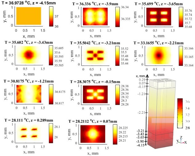
Fig. 3Simulation results of 3D textile layer. Distribution of the temperature with ventilation rate of 0.8 dm3min-1
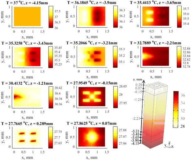
Fig. 4Time relationships of average temperatures in the middle of microclimate gap at four different values of the ventilation rate 0, 0.2, 0.4 and 0.8 dm3min-1
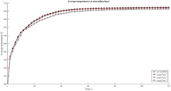
Fig. 5Time relationships of average temperatures in the outlet at four different values of the ventilation rate 0, 0.2, 0.4 and 0.8 dm3min-1
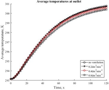
Fig. 6Time relationships of average relative humidity in the middle of microclimate gap (z position –3.9 mm) at four different values of the ventilation rate 0, 0.2, 0.4 and 0.8 dm3min-1
4. Conclusions
A computer simulation was conducted on the heat and mass transfer in micro scale using Comsol Multiphysics software. The numerical simulations were performed as stationary and time dependent. The first study is dealing with distributions of the air temperature that can be depicted in whole computational domain. The time dependent study concerns relative humidity effect, the thermal performance of three-dimensional textile exposed by ventilation rate. This study shown that relative humidity is dependent from ventilation rate. The input parameters of simulation were based on experimental and literature data. The findings such as relative humidity, surface average temperature that is required parameter for determination of thermal resistance can be applied in macro-scale models for efficient simulation of heat and mass exchange through textile packages.
References
-
Matusiak M., Kowalczyk S. Thermal-insulation properties of multilayer textile packages. Autex Research Journal, Vol. 14, Issue 4, 2014, p. 299-307.
-
Barauskas R., Abraitiene A. A model for numerical simulation of heat and water vapor exchange in multilayer textile packages with three-dimensional spacer fabric ventilation layer. Textile Research Journal, Vol. 81, Issue 12, 2011, p. 1195-1215.
-
Santos M. S., Oliveira D., Campos J. B. L. M., Mayor T. S. Numerical analysis of the flow and heat transfer in cylindrical clothing microclimates – Influence of the microclimate thickness ratio. International Journal of Heat and Mass Transfer, Vol. 117, 2018, p. 71-79.
-
Angelova R. A., Kyosov M., Stankov P. Numerical investigation of the heat transfer through woven textiles by the jet system theory. Journal of the Textile Institute Vol. 110, Issue 3, 2019, p. 386-395.
-
Neves S. F., Campos J. B. L. M., Mayor T. S. On the determination of parameters required for numerical studies of heat and mass transfer through textiles – Methodologies and experimental procedures. International Journal of Heat and Mass Transfer, Vol. 81, 2015, p. 272-282.
-
Neves S. F., Campos J. B. L. M., Mayor T. S. Effects of clothing and fibres properties on the heat and mass transport, for different body heat/sweat releases. Applied Thermal Engineering, Vol. 117, 2017, p. 109-121.
-
Mayor T. S., Couto S., Psikuta A., Rossi R. M. Advanced modelling of the transport phenomena across horizontal clothing microclimates with natural convection. International Journal of Biometeorology, Vol. 59, Issue 12, 2015, p. 1875-1889.
-
Siddiqui M. O. R., Sun D. Conjugate heat transfer analysis of knitted fabric. Journal of Thermal Analysis and Calorimetry, Vol. 129, Issue 1, 2017, p. 209-219.
-
Puszkarz A. K., Machnowski W., Błasińska A. Modeling of thermal performance of multilayer protective clothing exposed to radiant heat. Heat and Mass Transfer, Vol. 56, 2020, p. 1767-1775.
-
Gadeikytė A., Barauskas R. Numerical Simulation of Air Permeability Coefficient of 3D Textile Layer, 2019, https://www.comsol.com/paper/numerical-simulation-of-air-permeability-coefficient-of-3d-textile-layer-82471.
-
Zupin Ž., Hladnik A., Dimitrovski K. Prediction of one-layer woven fabrics air permeability using porosity parameters. Textile Research Journal, Vol. 82, Issue 2, 2012, p. 117-128.
-
Pezzin A. Thermo-Physiological Comfort Modelling of Fabrics and Garments. Ph.D. thesis., 2015.
-
Li Q., Ito K., Wu Z., Lowry C. S., Loheide S. P. COMSOL multiphysics: A novel approach to ground water modeling. Groundwater, Vol. 47, Issue 4, 2009, p. 480-487.
Cited by
About this article

