Abstract
Because 3D Slicer has many applications in medical imaging and has high scalability, it has been studied by many people engaged in medical and development work. In order to facilitate the clinical use of 3D Slicer software in craniocerebral surgery, this article re-developed the graphical user interface (GUI) in the software. The development process can be divided into four steps: app, Qt and Visual Studio, software packaging and external modules. Through the application of Qt and Visual Studio, GUI can be built and modified to simplify the operation steps and operation interface, in order to meet the clinical use needs of doctors. At the same time, this paper demonstrates the operation results in the workflow, such as medical image fusion and neural bundle modeling.
Highlights
- We show how to use VS and QT to re-factor the source code of 3D slicer. In other words, it is how to carry out the secondary development of 3D slicer.
- We have carried on the process processing for the operation of Hematoma.
- We used slicer software developed by us for Image Fusion (through Rigid Registration), Hematoma Modeling, and establishment of Intracranial Nerve Bundle.
1. Introduction
In this era of advanced technology, doctors hope to heal patients faster. The development of medical image processing technology enables doctors to diagnose and treat diseases faster and more accurately. 3D Slicer is a powerful, open source and free medical image processing software [1], suitable for the visualization of human organ images. However, there are problems with many operations and complicated interfaces, which cannot meet the rapidity requirements in clinical operations. In order to improve the utilization of 3D Slicer software in cranial surgery, this article re-developed the GUI of 3D Slicer and established the workflow of cranial surgery to optimize the operation steps and simplify the user interface.
2. Preparation
2.1. 3D slicer introduction
3D Slicer is a software platform for researching medical image analysis and visualization. It is developed on the basis of open source software such as VTK, ITK, Team and Qt. It has perfect image processing technology and supports many image analysis algorithms such as diffusion tensor imaging and magnetic resonance imaging. At the same time, it has many modules, extensions, powerful plug-in functions, and can add algorithms and applications. It is suitable for multi-mode imaging, supports standard medical image format, and has bidirectional interface of the device. Because of the powerful function of 3D Slicer software and the strong function of medical image processing, it is chosen as the object of secondary development.
2.2. Selection of software compiling environment
As we all know, there are currently three main software development environments: Windows, Linux and Apple's Mac Os system. Among them, Apple's operating system is a graphics operating system based on the Unix kernel, which usually cannot be installed on ordinary computers. Considering the popularity, our development environment should be chosen between Windows and Linux. Next, we will compare the Windows and Linux systems and choose the most suitable one.
(1) Operation mode: Windows has abandoned the Dos character operation mode, mainly researching the graphical interface. It makes Windows easy to operate. If you are the first time to contact with development, it is very convenient and easy to use. Linux chose to focus on character mode, using graphical interface as an accessory to the system. Linux gives us a different way of operating from Windows, which is more suitable for software developers to use.
(2) Software and support and operation system security [2]: the Windows system has the advantages of software quantity and quality, as well as important support and services provided by the government. For security, Windows updates the system by patching, but because of its popularity, many virus authors choose to use Windows to spread the virus. The software of Linux system is mostly open source software. Users can make customized modification and redistribution. Because of open source and lack of financial support, some software lacks quality and experience. But behind it is the support of all Linux developers and the open source software community around the world. For security, Linux system has a large number of network management, services and other functions, providing a large number of network management software, network analysis software and network security software.
(3) Development environment: The Windows system has the support of Microsoft, and the maintenance difficulty is much lower than other systems. At the same time, the development efficiency is high, the novice is friendly, compatibility is strong, do not need to consider different distributions. Linux system has an open source environment, excellent development tools, extensive hardware support, good security and reliability.
In summary, Windows system is more suitable as a secondary development environment.
3. Secondary development of 3D slicer
3.1. Download and compilation of source codes
3.1.1. Download of source codes
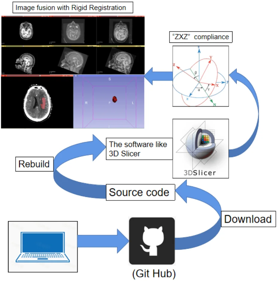
Because 3D Slicer belongs to open source software, its source codes is hosted on Git Hub. There are two kinds of software, SVN and Git [3], to download the source codes. Among them, SVN is an open source version control system, through the use of branch management system for efficient management; Git is an open source distributed version control system, which can effectively and quickly handle projects. This development chooses Git for codes download and hosting. By downloading Git software and using Git Bush for command line processing.
3.1.2. Compilation of source codes
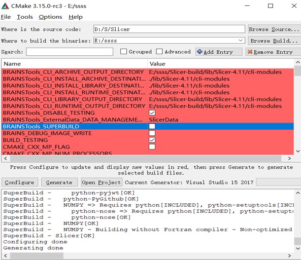
After downloading the source code to the specified folder, we start to compile the source code [4]. C++ general compiler software is CMake, the use of CMake software for compilation. Because the open source software is through the C++ for the bottom codes, joined the VTK, CTK and other libraries, developed the interface with Python and wrote the module, we should use the same C++ language written Qt graphics processing software interface.
Before compiling, we need to download Qt and install it into the specified folder.
Fig. 1CMake compilation
Enter Qt_DIR in Add Entry and select the Qt folder in the CMake directory under the Qt path.
Fig. 2Configure the QT environment for source codes
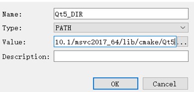
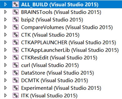
Fig. 3Use visual studio to generate SLN files
Click Configure to compile and select MVSC_2017×64. At this point, because CMake is not installed in the same path as Git, the first error will occur. We need to find the PATCH file under Git manually.
Once we find the path, click Configure again to keep it running until the word Configure Done appears. Then click Generate and Open Project in turn, and A. SLN file will be generated and opened with VS2017. Right-click ALL_BUILD and select the generation option. Because it’s the first time to generate, you need to download a lot of files, so the generation time will be very long.
Once generated, a corresponding Slicer.SLN file is generated under the Slicer-build folder. Use CMD of Windows system to open operation. (This process is to configure the environment for the SLN file, which cannot be debugged if opened directly).
3.2. Operating with Qt
3.2.1. Introduction of Qt
Qt [5] is a cross-platform C++ graphical user interface application development framework, mainly used to develop graphical user interface (GUI [6]) programs, but also can develop no interface command line (CLI) programs. In addition to drawing the interface, Qt includes many other functions, such as multi-threading, database access, image processing, audio processing, network communication, file manipulation, and so on.
3.2.2. How to use Qt in visual studio
When we see the 3D Slicer source codes, we will find there are Qt iconic UI files in it. Although Qt is installed, it’s still unable to open UI files in VS. For solving that, we need to search for Qt plug-ins and install them in Tool → Extension and Update. Restart Visual Studio after tool was installed.
3.2.3. Two ways of using Qt
(1) Qt Creator: The tool is writing codes to create the interface. If you read the source codes, you can find that the software has a part, used to write the interface. Especially, for the creation of buttons, slot function writing and so on, this work has a great role.
(2) Qt Designer: The pattern is an interactive visual GUI design tool, which can help developers develop interfaces quickly. It use a way which dragging the corresponding graphics to create the corresponding buttons and layouts, insert fonts and so on.
Fig. 4Use of QT in visual studio
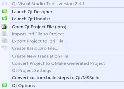
The method used in the secondary development is the combination of the both. Firstly, Qt Designer is used to create the button. At which time, the button is not connected. Then Qt Creator is used to add and connect slot functions in source codes. Finally, the connection operation between button and slot function is carried out in Qt Designer. Because this way is easier. The combination of both simplifies the complex codes written by Creator and facilitates the layout adjustment of GUI [7].
3.2.4. Establishment of 3D slicer workflow
We use Qt to integrate the functions of brain modeling and hematoma modeling, and establish the workflow of craniocerebral surgery in the end.
Fig. 5Establishment of workflow
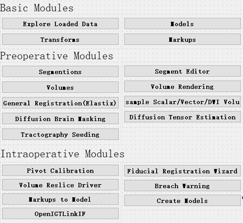
In the original interface of slicer, only the basic data module and volumes module are useful, so for the medical procedures of intracranial hematoma, the required modules are integrated into the initial interface.
When operating in the original interface, we need to remember the spelling of the name of each module, and we also need to search the module constantly, which consumes time. At the same time, the English interface also has a certain impact on the operation of doctors, so we can carry out the important module of Chinese.
In the original slicer, it takes about 40 minutes to complete the hematoma modeling, image fusion, nerve bundle modeling and intraoperative operation, which is more skilled for slicer users. After the interface is integrated, the modules that need to be used are obvious and arranged in the order of work flow. The preoperative and intraoperative operations can be completed in turn according to the order from left to right and from top to bottom. The completion time is about 30 minutes. For the first time users of slicer, the integrated interface will be more fluent.
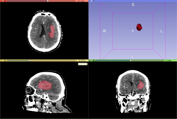
Hematoma modeling in the process is demonstrated in Fig. 6.
3.3. Some algorithms and demonstration involved in the process
3.3.1. Partial image processing display
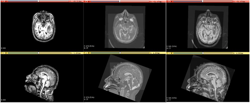
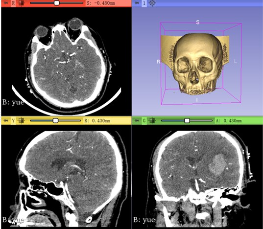
Using the medical image registration kit provided by SlicerElastix [8, 9], rigid body transformation only needs space translation and rotation. In nuclear magnetic resonance images, space can be translated or rotated along , , axes. Therefore, rigid body transformation only needs 6 degrees of freedom. In addition, the toolkit also includes affine transformation and nonlinear transformation. Among them, in addition to the translation and rotation of rigid body transformation, there are six additional degrees of freedom for image zooming in, zooming out and tilting. Finally, the most complex nonlinear transformation has one more local deformation of the image than affine transformation, so it needs more than 12 degrees of freedom.
Fig. 6Hematoma modeling demonstration
Considering the time of image registration, and the medical data used in the research do not have too large image skew and deformation, the fast registration speed of rigid body transformation is selected.
Fig. 7From left to right, Mr, DTI and CT, DTI and Mr registration effect
3.3.2. Rigid registration algorithm
Rigid transformation requires the original image to be transformed into another coordinate system through a mapping, and at the same time, the original image in this coordinate system is consistent with the image to be registered. The general formula is: , where is the coordinates of the points under the image to be registered, is the coordinates of the points under the original image, is the rotation matrix, and is the translation matrix. The rotation matrix is described by Euler angle.
Under the description of Euler angle, the matrix rotating about the -axis is:
The matrix rotating about the -axis is:
The matrix rotating about the -axis is:
The rotation matrix of Euler angle decomposes the rotation of rigid body into three parts (blue is the starting coordinate system and red is the destination coordinate system).
Fig. 8Demonstration of Euler angle rotation
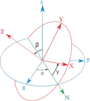
Step 1: Rotate the -axis so that the -axis coincides with the -axis (the Intersection line of the X-O-Y planes of the two coordinate systems before and after the rotation).
Step 2: Rotate around the transformed -axis (-axis) so that the -axis coincides with the rotated -axis.
Step 3: Rotate around the -axis after transformation to make the two coordinate systems completely coincide.
According to the order of the axis of rotation, this set of Euler angles is called “ compliance”. So the rotation matrix of Euler angle is .
3.4. The software package
3.4.1. Package with visual studio (VS) [10]
(1) Install VS2017 package plug-in Microsoft Visual Studio 2017 Installer Projects, also in the tool to Extension and Update to online search and download. Restart after installation.
(2) Select the solution, add to build new Project, in other Project type select Setup Project to create. In the pop-up dialog box, we should find the project output and select the main project output item. Then select the main output and create the shortcut.
(3) In solution explorer, we can select the new project and right click to generate. After that, the software is packaging.
3.4.2. Universal software packaging
For the secondary development of software, packaging is the last step. We can choose to generate and package directly from the package project given by the source code. In this paper, we first give a general method of using vs2015 to package [11].
(1) Select the solution, right-click add and choose new project, and select other project types to “visual studio installer” to setup project. Generate the package project under the solution of this project.
In the above figure, “application folder” indicates the files to be added to the application to be installed; “user’s programs menu” indicates the contents displayed in the start menu after the application installation is completed; “user’s desktop” refers to the contents displayed on the desktop (generally, the. Exe shortcut of the application).
(2) Right click “Application Folder” to Add File and select the “.exe” file in the debug directory that has been compiled.
After that, the VS dependency will be added automatically. You can see if there are missing dependencies in the list on the right.
If the dependent file contains a folder, you need to add it manually.
(3) Add. Exe shortcut. Put it in the “user’s desktop” and “user’s programs menu” folders. Select shortcut, you can add Icon, name, description and other operations in the “properties” column.
(4) Add an uninstall program. Copy operation (2), and according to the path “C: Windows / system32\ Msiexec.exe” add to “Application Folder”. Create a shortcut and rename it uninstall and put it in the “user’s programs menu”. Next, you need to indicate the project to be unloaded for exe. Select the item, select product code in the property, copy it into arguments, and add “ / x + space” at the beginning.
(5) If we want to optimize the interface or add some restrictions, you can select add in the view list. Only the default installation path is added here. Select “application folder”, right-click to modify the installation default folder, and then directly modify it to the specified path.
(6) Finally, rebuild the installation project. The generated installation files can be found in the debug or release directory of the installation project.
However, since 3D slicer adds packaged source code to the source code, you only need to right-click generate package to get the files of type exe in the specified folder.
3.4.3. Possible problems and solutions
In The first time, we package failed, that means we lack of NSIS software. After packaging again, we package successful.
(2) After Software packaged, it still had the console. In order to solve the above problems, we have the following operations. First of all, in the CMake, leave the compile type only for Release. If it is no avail, We can add the following codes “#pragma comment (linker, “/subsystem: windows/entry: mainCRTStartup”)” at the beginning of the program. If you want to do it once and for all, you can follow those steps. Step One: Open “Configuration properties” to “Linker” to “System” to “Sub-System” and set to “Windows (/SUBSYSTEM:WINDOWS)”. Step Two: Open “Advanced” to “Entry Point” and set to “mainCRTStartup”. After that, as long as we don't input ourselves, there won’t be a console.
4. External module
4.1. Introduction of external modules
3D Slicer has an open source platform, and many researchers release their open source modules on the extension platform. Most modules are open source and can be used for re-development.
(1) 3D Slicer module preparation. Slicer has a lots of interfaces for different programming languages. Modules can be written in many programming languages, but Python is recommended. Create a new extension to store our own module, select and create our own Script modules. Once the creation is successful, we can use Python to open and write.
(2) Slicer module installation. In the EXTENSION module, open the module store and select the module we want to download.
4.2. External module compilation and import
4.2.1. Download of external module source codes
Use Git Hub to find and download the codes, or in the extension module, open the module to be downloaded and find the corresponding source download link.
4.2.2. Compilation of external modules
We can use CMAKE to compile the downloaded codes. Before compiling, you need to let Slicer_DIR in Add List and select the slicer-build folder under the build folder path. Because 3D Slicer is a basic to write and develop the codes of all modules, 3D Slicer needs to be added as the compilation environment of external modules. Sometimes, because 3D Slicer is developed on the basis of VTK, CTK and other libraries, it is also necessary to add VTK-build and CTK-build paths to configure the environment of external modules [12].
4.2.3. Import of external module
After CMAKE compiles, we should Open the Project and right-click on ALL_BUILD next. The external module is based on Slicer, so the source codes also comes with a PACKAGE project, right click INSTALL project or PACKAGE module. After a successful build, a new folder is generated in its root directory. It’s similar to software packaging.
In the open Slicer, we should select this one that is the “Setting” to Modules, and select the import module, import the corresponding files under the newly generated folder in turn, and finally restart Slicer. After that, we import successfully.
4.2.4. Module development
3D slicer supports three types of modules: command line interface (CLI), Loadable module and Script module, but their final interface presentation is no different [12].
CLI is a stand-alone executable file, which is usually implemented in C++. However, the CLI can only do limited input and output, using simple parameter types, without user interaction. In the latest slicer version, slicer can run almost all Python scripts as cli modules by providing interface description .xml files.
Loadable module is a C++ plug-in built by 3D slicer, which can completely control slicer for its operation. The CLI optimizes the complex computation, can use C++ shared library, can realize the complete independent UI.
Script module is written in Python computer language, API can fully access VTK, QT, MRML and so on. It is recommended to use script module for rapid prototyping design and custom workflow development.
4.3. Display of some expandable modules
1) SwissSkullStripper Module [13]: The module is to model the skull and peel off the scalp, and keep the complete skull, which is convenient for the selection of the patient’s skull position during operation.
Fig. 9Skull rendering
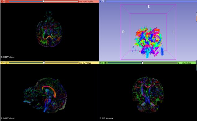
2) SlicerDMRI Module [14, 15]: This module reconstructs the DTI image after image registration, so that doctors can have a general grasp of the important nerve distribution of the patient's brain.
Fig. 10Neural bundle modeling in brain
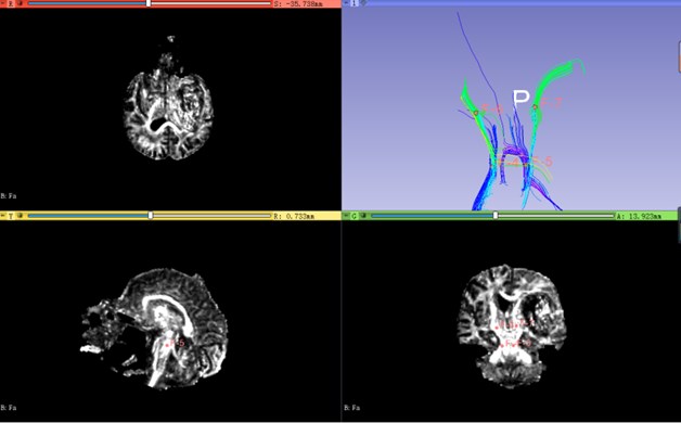
3) UKFTractography module: The module can generate the nerve bundle through each point in the point set through a point set, and can generate the nerve bundle in real time, with high practicability.
Fig. 11Modeling of corticospinal tract
5. Conclusions
3DSlicer is a particularly friendly medical image processing software. We can conduct various medical experiments through 3DSlicer, which provides great convenience for medical workers and researchers. The establishment of workflow not only facilitates the operation of medical workers, but also provides specific steps for scientific researchers to complete a series of operations such as image processing more quickly. In the future, 3DSlicer’s powerful image processing function will make clinical operations more accurate and concise.
References
-
Wenbiao Zeng, Luping Fang, Yujie Wan Internationalization method of 3D Slicer for medical image processing platform. Journal of Computer Systems, Vol. 22, Issue 7, 2013, p. 7-11.
-
Li Xiaoyan Analysis of the difference between Linux and windows. Science Association Forum (second half), Vol. 8, 2010, p. 56-57.
-
3D Slicer Build Instructions, https://www.slicer.org/wiki/Documentation/4.1/Developers /Build_Instructions.
-
3D Slicer. Compile Slicer Code, https://www.slicer.org/wiki/Documentation/4.10/Developers /Build_Instructions/Compile.
-
Yuan Yuan Yuan, Wang Yanhong, Jiang Ling, Jiang Yang Application of C ~ (+ +) class library QT in the development of numerical simulation software. Modern Electronic Technology, Vol. 33, Issue 2, 2010, p. 80-83.
-
Blanchette J., Summerfield M. C++ GUI QT4 Programming. Electronics Industrial Press, BeiJing, 2010.
-
3D Slicer Style Guide, https://www.slicer.org/wiki/Documentation/Nightly/Developers/Style_Guide.
-
Klein S., Staring M., Murphy K., Viergever M. A., Pluim J. P. W. Elastix: a toolbox for intensity based medical image registration. IEEE Transactions on Medical Imaging, Vol. 29, Issue 1, 2010, p. 196-205.
-
Shamonin D. P., Bron E. E., Lelieveldt B. P. F., Smits M., Klein S., Staring M. Fast parallel image registration on CPU and GPU for diagnostic classification of Alzheimer’s disease. Frontiers in Neuroinformatics, Vol. 7, 2014, p. 50.
-
Firefly_cjd.Package with visual studio installer of vs 2015, https://blog.csdn.net/Firefly_cjd /article/details/77450839.
-
zsq_fengchen. Advantages and disadvantages of Linux, differences between Linux and windows, https://www.cnblogs.com/zhaosq/p/10839147.html.
-
3D Slicer. Documentation/Nightly/Developers/Modules., https://www.slicer.org/wiki/Documentation /Nightly/Developers/Modules.
-
Bauer S., Fejes T., Reyes M. A skull-stripping filter for ITK. Kitware, 2017, http://doi.org/10.5281/zenodo.811812.
-
Fan Zhang, Noh Thomas, et al. SlicerDMRI: diffusion MRI and tractography research software for brain cancer surgery planning and visualization. JCO Clinical Cancer Informatics, Vol. 4, 2020, p. 299-309.
-
Norton Isaiah, Essayed Walid Ibn, et al. SlicerDMRI: open source diffusion MRI software for brain cancer research. Cancer Research, Vol. 77, Issue 21, 2017, p. 101-103.
About this article

This work was supported by the National Science Foundation of China (51674121,61702184), Tangshan Innovation Team Project (18130209B,18130210B), the Hebei Key Laboratory of Science and Application, Research and Practice Project of Higher Education Teaching Reform in Hebei Province (2017GJJG111) and Ministry of Education Production University Cooperation Education Project (201802305012).
