Abstract
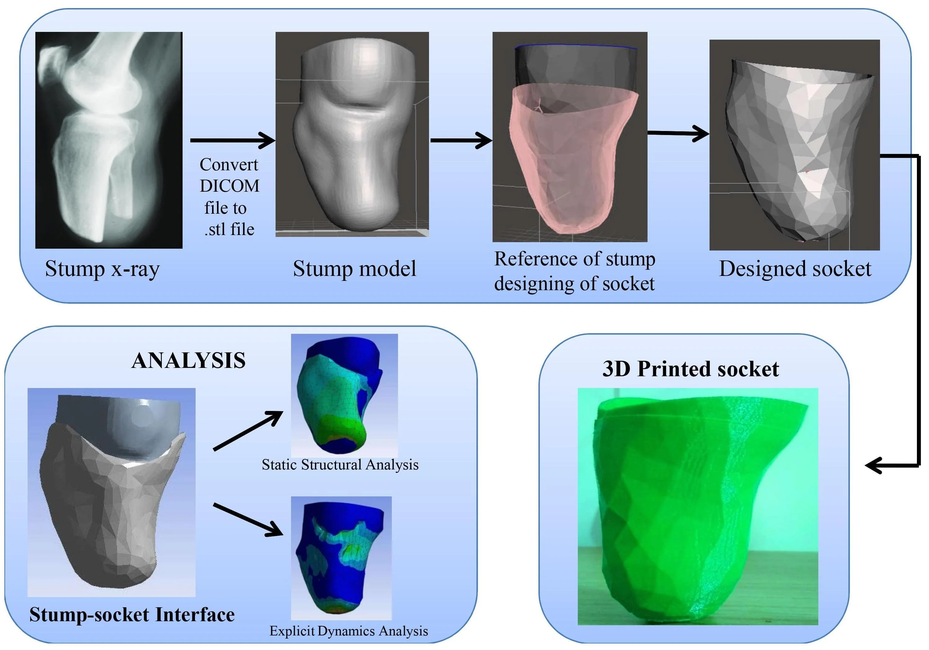
The work aims to design and development of a prosthetic socket for lower limb amputation with 3D printing technology for a patient. It is focused on the finite element-based simulation and analysis by utilizing CT based three-dimensional (3D) model. In this study, image processing software is used for extracting models from CT images and obtained models are modified in CAD modeling software in STL format. These files are examined in ANSYS simulation to performing the static and dynamic analysis of the prosthetic stump and socket. Based on the simulation results, the model is to prepare with the 3D printer. The results from the 3D model simulation can be used to estimate the pressure distribution. The function of the below-knee prosthesis is to control the leg under static and dynamic conditions. The prosthetic sockets evolution and prefabrication by using finite element approach very interesting topic in this research work for the fabricators. Finally, it helps contribute to an overall prefabrication evaluation system to allow healthcare providers. The patients are comfortable with the transtibial prosthetics made of 3D printers with the simulation process to fit.
1. Introduction
There is a major and rising socioeconomic problem in the treatment and recovery of individuals after lower limb amputation. The Prosthetics and Orthotics of International Society states that there is a validate requirement for availability of modern technology in prosthetic limb components and there is need to develop evidence based practice in the clinical community [1]. There is significant occurrence of skin disorders [2] due to this need to transfer the elevated forces of compressive and shear across the prosthesis and limb of residual. To bear regular loads of compressive and shear the tissues of residuum are not used as the tissues of plantar in the foot are [3, 4]. Predicting the tissue damage of maximum internal strain at present preferred to surface stresses [5] so suitable models of elasticity, pre-strain from socket donation are necessary.
Relevant research made by the following works referenced included the generation of all geometry sample loads and boundary conditions including all pre-stresses from wearing of the socket [6] and the quasi-dynamic loading [7-9] the use of soft tissue predicted models demonstrating and capability nonlinear hyper elasticity [9, 10] and the subject variability is assessed by simulating various cases [9, 11]. The comparison between BKA socket studies other papers that modeled the socket [6, 12] indicates that this expectation induced an increase in interface stresses then various factors that effects of prosthetic user socket liners complicate the result.
Rehabilitation after amputation is generally aimed at restoring functional independence by encouraging the use of a prosthetic limb for ambulation. It also involves an iterative and labor-intensive method to suit a traditional prosthetic limb using a suspension socket [13, 14]. Due to feverishness, movement and moisture or over many months these factors can differ over the course when post-operative swelling subsides, muscles deterioration and fleshy tissues remodeling to allow the transfer of socket-skeleton load [15-17]. This condition will impact on the quality of life of a person by inconvenience and physical restrictions causing minor problems in human body’s movement system such as lower back pain, osteoporosis and osteoarthritis [18]. Inappropriate joint fit may causes to dermatological issues where as contact keratosis and dermatitis [2, 19] and the interior tissue strain and ischemia may follow to severe material damage in extreme cases [20]. Due to suffocation and longer exposure to the harmful material of the prosthesis [21] irritation and risk of skin infections are increased in a humid environment.
For instance the mechanism by which victims put in a liner to their limbs of residual before applying a socket can add trapped air that can cause skin rubbing, heat and potentially contribute to burning sensation [22]. Significant developments have been made in knowing the level of strain severity and extent of tissues [5]. The adaptive mechanisms are extremely complex and do not know much. Finite element analysis (FEA) is method for computational modeling that can provide comprehension of magnitudes and load distributions of soft tissue which can produce a base of evidence to design an assist socket prosthetist enabling recovery to be accelerated with decreased pain and expense of treatment [23]. In the study [24] has examined numerically pressures that the method help for design of prosthetic socket the result is significance of the interface discussed in the previous section.
Interface modeling yields prosthetic limb strain, shear stress which is interesting finding as they correspond to calculated quantities and model validation assistance [25]. Sanders et al. [26] conducted static measurements of COF between skin, socks, traditional socket and liner materials and related dynamic COF measurements were performed by Zhang and Mak [27]. The models for future might consider the effects of form elevated temperatures and humidity and formation presence of moisture, grease and sweat on the surface of the skin which as examined by Derler and Gerhardt [28] have been shown to have a highly variable impact on COF.
In following research [29] the values of COF as low that as 0.22 could be created by artificial sweat and hair likely by adhesion inhibition of stratum corneum cells to the surface [26]. While sweat and sebum can produce effects of lubrication and shear stress reduction formed on the skin in adequate amounts the threshold strains can also be reduced sustainably before tissue damage occurs [30]. Tonuk and Silver-Thorn [31] for indentation test and FEA analysis a hyperelastic soft tissue model was used. Residuum Risk Factor Parameter Report the established methodology that informed the majority of successive studies was presented [32]. After inserting a socket [33] thermal conditions in residual limb tissues were considered and their models validated against experimental at rest for measurement of surface temperature.
In conjunction with structural research such simulations are of future use for determining the combined effect of mechanical deformation. By influencing its mechanical stiffness and strength [34] high temperatures have an impact on the skin thereby raising the risk of tissue damage [35]. High humidity can also soften the skin and increase cellular permeability resulting in an increased susceptibility to skin irritation [36]. Moist skin will also have an increased friction coefficient in certain cases resulting in elevated shear forces at the device-skin interface [38]. In the 1980’s researchers in Texas [38] and University College London [24, 39] made the CAD/CAM based prosthesis fitting method and Goh et al. showed FE code could be combined directly with a CAD software package [40] contrasting experimental measurements of pressure with FE predictions at different locations of socket sites. To test goodness-of-fit they suggested predefine pressures by using FEA to iterate the socket design and noted need for more work to correlate the pressure to a customized measurement of ache [41].
This study focused on different technique for design and fabrication of the specific socket. In this method simple and easy procedure were used for converting the scan CT images of stump which is in DICOM (Digital Imaging and communication in medicine) format to .STL file format for designing of socket. In this method designing of socket for patient as explained below and static structural and explicit dynamics analysis were analyzed. Fabrication of socket by using additive manufacturing technology.
The source of data for medical model which can be customized in future of various patients additive manufacturing which helps in solving different medical problems [42]. During COVID-19 pandemic mainly the shortage of medical equipment the personal protective equipment. To develop complex products in short time with minimal human effect by using the 3D printing can develop medical equipment easily [43]. Polylactic acid which is used for developing of 3D printing product. The behavior and mechanical properties are high which can print the 3D printing product easily [44, 45].
2. Methodology
2.1. Geometry creation using reverse engineering technique
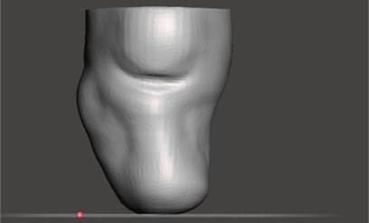
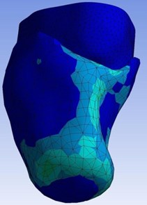
This study focused on developing a stump-socket model using a subject specific CT (Computed tomography) image. Next step is to convert the scan CT images which are in DICOM (Digital Imaging and communication in medicine) format to an nrrd (nearly raw raster data) file by using 3D Slicer software. By importing CT images folder into 3D Slicer software and save that file in nrrd format. Embodi3D is the free service that will convert the scan into a 3D printable model file and Converts an nrrd (nearly raw raster data) file to STL format. The stump was obtained using 3D Slicer and embodi3D image processing software. As shown in Fig. 1 is the stump model which is generated by reverse engineering technique.
Fig. 1Stump model
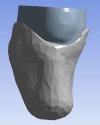
The stump model which is obtained is then imported into Meshmixer software. By using the design tools in Meshmixer created socket model with reference to stump model. The stump-socket models were imported into Solidworks for converting into solid model and assembled. The assembled model is later imported into ANSYS for simulation. As shown Fig. 2 below is geometry model of stump-socket.
Fig. 2Stump-socket CAD model
2.2. Material and material properties for the model
The parts of the materials assumed as isotropic at uniform manner at all principal directions with elastic properties. The parts to be assumed as homogenous with standard material properties. Soft tissues and skin of stump (prosthetic leg) were assumed as a mooney-rivlin material model. Various studies have reported soft tissue could be assumed as a viscoelastic material. By using strain-energy function behavior of viscoelastic for material model is obtained depending upon linear viscoelastic material. Normally any finite element model is characterized by its geometry, properties of the material used and some particular geometric perspectives such as proper boundary conditions and loading conditions. In this work a uniform temperature corresponding to the value ambient temperature i.e., 22 °C will be applied to the model. Stump is considered as Mooney-Rivlin model and socket was considered as acrylonitrile butadiene styrene (ABS). The mechanical properties for socket model as tabulated below in table 1.
Table 1Material properties of acrylonitrile butadiene styrene
Density | 1040 kg m-3 |
Isotropic Secant coefficient of thermal expansion | 0.0000954 C-1 |
Specific heat | 1720 Jkg-1C-1 |
Isotropic thermal conductivity | 0.258 Jm-1 s-1C-1 |
Poisson’s ratio | 0.399 |
2.3. Finite element analysis
By using Solidworks software the stump and socket assembled. Solid geometrical model generated in Solidworks software. The solid geometrical model imported into ANSYS for static structural analysis and explicit dynamics analysis. The simulation performed using ANSYS to simulate the behavior of the stump-socket interface. Static structural analysis and explicit dynamics analysis performed on stump-socket models interface stresses were measured and to study the mechanical behavior such as the total deformation and von-mises stress distribution under the given loading conditions.
2.4. Experimental setup
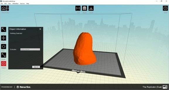
During the preparation of socket the comfort and flexibility of socket for patient is to be consider in order to reduce stress on the stump. For exactly fitting of socket to the patient stump is prepared by using 3D printing by printing technology of fused filament fabrication. Specification for the 3D printer for preparing socket is diameter for filament extruder is 1.75 mm, filament diameter is about 1.75+0.1 mm and operation temperature about 260 °C. This 3D printer is used for reduction cost for the patient socket. Socket is mainly prepared by the material acrylonitrile butadiene styrene. For this 3D printer Replicator G software is used for printing process in 3D printer. The 3D printer supports STL and g code files and print files upload through SD card or over USB devices. As shown in Fig. 3 is preparation setup of software for 3D printing.
Fig. 3Socket model in 3D printer
3. Results and discussion
3.1. Meshing and boundary conditions
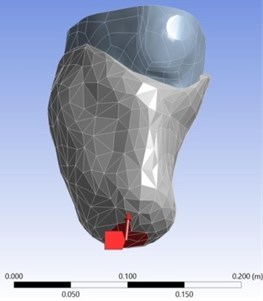
In workbench the mesh element used here is Hexagonal in nature and the size of the mesh (face mesh) is about 0.01 m. The number of nodes is 8144 whereas the number of elements is 29379. Now the loads have to be applied for the meshed volume. For simulation, the degrees of freedom (DOF) of one end of the socket is constrained and force of 500 N for static structural and velocity of 10 m/s for explicit dynamics were applied to the stump. In Fig. 4 as shown represents the direction of force applied in static structural.
Fig. 4Static structural force direction
3.2. Analysis type
Here Static analysis and explicit dynamic analysis were carried out to determine the deformation, stresses between stump and socket under the given loading conditions. The Static Structural analysis and explicit dynamics can be found in the software toolbox in Ansys software.
3.2.1. Static structural analysis
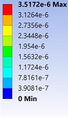
In static structural analysis force of 500 N is applied in direction towards stump as shown in Fig. 4. The extreme and lowest deformation of the prosthetic socket and stump model made of the acrylonitrile butadiene styrene and Mooney Rivlin model under the given boundary conditions was shown in the Fig. 5. The different colour indicates values of deformation as shown in left side portion of Fig. 5. In this static structural total deformation obtained maximum at 3.5172e-006 m due to maximum load acting at that portion of socket.
Fig. 5Total deformation of the stump-socket interface
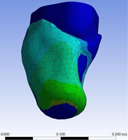
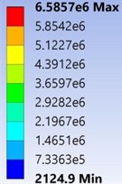
As shown in Fig. 6 the Von-Mises Stress of the stump-socket model made of the acrylonitrile butadiene styrene and Mooney-Rivlin model under the given boundary conditions. Minimum of von-mises stress was found to be 2124.9 Pa and maximum of von-mises stress was found to be 6.5857e+006 Pa respectively.
Fig. 6Von-Mises stress of the stump-socket interface
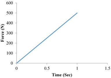
In static structural analysis graph plotted between force and time as shown in the Fig. 7. Force is linearly increased with increasing of time. The force 500 N maximum is obtained at time 1 sec. In the Fig. 7, the linear relationship is follow as increasing of force with an increase of time may slope constant.
Fig. 7Static structural analysis force vs time
3.2.2. Explicit dynamics analysis
In explicit dynamics analysis velocity of 10 m/s for were applied to the stump down towards the socket. The extreme and lowest deformation of the prosthetic socket and stump model made of the acrylonitrile butadiene styrene and Mooney Rivlin model under the given boundary conditions was found to be 0 m and 3.539e-002m respectively as shown in Fig. 8. Obtained total deformation maximum at 0.03539 m.
In Explicit dynamics analysis of total deformation graph is plotted between deformation and time. In Fig. 9, as Increasing of time the deformation also increasing linearly but deformation is slightly increase high at time period of 2.4e-03 to 3.0001e-02.
The extreme and lowest Von-Mises Stress of the stump-socket model made of the acrylonitrile butadiene styrene and Mooney-Rivlin model under the given boundary conditions as shown in Fig. 10. From the results observed that maximum obtain Von-Mises stress at 3.5893e5 Pa.
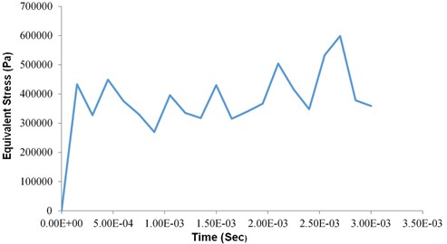
In Explicit dynamics analysis of total deformation graph is plotted between equivalent stress and time which is varying (Increasing and decreasing) along with the time as shown in Fig. 11.
Fig. 8Total deformation of the stump-socket interface
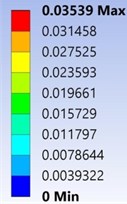
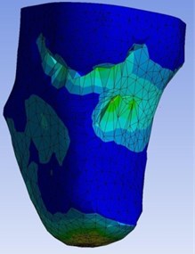
Fig. 9Dynamic structural analysis deformation vs time
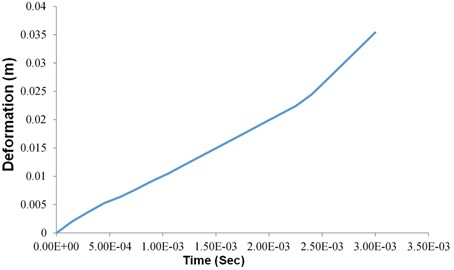
Fig. 10Von-Mises stress of the stump-socket interface
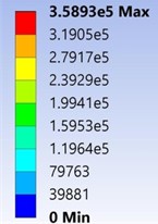
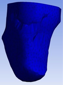
Fig. 11Dynamic structural analysis equivalent stress vs time
4. Experimental analysis
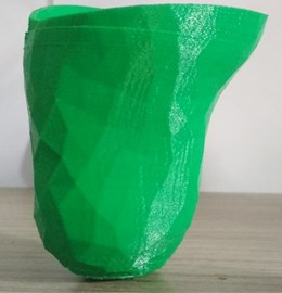
Preparing of socket by using 3D printer for the dimensional accuracy. It is the best process for simple, easy and takes less time for of making socket. In the experimental analysis power input for 3D printer is 220 V/110 V and output about 200 W. The layer thickness is about 0.1-0.5 mm (100 microns). Maximum extrusion temperature is 230 °C. , axis positioning resolution is about 0.02 mm and axis positioning resolution is 0.005 mm. The socket model is manufactured by using 3D printer by using material of acrylonitrile butadiene styrene as shown in the Fig. 12 below. Finally printed socket by using 3D printer as shown in Fig. 13.
Fig. 12Printing of socket on 3D printer
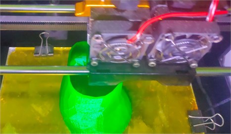
Fig. 13Final socket prepared by using 3D printing
5. Conclusions
The pressures exhibited tendency obtained from the results for both the static structural and explicit dynamics sockets were shown. The shape of the sockets ensures the behavior of the stump for every subject was mostly similar. Measurement differences of static structural analysis and explicit dynamics were observed. The reason is because of the period during which the subject wearing the socket. Due to reducing in elasticity of the muscle prosthetic socket user experiencing continuous fluctuations of shape and volume daily. The elasticity of the soft tissue reduction contributes to maximization of the tri-axial force. It was known according to the FEA, to the stump model remained acrylonitrile butadiene styrene with viscoelastic, homogenous and the elasticity. Acrylonitrile butadiene styrene is the material which is primarily used for the fabrication of the prosthetic socket was examined to study the consequence of materials on the mechanical behavior of the stump-socket interface under given loading conditions. In addition, with static structural analysis explicit dynamic analysis was also assessed to study the outcome of dynamic simulations. The results obtained manifest that the stump-socket interface has a significant impact on the deformation and von-mises stress between stump and socket.
References
-
“ISPO Triennium Report 2010-2013,” Brussels, International Society for Prosthetics and Orthotics, 2013.
-
C. C. Lyon, J. Kulkarni, E. Zimersonc, E. van Ross, and M. H. Beck, “Skin disorders in amputees,” Journal of the American Academy of Dermatology, Vol. 42, No. 3, pp. 501–507, Mar. 2000, https://doi.org/10.1016/s0190-9622(00)90227-5
-
S. W. Levy, “Skin problems of the leg amputee,” Prosthetics and Orthotics International, Vol. 4, No. 1, pp. 37–44, Apr. 1980, https://doi.org/10.3109/03093648009103113
-
A. Salawu, C. Middleton, A. Gilbertson, K. Kodavali, and V. Neumann, “Stump ulcers and continued prosthetic limb use,” Prosthetics and Orthotics International, Vol. 30, No. 3, pp. 279–285, Dec. 2006, https://doi.org/10.1080/03093640600836139
-
A. Gefen, B. van Nierop, D. L. Bader, and C. W. Oomens, “Strain-time cell-death threshold for skeletal muscle in a tissue-engineered model system for deep tissue injury,” Journal of Biomechanics, Vol. 41, No. 9, pp. 2003–2012, Jan. 2008, https://doi.org/10.1016/j.jbiomech.2008.03.039
-
W. C. C. Lee, M. Zhang, X. Jia, and J. T. M. Cheung, “Finite element modeling of the contact interface between trans-tibial residual limb and prosthetic socket,” Medical Engineering and Physics, Vol. 26, No. 8, pp. 655–662, Oct. 2004, https://doi.org/10.1016/j.medengphy.2004.04.010
-
X. Jia, M. Zhang, and W. C. C. Lee, “Load transfer mechanics between trans-tibial prosthetic socket and residual limb-dynamic effects,” Journal of Biomechanics, Vol. 37, No. 9, pp. 1371–1377, Sep. 2004, https://doi.org/10.1016/j.jbiomech.2003.12.024
-
X. Jia, M. Zhang, X. Li, and W. C. C. Lee, “A quasi-dynamic nonlinear finite element model to investigate prosthetic interface stresses during walking for trans-tibial amputees,” Clinical Biomechanics, Vol. 20, No. 6, pp. 630–635, Jul. 2005, https://doi.org/10.1016/j.clinbiomech.2005.03.001
-
D. Lacroix and J. F. Ramírez Patiño, “Finite element analysis of donning procedure of a prosthetic transfemoral socket,” Annals of Biomedical Engineering, Vol. 39, No. 12, pp. 2972–2983, Dec. 2011, https://doi.org/10.1007/s10439-011-0389-z
-
Linlin Zhang, Ming Zhu, Ling Shen, and Feng Zheng, “Finite element analysis of the contact interface between trans-femoral stump and prosthetic socket,” in 2013 35th Annual International Conference of the IEEE Engineering in Medicine and Biology Society (EMBC), Vol. 2013, pp. 1270–3, Jul. 2013, https://doi.org/10.1109/embc.2013.6609739
-
Jaime Andrés Vélez Zea, Liliana Marcela Bustamante Góez, and Junes Abdul Villarraga Ossa, “Relation between residual limb length and stress distribution over stump for transfemoral amputees,” Revista EIA, Vol. 12, No. 23, pp. 107–115, Jun. 2015.
-
S. G. Zachariah and J. E. Sanders, “Finite element estimates of interface stress in the trans-tibial prosthesis using gap elements are different from those using automated contact,” Journal of Biomechanics, Vol. 33, No. 7, pp. 895–899, Jul. 2000, https://doi.org/10.1016/s0021-9290(00)00022-1
-
G. M. Rommers, L. D. W. Vos, L. Klein, J. W. Groothoff, and W. H. Eisma, “A study of technical changes to lower limb prostheses after initial fitting,” Prosthetics and Orthotics International, Vol. 24, No. 1, pp. 28–38, Apr. 2000, https://doi.org/10.1080/03093640008726519
-
E. E. Haggstrom, E. Hansson, and K. Hagberg, “Comparison of prosthetic costs and service between osseointegrated and conventional suspended transfemoral prostheses,” Prosthetics and Orthotics International, Vol. 37, No. 2, pp. 152–160, Apr. 2013, https://doi.org/10.1177/0309364612454160
-
M. Lilja and T. Oberg, “Proper time for definitive transtibial prosthetic fitting,” Prosthetics and Orthotics International, Vol. 9, No. 2, pp. 90–95, 1997.
-
M. Lilja, P. Hoffmann, and T. Öberg, “Morphological changes during early trans-tibial prosthetic fitting,” Prosthetics and Orthotics International, Vol. 22, No. 2, pp. 115–122, Aug. 1998, https://doi.org/10.3109/03093649809164472
-
S. G. Zachariah, R. Saxena, J. R. Fergason, and J. E. Sanders, “Shape and volume change in the transtibial residuum over the short term: preliminary investigation of six subjects,” The Journal of Rehabilitation Research and Development, Vol. 41, No. 5, p. 683, 2004.
-
R. Gailey, “Review of secondary physical conditions associated with lower-limb amputation and long-term prosthesis use,” The Journal of Rehabilitation Research and Development, Vol. 45, No. 1, pp. 15–30, Dec. 2008, https://doi.org/10.1682/jrrd.2006.11.0147
-
S. H. Ibbotson, N. B. Simpson, N. C. M. Fyfe, and C. M. Lawrence, “Follicular keratoses at amputation sites,” British Journal of Dermatology, Vol. 130, No. 6, pp. 770–772, Jun. 1994, https://doi.org/10.1111/j.1365-2133.1994.tb03416.x
-
C. V. Bouten, C. W. Oomens, F. P. Baaijens, and D. L. Bader, “The etiology of pressure ulcers: skin deep or muscle bound?” Archives of Physical Medicine and Rehabilitation, Vol. 84, No. 4, pp. 616–619, Apr. 2003, https://doi.org/10.1053/apmr.2003.50038
-
H. Meulenbelt, J. Geertzen, P. Dijkstra, and M. Jonkman, “Skin problems in lower limb amputees: an overview by case reports,” Journal of the European Academy of Dermatology and Venereology, Vol. 21, No. 2, pp. 147–55, Feb. 2007, https://doi.org/10.1111/j.1468-3083.2006.01936.x
-
E. C. T. Baars and J. H. B. Geertzen, “A patient with donning-related stump wounds: A case report,” Prosthetics and Orthotics International, Vol. 32, No. 2, pp. 219–222, Jun. 2008, https://doi.org/10.1080/03093640802016738
-
R. Torres-Moreno, D. Jones, Se. Solomonides, and H. Mackie, “Magnetic resonance imaging of residual soft tissues for computer-aided technology applications in prosthetics – a case study,” Prosthetics and Orthotics International, Vol. 11, No. 1, pp. 6–11, 1999.
-
T. A. Krouskop, A. L. Muilenberg, D. R. Doughtery, and D. J. Winningham, “Computer-aided design of a prosthetic socket for an above-knee amputee,” Journal of Rehabilitation Research and Development, Vol. 24, No. 2, pp. 31–38, 1987.
-
S. G. Zachariah and J. E. Sanders, “Interface mechanics in lower-limb external prosthetics: a review of finite element models,” IEEE Transactions on Rehabilitation Engineering, Vol. 4, No. 4, pp. 288–302, 1996, https://doi.org/10.1109/86.547930
-
Sanders Je, Greve Jm, Mitchell Sb, and Zachariah Sg, “Material properties of commonly-used interface materials and their static coefficients of friction with skin and socks,” Journal of Rehabilitation Research and Development, Vol. 35, No. 2, pp. 161–76, Jun. 1998.
-
M. Zhang and A. F. T. Mak, “In vivo friction properties of human skin,” Prosthetics and Orthotics International, Vol. 23, No. 2, pp. 135–141, Aug. 1999, https://doi.org/10.3109/03093649909071625
-
S. Derler and L.-C. Gerhardt, “Tribology of skin: review and analysis of experimental results for the friction coefficient of human skin,” Tribology Letters, Vol. 45, No. 1, pp. 1–27, Jan. 2012, https://doi.org/10.1007/s11249-011-9854-y
-
J. F. Ramírez, J. J. Pavón, and A. Toro, “Experimental assessment of friction coefficient between polypropylene and human skin using instrumented sclerometer,” Proceedings of the Institution of Mechanical Engineers, Part J: Journal of Engineering Tribology, Vol. 229, No. 3, pp. 259–265, Mar. 2015, https://doi.org/10.1177/1350650114526579
-
M. Bliss, “How do microclimate factors affect the risk for superficial pressure ulcers: a mathematical modelling study,” Journal of Tissue Viability, Vol. 20, No. 4, p. 131, Nov. 2011, https://doi.org/10.1016/j.jtv.2011.08.001
-
E. Tonuk and M. B. Silver-Thorn, “Nonlinear elastic material property estimation of lower extremity residual limb tissues,” IEEE Transactions on Neural Systems and Rehabilitation Engineering, Vol. 11, No. 1, pp. 43–53, Mar. 2003, https://doi.org/10.1109/tnsre.2003.810436
-
S. Portnoy, I. Siev-Ner, Z. Yizhar, A. Kristal, N. Shabshin, and A. Gefen, “Surgical and morphological factors that affect internal mechanical loads in soft tissues of the transtibial residuum,” Annals of Biomedical Engineering, Vol. 37, No. 12, pp. 2583–2605, Dec. 2009, https://doi.org/10.1007/s10439-009-9801-3
-
J. T. Peery, W. R. Ledoux, and G. K. Klute, “Residual-limb skin temperature in transtibial sockets,” The Journal of Rehabilitation Research and Development, Vol. 42, No. 2, p. 147, 2005, https://doi.org/10.1682/jrrd.2004.01.0013
-
M. Clark, M. Romanelli, Si. Reger, Vk. Ranganathan, J. Black, and C. Dealey, “Micro – climate in context.,” in International Review: Pressure Ulcer Prevention: Pressure, Shear, Friction and Microclimate in Context, Wounds International, 2010.
-
W. Sae-Sia, D. D. Wipke-Tevis, and D. A. Williams, “Elevated sacral skin temperature (T(s)): a risk factor for pressure ulcer development in hospitalized neurologically impaired Thai patients,” Applied Nursing Research, Vol. 18, No. 1, pp. 29–35, Feb. 2005, https://doi.org/10.1016/j.apnr.2004.03.005
-
D. J. Atherton, “A review of the pathophysiology, prevention and treatment of irritant diaper dermatitis,” Current Medical Research and Opinion, Vol. 20, No. 5, pp. 645–649, May 2004, https://doi.org/10.1185/030079904125003575
-
L.-C. Gerhardt, V. Strässle, A. Lenz, N. D. Spencer, and S. Derler, “Influence of epidermal hydration on the friction of human skin against textiles,” Journal of The Royal Society Interface, Vol. 5, No. 28, pp. 1317–1328, Nov. 2008, https://doi.org/10.1098/rsif.2008.0034
-
D. M. Sengeh, K. M. Moerman, A. Petron, and H. Herr, “Multi-material 3-D viscoelastic model of a transtibial residuum from in-vivo indentation and MRI data,” Journal of the Mechanical Behavior of Biomedical Materials, Vol. 59, pp. 379–392, Jun. 2016, https://doi.org/10.1016/j.jmbbm.2016.02.020
-
D. P. Reynolds and M. Lord, “Interface load analysis for computer-aided design of below-knee prosthetic sockets,” Medical and Biological Engineering and Computing, Vol. 30, No. 4, pp. 419–426, Jul. 1992, https://doi.org/10.1007/bf02446180
-
J. C. H. Goh, P. V. S. Lee, S. L. Toh, and C. K. Ooi, “Development of an integrated CAD-FEA process for below-knee prosthetic sockets,” Clinical Biomechanics, Vol. 20, No. 6, pp. 623–629, Jul. 2005, https://doi.org/10.1016/j.clinbiomech.2005.02.005
-
G. Colombo, S. Filippi, C. Rizzi, and F. Rotini, “A new design paradigm for the development of custom-fit soft sockets for lower limb prostheses,” Computers in Industry, Vol. 61, No. 6, pp. 513–523, Aug. 2010, https://doi.org/10.1016/j.compind.2010.03.008
-
M. Javaid and A. Haleem, “Additive manufacturing applications in medical cases: A literature based review,” Alexandria Journal of Medicine, Vol. 54, No. 4, pp. 411–422, Dec. 2018, https://doi.org/10.1016/j.ajme.2017.09.003
-
M. Irfan Ul Haq et al., “3D printing for development of medical equipment amidst coronavirus (COVID-19) pandemic—review and advancements,” Research on Biomedical Engineering, pp. 1–11, Oct. 2020, https://doi.org/10.1007/s42600-020-00098-0
-
R. Aziz, M. I. Ul Haq, and A. Raina, “Effect of surface texturing on friction behaviour of 3D printed polylactic acid (PLA),” Polymer Testing, Vol. 85, p. 106434, May 2020, https://doi.org/10.1016/j.polymertesting.2020.106434
-
A. Chadha, M. I. Ul Haq, A. Raina, R. R. Singh, N. B. Penumarti, and M. S. Bishnoi, “Effect of fused deposition modelling process parameters on mechanical properties of 3D printed parts,” World Journal of Engineering, Vol. 16, No. 4, pp. 550–559, Jul. 2019, https://doi.org/10.1108/wje-09-2018-0329
Cited by
About this article

