Abstract
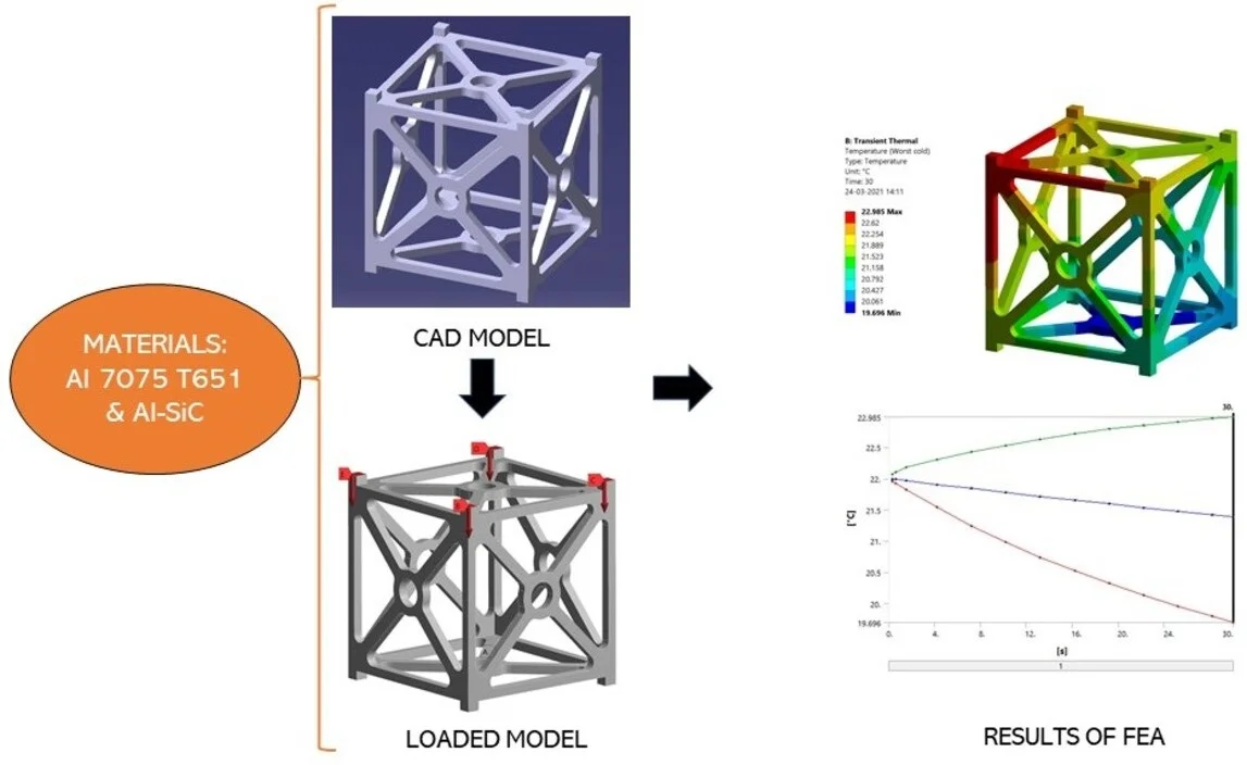
CubeSat is one of the trending technologies in the developed and developing countries across the globe. Various materials are used in the manufacturing of a CubeSat’s subsystems. Structural subsystem is an essential one for a CubeSat’s mission as it bears all the components, payload, and withstand space environment. Usually, aluminium alloys are used in the construction of outer structural frame. In this paper, Al-SiC metal matrix composite is analysed and compared with the conventional Al 7075 T651 alloy. Simulation is done with the help of ANSYS 19.2 software. A series of Static structural, Modal, and Transient thermal analysis is carried out on both materials. Al7075 T651 performed better in most cases. But also, Al-SiC showed good results in specific cases like lesser deformation, modal analysis at higher vibrations. Al-SiC could be combined with the existing aluminium alloys in the manufacturing of CubeSat’s structural frame for a better and efficient output in a specific environment.
Highlights
- CubeSat frame with two different materials has been analysed using Finite element analysis.
- Comparative results have been obtained for Al-SiC Metal Matrix Composite and Al 7075 T651 alloy.
- Pros and cons of both the materials in the manufacturing of CubeSat frame have been analysed.
1. Introduction
The development and usage of CubeSats for technical research and industrial purposes has been increased rapidly in recent years. CubeSats belong to the class of nano satellites. They are built in standard dimensions of Unit(U). 1U = 0.1 m × 0.1 m × 0.1 m (length × breadth × height). The 1U CubeSat usually weighs not more than 1.33 kg. A maximum of 12U CubeSat can be built with today’s technology [1]. The first CubeSat was developed in 1999 at California Polytechnic State University and Stanford University. Professors Jordi Puig-Suari and Bob Twiggs with their students designed a low-cost, low-mass satellite in space. A CubeSat has several components and subsystems. The main six subsystems of a CubeSat are structure, communication, power, attitude determination and control, command and data handling, and the payload. For the effective functioning of a CubeSat, all the subsystems and components should work properly [1].
Structure: CubeSats range in size from 1 U to 12 U. They are always 10×10 cm in length and width, but their height can vary from 0.1135 m to 1.362 m. The commonly used materials of the structure are Al 7075, 6061, 5005 and 5052, and they have to be anodized to avoid cold welding.
Communication: CubeSats use radio-communication systems in VHF, UHF, F-, S-, C- and X-band. The satellite uses an antenna for communication purposes. Antennas vary from measuring tape to more complex inflatable dish antennas.
Power: The electrical power system for CubeSats is provided by solar panels and batteries. Solar panels convert the sunlight from the sun into electricity.
Control: The attitude determination and control system (ADCS) control the orientation of the CubeSat with respect to an inertial frame of reference and it includes reaction wheels, magnetorquers, thrusters etc., [1].
Command and Data handling: The command and data handling system (CDHS) has their own computer which interfaces with the payload to do various tasks which might include image processing, data analysis, and data compression [1].
Payload: The payload varies from mission to mission. It depends on the application of the mission. These can include cameras for pictures or video, some sensors, and instruments to predict weather conditions and so on [1].
During the launch phase, a CubeSat’s structural frame must withstand certain loads and temperature. The CubeSat must remain functional after facing those external factors. So, the materials used in the construction of structural frame should be chosen wisely with several analysis and testing [1].
Usually, Aluminium alloys like Al 7075, Al T650, are used in the Construction the structural frame. Recent advances in composites, sandwiches, and metal matrix enabled the industries to manufacture several construction parts in the aerospace and aviation field.
Finite Element Analysis is widely used in the aerospace sector. Structural, vibrational analysis of wings, advanced analysis of morphed wings, and optimization of materials in the defense field are easily done using this approach. Leading aircraft manufacturers across the globe are using FEA method for initial planning and execution of any new and innovative design. A different approach of using Al-Sic metal matrix in the construction of CubeSat’s frame is discussed in this article. Also, the finite element analysis results of both Al-SiC and Al 7075 T651 alloy are compared and discussed. A series of Static structural, Modal and Transient thermal analysis of a CubeSat’s outer structural frame has been carried out using ANSYS software.
2. Materials and Methodology
2.1. Al-SiC Metal Matrix composite
Metal matrix composite (MMC) consists of reinforcing particles with a metal matrix phase. Usually, low density materials such as aluminium, magnesium, titanium are used as metal matrix. Al-SiC is a metal matrix composite which has aluminium as the metal matrix and silicon carbide as the reinforcement particle. The Al-SiC Metal Matrix Composites find their application in many industrial products due to their unique properties such as light weight, high strength, high specific modulus, high fatigue strength, high hardness, and low density. Rheo-process, compo-casting are some of the widely using processing techniques for this composite [2]. Fig. 1 shows some mechanical components manufactured using Al-SiC.
Fig. 1Some mechanical components manufactured using Al-SiC [3]
![Some mechanical components manufactured using Al-SiC [3]](https://static-01.extrica.com/articles/22047/22047-img1.jpg)
2.1.1. Properties of Al-SiC
Table 1 describes the mechanical and thermal properties of the 56 % volume fraction of Al- SiC composite. Because of its significant thermal properties and composite features, Al-SiC is used as the packaging material for high technology thermal management [2].
2.2. Al 7075 T651 alloy
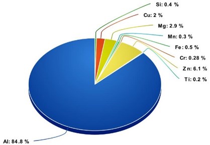
Al 7075 T651 is an aluminum alloy, in that the primary alloying element id Zinc. It exhibits good ductility, toughness, high strength, and good resistance to fatigue. Al-7075 alloy was first used in the Mitsubishi A6M Zero fighter. This aircraft had excellent maneuverability which was achieved by the higher strength of Al 7075 compared to previously used aluminum alloys. It finds its application in gears and shafts, aircraft fittings, regulating valve parts, missile parts and worm gears etc., [4] Fig. 2 shows the chemical composition of Al 7075 T651 alloy.
Table 1Properties of Al-SiC MMC [2]
Density (kg/m3) | 2940 |
Young’s modulus (MPa) | 220000 |
Poisson ratio | 0.23 |
Maximum yield stress (MPa) | 43.68 |
Coefficient of thermal expansion (1/°K) | 8×10⁻⁶ |
Thermal conductivity (W/mK) | 235 |
Specific Heat (J/kgK) | 919 |
Fig. 2Chemical composition Al 7075 T651 alloy
2.2.1. Properties of Al 7075
The mechanical and thermal properties of Al 7075 T651 alloy are listed in the Table 2.
Table 2Properties of Al 7075 T651 alloy [4]
Density (kg/m3) | 2810 |
Young’s modulus (MPa) | 71700 |
Poisson ratio | 0.33 |
Maximum Yield Stress (MPa) | 503 |
Coefficient of thermal expansion (1/°K) | 23.6×10⁻⁶ |
Thermal conductivity (W/mK) | 130 |
Specific Heat (J/kgK) | 960 |
2.3. CAD modelling
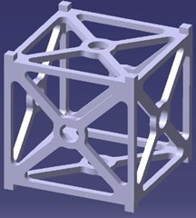
The CubeSat frame is designed in CATIA V5 software. CATIA is a multi-platform software suitable for computer-aided design (CAD), computer-aided manufacturing (CAM), computer-aided engineering (CAE), PLM and 3D, developed by the French company Dassault Systèmes. The model is designed in part design section of CATIA V5. The frame is designed with the dimensions of 0.1 m in length, 0.1 m in breadth, and 0.11 m in height. The thickness of frame is 0.04 m. The final CAD is shown in Fig. 3.
2.4. Finite element analysis
Finite Element Analysis (FEA) is the simulation of a physical model using numerical mathematical equations referred to as the Finite Element Method (FEM). Engineers use FEM to reduce the production of physical prototypes and run computational analysis to optimize their designs. Partial differential equations are used to analyze most of the cases in FEM, but in some complex cases, multiple higher order equations are implemented. Finite Element Analysis is the primary computational analysis technique in industries [5]. Finite element analysis is used for predicting the reaction of a product to real forces, heat, vibration, fluid flow, and other physical effects. Its results will declare whether a product will break, wear out, or work the way it was designed [5].
ANSYS 19.2 software is used here to run and visualize the results of finite element analysis of a CubeSat’s structural frame. The CAD model was converted to IGS file and imported to ANSYS Design modeler. For predicting the effective functioning of the two materials, three types of analysis have been carried out, i.e., Static structural analysis, Modal analysis, and transient thermal analysis.
Fig. 3CAD model of CubeSat’s frame
2.4.1. Static structural analysis
Structural analysis is the estimation of the effects of loads on constructed prototypes, structures, and their components. It employs the equations of mechanics, material science, and mathematics to simulate a product's total, equivalent and directional deformations, stresses, strains, and reactions developed etc., The results of the analysis are used to determine a product’s eligibility for industrial and general usage. A CubeSat’s outer frame undergoes static and dynamic loads. In this article, only Static case is discussed and analyzed [6].
The equations used in the Structural analysis:
where, is an array of applies loads, is matrix of stiffness, and is an array of displacements. Since, the values of and are known, the value of can be obtained by the matrix inversion method [6]:
2.4.2. Modal analysis
Modal analysis is the study of the vibration and dynamic properties of a mechanical product or a component in the frequency domain. Natural mode shapes and natural frequencies of an object can be determined using this modal analysis. Different shapes taken up by a structure during vibration can be visualized through modal analysis. Every object has a resonant frequency at which the vibration of the object occurs naturally. As the frequency increases towards this resonant frequency, the amplitude of response increases asymptotically to infinity. Eigensystems are the system of equations which arise from the modal analysis. An Eigensystem comprises of many eigen values and eigen vectors which represents frequencies and corresponding mode shapes [7].
Finite element analysis Eigensystems: For linear elastic material which obeys Hooke’s law, the equations take the form of a dynamic three-dimensional spring mass system [7].
The generalized equation of motion:
where, is mass matrix, is acceleration, is damping matrix, is stiffness matrix, and is force vector.
The damping is generally ignored for vibrational modal analysis. So, the second term in the above equation is neglected:
This is the common form of the eigensystem used in structural engineering using the finite element method. This equation can be further reduced to:
For free-vibration solutions, harmonic motion is assumed. Hence, is taken as , where is an eigenvalue. The equation for static problems:
This is applicable when the terms having a derivative of time are assigned to zero. The natural frequencies and mode shapes are the most significant properties of all mechanical and structural systems. For a better functioning of a mechanical system, the natural frequencies should be much larger than any excitation frequency that the system would probably face [8].
2.4.3. Transient thermal analysis
Thermal analysis is an analytical tool in the branch of materials sciences. Accurate thermal properties of materials at fixed or varying temperature can be determined through this analysis. Transient thermal analysis determines the response of a system which undergoes fixed and varying boundary conditions over time.
The elementary equation used in the Thermal analysis:
where, is the matrix of heat capacitance, is matrix of conductive heat coefficient, is matrix of convective heat coefficient, is an array of heat flux across the boundary, is an array of heat generation, and is an array of convective heat flux [9].
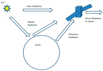
A CubeSat must work effectively in varying and hard space environment. There are three major thermal radiations which will be faced by a CubeSat:
– Radiation from the Sun,
– Albedo effect of the Earth,
– Infrared radiation from the Earth.
Satellites in the low earth orbit have to experience the temperature of range, –80 to +100 degree Celsius (approximately). In addition to this, conduction also occurs. The components of a satellite themselves emit certain amount of heat while consuming electrical energy from batteries.
The thermal load of direct solar flux acts on three faces, albedo effect acts on two faces and the earth’s infrared radiation acts on two faces. The satellite also emits radiation because of its temperature from its outer surfaces. To bear the payload properly in space, a structure should withstand maximum temperature [9]. Refer Fig. 4 for better understanding of thermal loads.
Fig. 4Thermal loading on a satellite
The equation used in the Transient thermal analysis:
where, is the matrix of conduction, is the matrix of radiation, is the matrix of heat capacity, is an array of heat loads. The solar radiation, albedo, and the infrared radiation are expressed in terms of heat flux. Heat flux () is the rate of heat energy transfer through a given surface (), and heat flux density () is the heat flux per unit area (W/m²) [9].
3. Results and discussion
The CAD model is imported to ANSYS 19.2 software. Unstructured triangular element type grid system is generated for this analysis. Mesh sensitivity analysis was made, and the results are described in Table 3. Span angle center is set as fine. Mesh refinement and face sizing are applied. The boundary conditions are given for all the three types of analysis. The results are post processed and discussed.
Fig. 5Meshed wireframe of CAD model
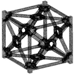
Table 3Results of Mesh Sensitivity test
Element size (m) | Number of elements | Number of nodes | Von mises stress (MPa) |
1e-4 | 101935 | 209062 | 5.5308 |
2.5e-4 | 70839 | 147085 | 5.5376 |
5e-4 | 29197 | 61346 | 5.5249 |
Mesh sensitivity analysis was made with three varying mesh element sizes of 1e-4 m, 2.5e-4 m, and 5e-4 m (0.1 mm, 0.25 mm, and 0.5 mm) for the case of CubeSat with Al-SiC material. The Equivalent stress (Von-Mises stress) is chosen for comparing the results of different mesh. The results obtained are good with minor variations. The output of the solution is independent of its grids count. Finally, the finest Mesh with 209062 computational nodes and 101935 elements is considered for the analysis which is depicted as Fig. 5 above.
3.1. Static structural analysis
A CubeSat’s frame has to withstand 50 load ( 9.8 m/S2) in an average. Therefore, the loads are applied on the upper part of the four rails and the bottom part of the rails is fixed. Since, the bottom part is usually in contact with the P-Pod (spring-loaded deployment mechanism). The simulation is done in the case when the CubeSat’s bottom part is clamped with the P-Pod and the loads are applied on the top part (-direction). The analysis has been carried out for both the materials. i.e., Al 7075 T651 alloy and Al-SiC metal matrix [10].
Fig. 6Static structural analysis results of Al 7075 T651
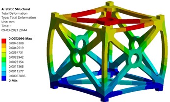
a) Total deformation – Al7075 T651
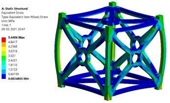
b) Equivalent stress created – Al 7075 T651
Fig. 6(a) and (b) show the simulated results for Al 7075 T651 alloy. The contours of total deformation and equivalent stress are obtained. As per the results, the maximum value of total deformation is 5.2e-6 m (0.0052 mm) and the value of maximum equivalent stress created is 5.446 MPa. The maximum yield stress of Al 7075 T651 is 503 MPa. Thus, the factor of safety is obtained as follows: 503/5.446 = 92.36.
Fig. 7(a) and (b) show the simulated results for Al-SiC metal matrix. The contours of total deformation and equivalent stress are obtained. As per the results, the maximum value of total deformation is 1.7e-6 m (0.0017 mm) and the value of maximum equivalent stress created is 5.531 MPa. The maximum yield stress of Al-SiC is 43.68 MPa. Thus, the factor of safety is obtained as follows: 43.68/5.531 = 7.90.
Fig. 7Static structural analysis results of Al-SiC
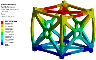
a) Total deformation – Al-SiC
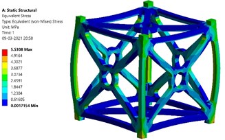
b) Equivalent stress created – Al-SiC
Comparing the results, Al 7075 T651 has higher value of factor of safety. On the other hand, Al-SiC has lesser value of total deformation.
3.2. Modal analysis
The design of the primary and secondary structures should ensure that their fundamental frequencies are satisfying the minimum values set by the launchers, by a good margin. The launching vehicle for this CubeSat is assigned as Polar Satellite Launch Vehicle (PSLV). The excitation frequency of the Polar Satellite Launch Vehicle is 100 Hz. As per the experimental data of Polar Satellite Launch Vehicle, the lowest natural frequency of the entire system must be greater than its excitation frequency (100 Hz). Modal analysis is done for first six modes and its corresponding deflections are also obtained [11].
Table 4Details of modal analysis
Type of analysis | Undamped |
Contact modelling | No |
Mode extraction method | Block Lanczos |
Number of modes extracted | 6 |
Table 4 shows the input details applied before performing Modal analysis. Undamped natural modes of the system are obtained. Block Lanczos mode extraction method is used as it can be implemented for its quicker convergence characteristics, and also it is suitable for symmetric cases. As this model consists of only one component i.e., chassis, and no other interference of geometries, contact modelling is not applied.
Fig. 8Results of modal analysis – Al 7075 T651
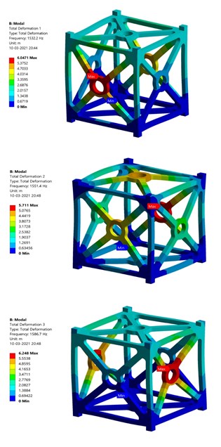
a) Al 7075 T651 – Modes 1, Mode 2, Mode 3 (Top, Middle, Bottom)
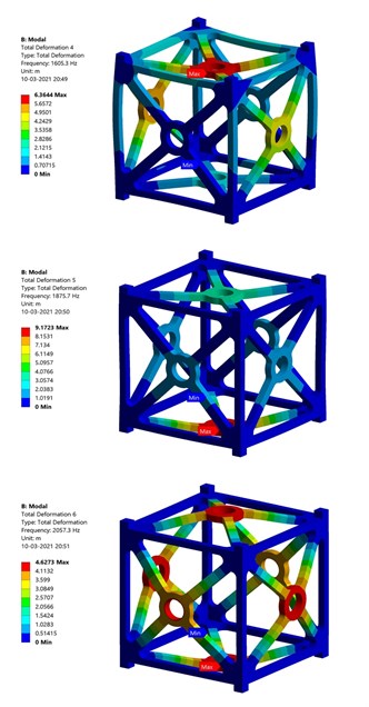
b) Al 7075 T651 – Modes 4, Mode 5, Mode 6 (Top, Middle, Bottom)
According to the specifications of launch vehicle, all the natural frequencies of both materials are greater than the excitation frequency of launch vehicle (100 Hz). Therefore, the CubeSat will not resonate easily. The first modal frequency of Al 7075 T651 is 1532.2 Hz and Al-SiC is 2620.1 Hz. Fig. 8 and Fig. 9 show the contours of Total deformation during modal analysis.
Fig. 9Results of modal analysis – Al-SiC
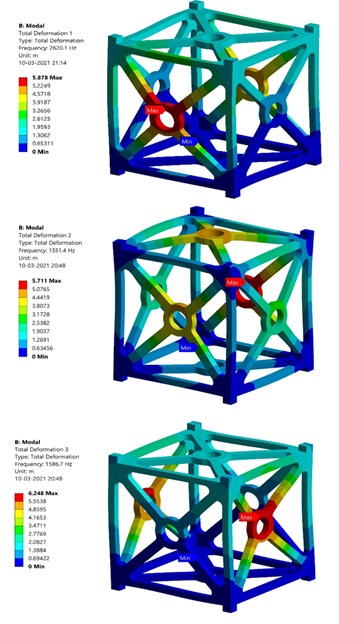
a) Al-SiC – Modes 1, Mode 2, Mode 3 (Top, Middle, Bottom)
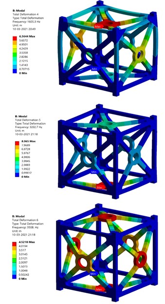
b) Al-SiC – Modes 4, Mode 5, Mode 6 (Top, Middle, Bottom)
Table 5 shows the first six natural frequencies of both Al 7075 T651 and Al-SiC. Al-SiC exhibits higher frequency in all the six modes than Al 7075 T651.
Table 5Natural frequencies at first six modes – Al 7075 T651 & Al-SiC
Mode | Frequency of Al 7075 T651 (Hz) | Frequency of Al-SiC (Hz) |
1 | 1532.2 | 2620.1 |
2 | 1551.4 | 2656.2 |
3 | 1586.7 | 2714.0 |
4 | 1605.3 | 2748.3 |
5 | 1875.7 | 3202.7 |
6 | 2057.3 | 3508.0 |
3.3. Transient thermal analysis
The CubeSat’s structure should withstand certain amount of solar radiation, infrared radiation, and albedo effect. These three external heat fluxes are applied on the six faces of the CubeSat. The internal temperature of the CubeSat is set as 298.15 K (25 °C). Table 6 shows the boundary conditions given for transient thermal analysis. Analysis is done for both worst hot and worst cold orbital conditions. At worst hot case, 35 % of the solar energy (497 W/m2) is reflected as albedo to the atmosphere by the earth. At worst cold case, 30 % of the solar energy (386.1 W/m2) is reflected as albedo to the atmosphere by the earth. The thermal loads are transferred to static structural mode to obtain the values of equivalent thermal stress [9].
Table 6Heat fluxes at worst hot and cold case, applied on outer faces of CubeSat’s structure [9]
Source of Heat flux | Worst hot (W/m2) | Worst cold (W/m2) | Number of faces applied on |
Solar radiation | 1420 | 1287 | 3 |
Earth’s Infrared | 249 | 227 | 2 |
Albedo | 497 | 386.1 | 2 |
The transient period is set as 30 seconds for this analysis and worst orbital conditions are applied in this analysis. Fig. 10 shows the transient thermal analysis results of Al 7075 T651 alloy. From the results, it is found that the maximum temperature which can be withstood by Al 7075 T651 alloy at worst hot case is 296.964 K (23.814 °C) and at worst cold case is 296.476 K (23.326 °C). The thermal stress produced at worst hot case is found to be 1.295 MPa. The thermal stress produced at worst cold case is found to be 1.186 MPa.
Fig. 10Transient thermal analysis results of Al 7075 T651
a) Temperature at worst hot case – Al 7075 T651
b) Temperature at worst cold case – Al 7075 T651
c) Thermal stress at worst hot case – Al 7075 T651
d) Thermal stress at worst cold case – Al 7075 T651
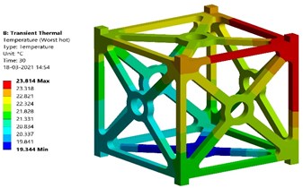
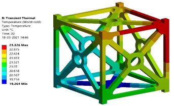
Fig. 11Magnitudes of temperature at worst hot and cold cases – Al-SiC
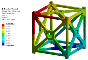
a) Temperature at worst hot case – Al-SiC
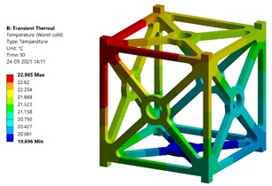
b) Temperature at worst cold case – Al-SiC
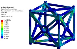
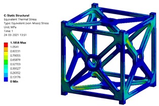
Fig. 11 and Fig. 12 show the transient thermal analysis results of Al-SiC metal matrix composite. In the case of Al-SiC composite, the maximum temperature which can be withstood at worst hot case is 296.586 K (23.436 °C) and at worst cold case is 296.135 K (22.985 °C). The thermal stress produced at worst hot case is found to be 0.60499 MPa. The thermal stress produced at worst cold case is found to be 0.55557 MPa.
The factor of safety of Al 7075 T651 based on the values of maximum thermal stress can be obtained as: At worst hot conditions, 503/1.295 = 388.41. At worst cold conditions, 503/1.295 = 424.11. The factor of safety of Al-SiC based on the values of maximum thermal stress can be obtained as: At worst hot conditions, 43.68/0.60499 = 72.199. At worst cold conditions, 43.68/0.55557 = 78.62. Comparing the numerical results, Al 7075 T651 alloy’s performance is good at worst hot condition with better factor of safety at both worst hot and cold conditions. Al-SiC composite shows better performance at worst cold condition.
Fig. 12Magnitudes of thermal stress at worst hot and cold cases – Al-SiC
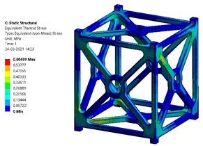
a) Thermal stress at worst hot case – Al-SiC
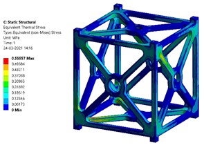
b) Thermal stress at worst cold case – Al-SiC
This work could be also validated with the experimental research carried out by Cui Yan et al. in 2008, “Multi-functional SiC/Al Composites for Aerospace Applications”, with the same range of specimen volume fraction which emphasizes the practical feasibility and manufacturing of aerospace structures using Al-SiC metal matrix composite [2].
4. Conclusions
In this paper, finite element analysis has been carried out to simulate and compare the performance of two different materials for the manufacturing of CubeSat’s structural frame. The primary three analysis (Structural, Modal and Thermal) has been carried out with specified boundary conditions with the help of ANSYS 19.2 software. The weight of empty frame when it is made of Al 7075 T651 is 0.2 kg, while with Al-SiC, it weighs 0.2 kg. Thus, Al-SiC weighs little more than Al 7075 T651.
From the results of Static structural analysis, it is clear that Al-SiC has better performance during deformation than Al 7075 T651. On the other hand, Al 7075 T651 has lesser von-Misses stress (Equivalent stress) production and better factor of safety than Al-SiC. This is obviously due to the fact that Al 7075 T651 has higher yield stress than Al-SiC. Since, Al-SiC has least total deformation value, it could be used in some specific portions of the structural frame in a certain amount. From the results of Modal analysis, it is obtained that Al-SiC shows higher value of natural frequencies in all the six modes than Al 7075 T651. So, the structure will not resonate easily if Al-SiC is used.
From the results of Transient thermal analysis, it is observed that Al 7075 T651 performs better at worst hot conditions while Al-SiC performs better at worst cold conditions. Thermal stress formation is found to be lesser in Al-SiC than in Al 7075 T651. But the value of factor of safety based on thermal loads is found to be higher in Al 7075 T651.
Validating the results of simulation, it is found that Al 7075 T651 exhibits better structural and thermal properties. Also, Al-SiC shows better outputs than Al 7075 T651 in certain cases such as lesser total deformation, higher natural frequency, and lesser formation of thermal stress.
So, Al-SiC could also be used in specific portions of the frame to obtain better efficiency in specific conditions. CubeSat is a trending technology around the global research community. So, future works can be done by developing this research work including many other analyses such as harmonic analysis, acoustic analysis, and simulation with electronic components etc.
References
-
T. Hatch. “Satellite 101: What is a CubeSat?,” https://tinyurl.com/66zz86eu, 2016.
-
C. Yan, W. Lifeng, and R. Jianyue, “Multi-functional SiC/Al composites for aerospace applications,” Chinese Journal of Aeronautics, Vol. 21, No. 6, pp. 578–584, Dec. 2008, https://doi.org/10.1016/s1000-9361(08)60177-6
-
“Aluminum-silicon carbide advanced substrate,” http://www.alphamaterials.com/alsic.htm
-
C. C. Bsgüvenç, B. C. Bstopcu, and C. Tola “Mechanical design and finite element analysis of a 3 unit cubesat,” International Scientific Journal, International Scientific Journal Machines, Technologies, Materials, Vol. 12, No. 5, pp. 193–196, 2018.
-
Autodesk. “Finite element analysis software,” https://www.autodesk.com/solutions/finite-element-analysis
-
M. A. Guler. “Chapter 4. Static Structural Analysis,” Workbench – Mechanical Introduction 12.0, http://mguler.etu.edu.tr/wb-mech_120_ch04_static.pdf
-
A. Harish. “What Is Modal Analysis and Why Is It Necessary?,” https://www.simscale.com/blog/2016/12/what-is-modal-analysis/
-
Jinbao Chen, Hong Nie, Zemei Zhang, and Lichun Li., “Finite element linear static structural analysis and modal analysis for Lunar Lander,” Journal of Vibroengineering, Vol. 16, No. 1, pp. 399–406, 2014.
-
A. Lahrichi, “Heat transfer modeling and simulation,” M.Sc. Thesis, School of Science and Engineering-Al Akhawayn University, 2017.
-
Kudzanai Sekerere and Tawanda Mushiri, “Finite element analysis of a CubeSat,” in Proceedings of the 2017 International Conference on Industrial Engineering and Operations Management, pp. 115–121, 2017.
-
Srikanth Raviprasad and S. Nagaraj Nayak, “Dynamic analysis and verification of structurally optimized nano-satellite systems,” Joural of Aerospace Science and Technology, Vol. 1, No. 2, pp. 78–90, Apr. 2015, https://doi.org/10.17265/2332-8258/2015.02.005
About this article

