Abstract
Knee joint is the most important and complex structure in human lower limbs. It is a nonlinear, time-varying and strong coupling system. In this paper, the mechanical structure of prosthetic knee joint is built, and parallel control of CMAC and PID algorithm is introduced to establish the knee joint control model. Through the simulation analysis, it is found that CMAC-PID control algorithm compared with the traditional PID control can improve the real-time and accuracy of the system. Therefore, CMAC-PID control algorithm can optimize the control effect of the prosthetic knee.
Highlights
- A four-bar mechanism was used as the moving part of the prosthesis knee joint, and the parameters of the knee joint were optimized with the instantaneous center of rotation (ICR) as the objective.
- The mechanical structure of prosthetic knee joint is designed and its CAD view with the components and materials are provided.
- A CMAC-PID control system is used for prosthetic knee joint. The simulation results show that the effect of the control system is better than traditional PID control.
1. Introduction
According to the results of previous investigations, the number of lower-limb disabled people in China is very large, so lower-limb medical AIDS have gradually attracted people's attention. The mechanism should not only be able to realize the basic functions of knee joint, but also have a good appearance and social recognition [1]. Therefore, a variety of knee joint models have been proposed, which can be divided into passive type and active type according to the drive mode. The passive type is a pure mechanical structure that relies on the wearer's power to control the knee movement, while the active type carries a microprocessor and driving device, which can power the movement of the knee. This paper aims to design an active prosthetic knee joint, which will provide the wearer with the torque required for the knee to achieve more complex actions.
Inevitably, response speed and accuracy of knee joint is required in the normal gait of human body. If your knees react too slowly, it is hard to keep your balance and walk smoothly, and if your knees don’t rotate into the right position in time, you can fall. Cerebellar model articulation controller (CMAC) is a kind of tabular query adaptive neural network expressing complex nonlinear function and changes the contents of the table through learning algorithm. The trajectory of healthy human knee joint is usually nonlinear, while CMAC can learn any multi-dimensional nonlinear mapping and is insensitive to the order of learning data. At the same time, CMAC is a neural network based on local learning, which has a very fast learning speed and is suitable for real-time control under the premise of guaranteeing the nonlinear approximation performance of the function [2]. In this paper, the knee joint mechanism is designed, and CMAC and PID parallel control algorithm [3] are adopted to optimize the knee joint control system.
2. Mechanical design of knee prosthesis
2.1. Calculation of mechanism parameters
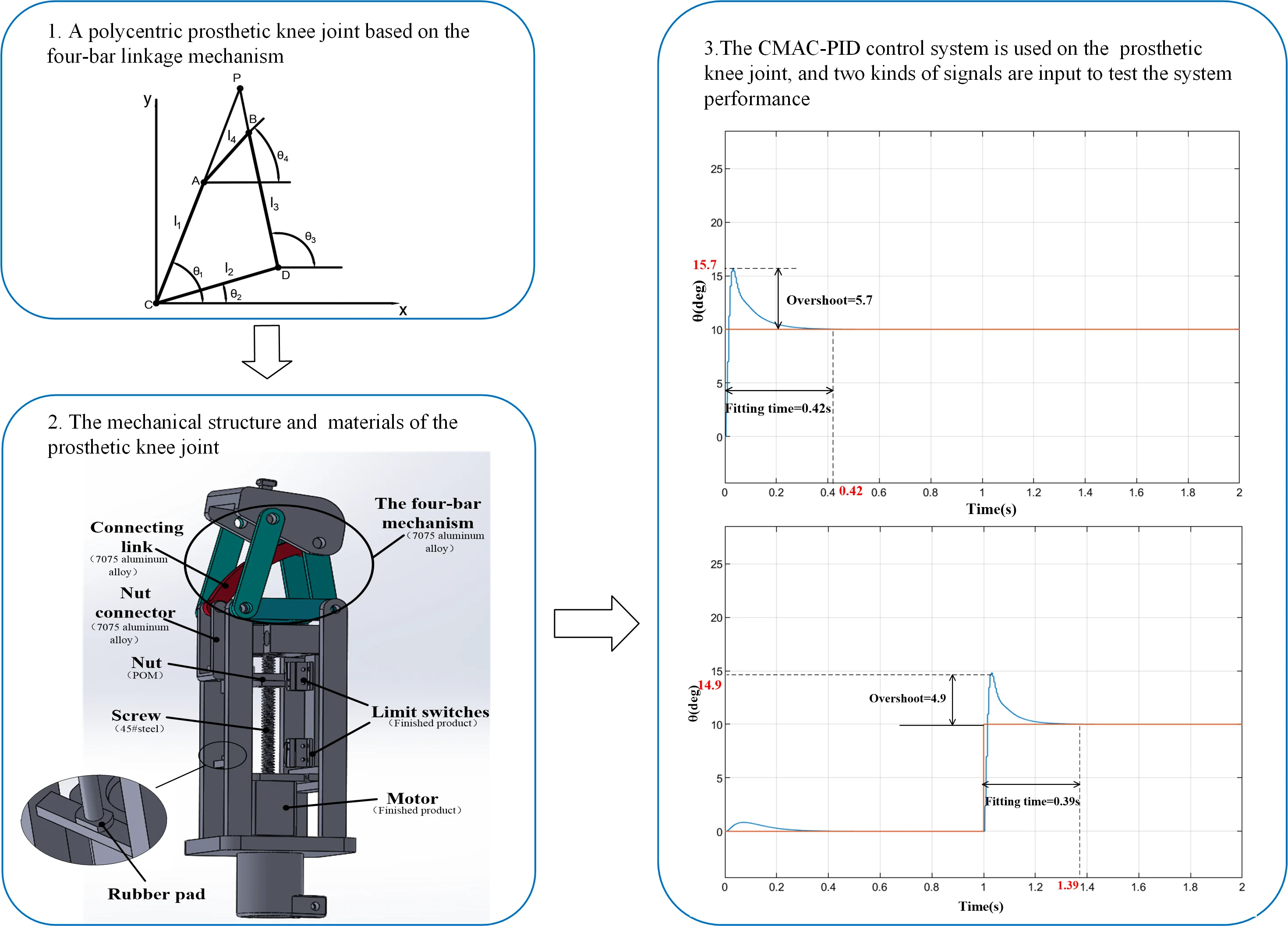
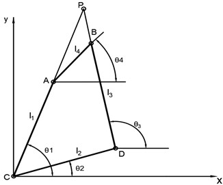
The types of prosthetic knee joints can be classified according to the number of rotational axes which determine the effect of knee motion. The prosthetic knee joint with single axis, although which can basically achieve gait movement, the ability of wearers to stand steadily and avoid obstacles is weak. Compared with the uniaxial prosthetic knee joint, the trajectory of the multiaxial prosthetic knee joint is closer to that of healthy human knee joint [4], and it can maintain a stable standing and swing flexibly. The best compromise solution considering cost, functionality and aesthetic aspect is a polycentric prosthetic joint based on the four-bar linkage mechanism which is widely described in literature for prosthetic applications [5]. Therefore, a four-bar prosthetic knee joint mechanism is designed in this paper. The following is the kinematic analysis of the mechanism, and the schematic diagram of the mechanism is drawn, as shown in Fig. 1.
Fig. 1Four-bar mechanism diagram
For the convenience of reading, the nomenclature of the symbols involved in the mechanism is listed in Table 1.
Table 1Symbol nomenclature of the mechanism
Symbol | Meaning |
, , , | The hinge connections of the four-bar mechanism |
, , , | The length of each link of the four-bar mechanism |
, , , | The angle of each link to the horizontal plane of the four-bar mechanism |
The instantaneous center of rotation (ICR) of the knee joint |
In the figure, the hinge connection of the four-bar mechanism is represented by four points , , and . Point is used as the origin to establish the Cartesian coordinate system. The lengths of four bars 1, 2, 3, 4 is expressed by , , , respectively, and the angle corresponding to the horizontal plane is , , , . Bar 4 is connected with the thigh stump socket, and bar 2 is connected with the mechanism of the lower leg. Point is the instantaneous center of rotation (ICR) of the knee joint. As is shown in the Fig. 1, the relationship between the four-bar mechanism can be obtained:
The above equation is computed and simplified to obtain the following [6]:
In the equation:
Thus, the relationship between the coordinates of points , , and the above variables can be obtained:
Let the coordinate of point be (), and according to the slope relation of the line, we can get:
After sorting out, the relationship between the coordinates of point and points , , is obtained:
By calculating the above equations, the relationship between point and the length of four bars and can be obtained. is the initial position angle of the mechanism. Then, these variables will be optimized to obtain the most appropriate mechanism parameters. is tentatively set as , and a vector with the lengths of four bars as the parameter is established:
According to previous conclusions, the flexion angle range of knee joint is approximately 0° to 110°. In the reference [7], researchers have measured the ideal coordinates of the ICR of knee joint, and then the objective function of optimization of four-bar mechanism is established as follows [8]:
where and are the coordinates of the ICR of the designed four-bar mechanism, and and are the coordinates of the ideal ICR of the knee joint.
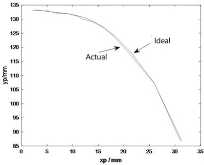
According to the kinematics and physiological conditions of the four-bar mechanism, constraints were established, and a functional model was built to optimize the parameters. The optimal results of the four-bar length and were obtained: 58.77 mm, 48.98 mm, 49.65 mm, 33.57 mm, 25.50°. Then, based on these parameters, a model was established for simulation [9], and the simulated trajectory of the ICR of the four-bar mechanism is finally obtained, as shown in the Fig. 2. Root mean square error (RMSE) is a commonly used measure of the difference between values. The specific numerical values on the ICR of prosthesis knee joint and ideal knee joint are calculated, and the RMSE of them is about 2.7092 mm. In theory, the error between prosthesis knee and ideal knee is small. As can be seen from Fig. 2, the trajectory of the optimized mechanism’s ICR is very close to that of the ideal knee joint, indicating the mechanism can simulate the motion of human’s knee joint well.
Fig. 2Ideal ICR and actual ICR trajectory
2.2. The mechanical structure of the prosthetic knee
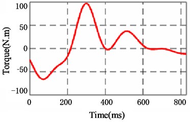
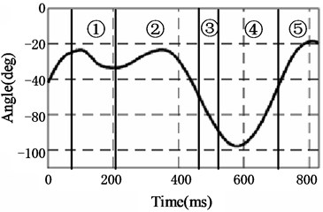
In order to simulate the motion of human knee joint, the relationship between knee angle and torque in a gait cycle is acquired. As is shown in Fig. 3, the graph at the top is the torque of the knee and the graph below it is the angular variation of human’s knee joint in a gait cycle. In the angle-time graph, the graph is divided into five parts: part 1 is response to weight and support; part 2 is final support; part 3 is initial swinging; part 4 is intermediate swinging; part 5 is final swinging. These parts represent the states of the knee joint during a gait cycle, and the torque corresponding to each state can also be known from the graph [10].
Fig. 3Knee angle and torque for one gait cycle
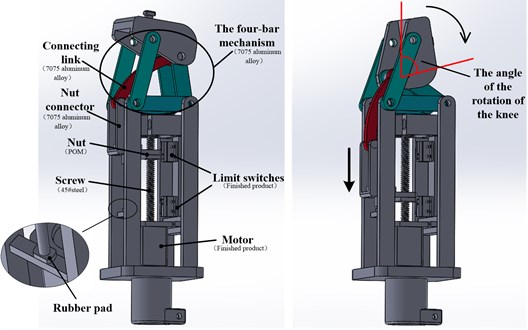
According to the above calculation and analysis, the CAD view of mechanical design of the prosthetic knee is shown in Fig. 4. The knee joint can rotate 100 degree which is enough for walking, sitting, and going upstairs. The rotation of the knee joint is provided by a lead screw driven by a motor. The nut, nut connector and connecting link are joined together to transfer the force from the nut to the four-bar mechanism. When the motor starts and the nut moves down, the four-bar mechanism carries out corresponding structural changes, and the rotation angle of the prosthetic knee joint increases. Two limit switches are installed on the mechanical structure, which will automatically cut off the motor once the nut reach the upper and lower limit positions.
The names of some parts of the prosthetic knee joint and their materials are marked in the CAD drawing. Except for those marked in the drawing, other parts are made of aluminum alloy (7075). Compared to other metal materials, aluminum alloy has many excellent properties, such as high strength, good wear resistance, corrosion resistance and oxidation resistance. In the same volume, aluminum alloy has the characteristics of low density and light weight, which can be used as a prosthetic material to reduce the burden of the wearer. Some rubber pads are also installed on the mechanical structure as shown in the enlarged part of Fig. 4. Rubber material presents unique viscoelastic properties, and has good shock absorption, sound insulation and buffering properties. Rubber parts are widely used in vibration isolation and shock absorption because of their characteristics of hysteresis, damping and reversible large deformation. Therefore, rubber pads are installed above and below the nut connector here as cushioning elements to reduce the noise generated by the movement of the connector.
Fig. 4CAD view of mechanical design of the prosthetic knee
3. Design of control system
3.1. Introduction of CMAC
From the perspective of function approximation of neural network, there are global approximation network and local approximation network [11]. The global approximation network needs to adjust each connection weight, so its learning speed is very slow, while human lower limbs have high requirements for real-time performance in the process of movement. The local approximation network only needs to adjust a small amount of connection weight, and its learning speed is obviously faster. Cerebellar model articulation controller (CMAC) is such an algorithm.
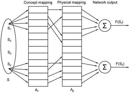
CMAC network is a kind of neural network that realizes associative memory through multiple mappings. It simulates the function of the cerebellar cortical nervous system to sense and store information and use information by association. CMAC not only has a fast-learning speed, but also has a high accuracy, which has an important application value in the field of intelligent control [12]. The network structure of CMAC is shown in the Fig. 5.
3.2. CMAC-PID parallel control system
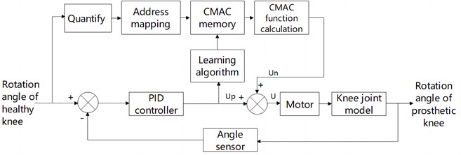
CMAC and PID parallel control algorithm is adopted in this paper, and the controller structure is shown in the Fig. 6. The output of CMAC network is , and the output of PID controller is . In the initial stage, the controlled object receives the control signal jointly output by CMAC and PID. The purpose of this control system is that, after continuous learning, the difference between the total control input and the output of CMAC will be smaller and smaller, and finally the control signal of the controlled object will be completely generated by CMAC, so that the system can respond more quickly and have higher accuracy.
Fig. 5CMAC network architecture
Beforehand, some researchers have found the advantages of CMAC-PID control. In 2009, Wen Xia and others proposed CMAC and PID compound control strategy of DC motor [13]. Compared with conventional PID algorithm, the controller improves the non-linear approximation ability of the system; In 2018, Pei Jianjun and Wang Hongwen found that adopting the CMAC-PID control plane manipulator hydraulic drive system can improve the motion trajectory response speed and tracking accuracy of the manipulator than conventional PID control [14]. Next, CMAC-PID control will be applied to the prosthetic knee system and compared with traditional control algorithm to verify its advantages. The nomenclature of symbols CMAC-PID control system is listed in Table 2.
Table 2Symbol nomenclature of CMAC-PID control system
Symbol | Meaning |
Neural network parameter | |
Network learning rate | |
Inertia | |
Generalization parameter | |
Output signal of CMAC network | |
Output signal of PID controller | |
Total output signal of the control system |
The calculation formula of the control system is:
where, is the binary selection vector, is the generalization parameter, is the output signal of CMAC network, is the output signal of PID controller, and is the total output signal of the control system, namely the input signal of the controlled object. The adjustment index of CMAC is [15]:
where is the network learning rate, , is the inertia, [2].
Fig. 6Control system of the prosthetic knee
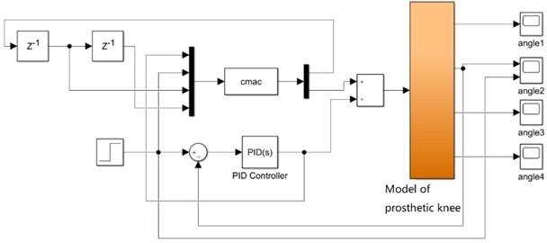
Import the established prosthetic knee joint model into MATLAB, as shown in Fig. 7, and then input step signal and constant signal to the system respectively [13]. Here, the angle of one bar in the four-bar mechanism is selected as the research object to provide feedback information for the controller to learn and adjust itself. After calculation of relevant formulas, the change of knee joint rotation angle can be obtained according to the angle change of the bar.
Fig. 7Simulation model of the prosthetic knee
4. Simulation results and analysis
After the step signal and the constant signal are input into the control system, the simulation performance is compared between the single PID control and the CMAC-PID composite control, where, the parameters in CMAC network are set as follows: 100, 5, 0.1, 0.04, in PID control: 3, 15, 1.5. These parameters are applied in Fig. 8 to Fig. 11. The simulation results are shown below.
Fig. 8Input step signal: single PID control
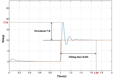
Fig. 9Input step signal: CMAC and PID compound control
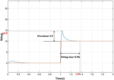
It can be seen from the simulation results in Fig. 8 and Fig. 9 that when the input signal is a step signal, the output signals of both systems approach the input signal in a short time. However, when the input signal changes instantaneously, the overshoot of the system under PID control (Fig. 8) is about 7.8, and the time required to fully fit with the ideal output signal is about 0.69 s. In the CMAC and PID compound control system (Fig. 9), the overshoot is about 4.9, and the fitting time is about 0.39s. Compared with single PID control, the overshoot of the prosthetic knee system under CMAC and PID composite control is reduced by 37.2 % and the fitting time is reduced to 56.5 %. Therefore, the compound control algorithm has smaller overshoot and faster response.
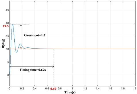
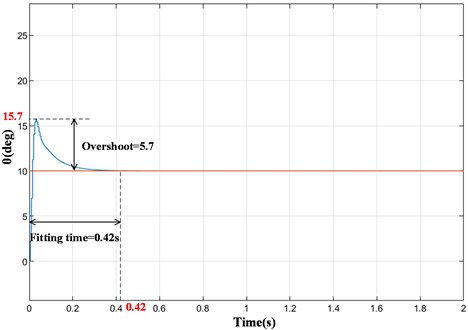
As can be seen from Fig. 10, when the input signal is a constant signal, the overshoot is about 9.5 and the fitting time is about 0.69 s under PID control. After the CMAC algorithm is added (Fig. 11), the overshoot is significantly reduced to 5.7, and the fitting time is also shortened to 0.42 s. Therefore, when the input signal is a constant signal, the overshoot of the prosthetic knee system under CMAC and PID composite control is reduced by 40 % and the fitting time is reduced to 60.9 %. It can be seen that the CMAC and PID compound control system has shorter response time and higher precision than the traditional PID control system. It's worth noting that after finding the optimal value, the output signal may still fluctuate slightly, and the system is still in the process of constant adjustment.
Fig. 10Input constant signal: single PID control
In the prosthetic knee joint control system, compared with traditional PID control, the addition of CMAC reduces the overshoot by 37.2 % to 40 % and fitting time by at least 43.5 %, thus the system has better real-time performance, which is beneficial to the control of prosthetic knee. Due to CMAC is a local approximation network, and there are fewer weights to adjust, it has the characteristics of small output error, good real-time performance and strong robustness.
Fig. 11Input constant signal: CMAC and PID compound control
5. Conclusions
This paper aims to design a prosthesis knee that can provide the active torque for the knee joint. Firstly, the structural parameters of prosthesis knee joint are determined according to the ICR of healthy knee joint. Then, mechanical design is carried out with mechanism parameters. Finally, a control system for prosthetic knee joint was established-CMAC and PID compound control, which improves the response speed and tracking accuracy of the prosthetic knee.
In this paper, a new active prosthesis knee joint structure has been designed, which can provide active torque for knee joint movement. The mechanical structure is optimized according to the motion law of the human knee joint so it has good bionic performance. In addition, a control system-CMAC-PID control system for the knee joint has been established. It is proved that the response effect of the CMAC-PID control system is better than that of the traditional control system on the prosthetic knee joint.
References
-
R. K. Mohanty, R. C. Mohanty, and S. K. Sabut, “A systematic review on design technology and application of polycentric prosthetic knee in amputee rehabilitation,” Physical and Engineering Sciences in Medicine, Vol. 43, No. 3, pp. 781–798, Sep. 2020, https://doi.org/10.1007/s13246-020-00882-3
-
J. Liu, Advanced PID control MATLAB simulation. (2nd edition), (in Chinese), Publishing House of Electronics Industry, 2004.
-
J. Zhang and Y. Wu, “Research on application of CMAC and PID parallel control method in airborne satellite antenna servo system,” (in Chinese), in Proceedings of 2016 IEEE Chinese Guidance, Navigation and Control Conference, pp. 3105–3109, 2016.
-
C. W. Radclife, “Biomechanics of knee stability control with four-bar prosthetic knees,” (in Australian), in Proceedings of the ISPO Australia Annual Meeting, 2003.
-
M. G. Bernal-Torres, H. I. Medellín-Castillo, and J. C. Arellano-González, “Design and control of a new biomimetic transfemoral knee prosthesis using an echo-control scheme,” Journal of Healthcare Engineering, Vol. 2018, pp. 1–16, 2018, https://doi.org/10.1155/2018/8783642
-
X. Wu, S. Zhai, and Q. Hao, “Optimization and simulation of four bar mechanism of prosthetic knee,” (in Chinese), Mechanical Design, Vol. 28, No. 9, pp. 42–45, 2011, https://doi.org/10.13841/j.cnki.jxsj.2011.09.010
-
Y. Shuai et al., “Selection and optimization of multi-center knee mechanism,” (in Chinese), Journal of Jianghan Petroleum Institute, Vol. 23, No. 4, pp. 86–88, 2001, https://doi.org/10.3969/j.issn.1000-9752.2001.04.032
-
B. Wu, Z. Chen, and M. Cheng, “Design and simulation of novel prosthetic knee,” (in Chinese), Mechanical Design and Manufacturing, Vol. 53, No. 6, pp. 5–8, 2015, https://doi.org/10.19356/j.cnki.1001-3997.2015.06.002
-
L. Zhang, W. Lu, and X. Cao, “Optimization design of four linkage bionic knee mechanism,” (in Chinese), Machine Tool and Hydraulics, Vol. 43, No. 9, pp. 67–70, 2015, https://doi.org/10.3969/j.issn.1001-3881.2015.09.019
-
C. Yang, “Research on human motion trend perception based on lower limb joint torque calculation and prediction,” (in Chinese), Harbin Institute of Technology, 2015.
-
L. Han, Theory, Design and Application of Artificial Neural Network. (in Chinese), Chemical Industry Press, 2002.
-
X. Yue et al., “Application of CMA-PID in brushless DC motor control system,” (in Chinese), Instrument Technology and Sensor, Vol. 53, No. 7, pp. 112–114, 2016, https://doi.org/10.3969/j.issn.1002-1841.2016.07.030
-
X. Wen, L. Wu, Q. Li, and W. Ren, “Design of CMAC-PID intelligent control system for DC motor based on Matlab,” (in Chinese), Journal of Sanming University, Vol. 26, No. 2, pp. 165–167, 2009, https://doi.org/10.14098/j.cn35-1288/z.2009.02.019
-
J. Pei and H. Wang, “Research on hydraulic system modeling and CMAC-PID control for driving planar manipulator,” (in Chinese), Chinese Journal of Construction Machinery, Vol. 16, No. 3, pp. 225–230, 2018, https://doi.org/10.15999/j.cnki.311926.2018.03.008
-
H. Yu et al., “CMAC control and example simulation of intelligent prosthetic leg,” (in Chinese), Control Engineering, Vol. 17, No. 2, pp. 60–62, 2010, https://doi.org/10.14107/j.cnki.kzgc.2010.02.029
About this article

