Abstract
The biped dynamic walker considered in this paper has three actuators - two at the ankle joints and one at the hip joint. We consider the case of one of the two ankle actuators at fault. Despite having only two actuators operational, we show that successful gait is possible for a typical case of virtual passive dynamic walking. We analyze such gaits for local and global stability for a virtual slope and for the cases of completely unpowered or partially powered alternate steps. It is shown that completely unpowered alternate steps are preferred over partially powered alternate steps in the case of virtual passive dynamic walking for global stability, and the other way for local stability.
1. Introduction
Biped walking imitates human locomotion mechanism through alternate stance and swing phases of the robot’s legs. This kind of walking generally involves sophisticated and complex nonlinear hybrid dynamics with multiple variables. However, a class of bipeds called passive dynamic walkers can walk down a gentle slope powered by gravity alone. In order to simplify analysis and control input generation for biped robots, dynamic walking involving passive dynamics is considered. Research in passive dynamic waking was initiated by McGeer et al. [1], who gave the first mathematical model to analyze dynamic walking. Later Goswami et al. [2] introduced the widely used compass gait model for passive dynamic walkers and gave the concept of limit cycle walking in terms of symmetry and chaos. He also proposed the control law based on energy, which is used in the application of active walking on level grounds. Asano et al. [3] proposed the concept of active level walking of a compass gait model based on virtual gravity concept. He explained the active level walking of compass gait with and without knee. Spong et al. [4], has also studied and proposed the concept of passivity control and energy shaping [4]. Asano analyzed under actuated virtual passive dynamic walking with semi-circular feet. Apart from that, he also covered the stability, dynamics, and model analysis using unified properties of virtual passive dynamics models [5-8]. To the best our knowledge, dynamic walking with actuator fault has not be studied by researchers in this field. In this paper, we propose an active dynamic walker model based on the virtual gravity concept for the case of one ankle actuator fault. The fault is assumed to make the joint free with zero torque or resistance applied by the faulty actuator. This situation is modeled as one step of the gait cycle fully powered and another step, where the leg with the faulty ankle actuator is in stance phase, partially powered by the hip actuator alone.
2. Biped dynamic walker modeling
We have considered the Virtual Passive Dynamic Walker (VPDW) model and chosen the model parameters from Asano et al. [9]. The schematic diagram of the virtual passive dynamic walker is shown in Fig. 1. The system dynamics consists of two-phases – swing phase and stance phase with an impulsive transition in between. It has to be satisfied with the geometrical conditions given by Asano et al. [9] for the impulsive transition. The equation of motion is given by:
where 𝑀 – mass matrix, 𝐶 – Coriolis or centripetal matrix, 𝐺 – gravitation matrix.
The impulsive transition during impact for virtual passive dynamic walker can be referred to as [5], i.e.:
where . The mapping of position and velocity before and after the collision has been done by using these two matrices and .
Fig. 1Schematic of the biped dynamic walker robot
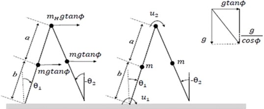
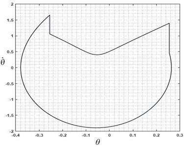
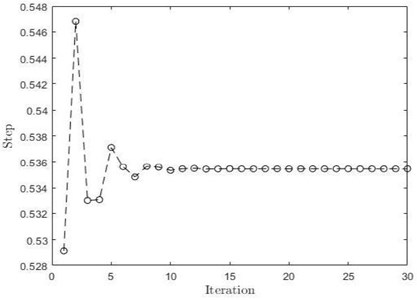
Fig. 2a) Limit cycle plot of VPDW, b) step length convergence plot of VPDW
a)
b)
From suitably chosen initial condition and slope value, the dynamic walker walks on flat surface robustly. We observe this from a numerical simulation which shows convergence for the given initial condition. As shown in Fig. 2(a), the system starts with some initial condition and approaches a fixed step length after 10th iteration, Fig. 2(b) shows limit cycle converging to the stable solution from its initial condition. The above two figures show the mathematical assurance of the robustness of the VPDW [9].
3. Problem description
In active biped dynamic walking, we realize the case where one of the actuators undergoes a fault condition. Generally, in typical flat surface dynamic walking, all motors will be in active phase. Some faulty situations may arise on the hip joint or on one of the ankle joints in some adverse conditions. In this paper, we consider one of the ankle actuators to be non-functional due to fault. As discussed in the earlier section, dynamic walking is a nonlinear dynamical phenomenon where each link's dynamics is coupled with another one. We have chosen the virtual passive dynamic walker as a reference model for control input generation. Each gait cycle consists of two steps. The fault condition is analyzed in two cases: (a) alternate steps consist of powered (ankle and hip) and unpowered (none), and (b) alternate steps consist of powered (ankle and hip) and partially powered steps (only hip). We did numerical analysis of the above-mentioned cases in terms of global and local stability based on Poincare map and basin of attraction plot.
3.1. Alternate powered and unpowered steps dynamic walker
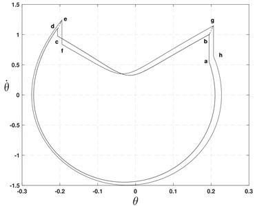
An Alternate Powered and Unpowered Step Dynamic Walker (APUSDW) is a special case of VPDW in which the first step is considered as powered, and the next one is unpowered. So whatever energy is pumped into the system during the powered cycle is not going to be lost completely during the impulsive transition. The dynamic walker is able to walk without any energy input during the unpowered cycle by using residual energy. The governing equations of motion is a combination of the passive and active dynamic models on the flat surface. These are given by Eq. (1) along with the transition condition Eq. (2) for powered step. The equation of motion for the unpowered step is similar to the powered step, but on the right-hand side of Eq. (1) would be 0. One practical significance of the alternate powered walker is that while walking both motors stop supplying the power. However, the walker can still manage robust walking. Fig. 4 indicates that the system gets converged at two limit cycles for the powered and unpowered case.
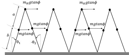
Fig. 3Schematic of alternate powered and unpowered steps dynamic walker
3.2. Alternate powered and partially powered steps dynamic walker
In this section, we consider the Alternate Powered and Partially Powered Steps Dynamic Walker (APPPSDW). The second step always behaves like an underactuated system with hip actuation alone active. The system dynamics is similar to APUSDW – equation of motion given by Eq. (1) along with the transition condition by Eq. (2). The equation of motion for the partially powered step is similar to the powered step but on the right-hand side of Eq. (1) will have . The result is similar to that shown in Fig. 4. There is convergence of limit cycle and step length. But the robustness of walking for this model is found to be less as compared to the other model.
4. Model analysis and numerical validation
Our primary focus is to develop a robust walking model for the case of ankle actuator fault based on the virtual passive dynamic walking concept. We modelled APUSDW and APPPSDW to find out the better of the two. We have also performed numerical and graphical analysis for these proposed models which show similar behaviour to VPDW. To ensure stability, we need to perform Poincare analysis and analyze how it behaves over the variation in slope parameter 𝜙.
Fig. 4Limit cycle plot of APUSDW
4.1. Stability analysis
Many researchers use Lyapunov concept to find the stability of the nonlinear systems. However, the conventional definition of stability in the Lyapunov sense (about the fixed point) is not suitable for these nonlinear system models due to their hybrid nature, since the periodic solutions cannot be asymptotically stable in the Lyapunov sense. Therefore, we need to define the stability of the system in a periodic or orbital sense. A periodic orbit’s stability for an autonomous system can be calculated by considering Poincare map, which replaces the n-dimensional continuous vector field’s flow with an n-1 dimensional map [10]. The impact point of a dynamic walker is a natural choice for Poincare section, and its successive transition can be related by where, represents the state vector of the robot. If the is a fixed point for mapping, we can also write . For small perturbation , using Taylor series expansion, we can elaborate . By referring to Guckenheimer et al. [10], we could conclude the stability by calculating the max singular value of ∇𝑃 and by plotting the eigenvalues of ∇𝑃. As shown in Fig. 5(a) and Fig. 5(b), the eigenvalues of APUSDW and APPPSDW are inside the unit circle [1, 11]. We can conclude that our model shows limit cycle stability. The maximum eigenvalue of alternate powered and unpowered is greater than the alternate powered and partially step model. So we can say that the alternate powered and unpowered step model is less stable locally in the neighbourhood of its fixed point.
Fig. 5Eigenvalues plot for APUSDW and APPPSDW
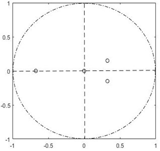
a) APUSDW
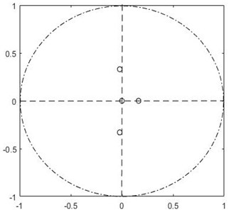
b) APPPSDW
4.2. Basin of attraction
A set of points in state space for which the system can converge to a particular fixed point is known as the basin of attraction. For nonlinear dynamical systems, multiple solutions can exist which could be termed as stable if they fall in the region of basin of attraction. A stable attractor is a point, region, limit cycle, or orbit in state space where all trajectories tend. To better understand the system's global stability, we analyze a set of points around the fixed point. If the system is converging to the particular fixed points within that set, then we could say that the initial condition is stable. For our models, we have analyzed all possible combinations of and between 0.04-2° over the range of (included angle between legs at transition) from 0.01-0.5° for a given value of angular slope 1°. Among these initial conditions, some of them lie inside the basin of attraction, and some of them are not. Initial conditions outside of basin of attraction do not converge to any fixed points.
The basins of attraction for APUSDW and APPPSDW are respectively given in Fig. 6(a) and Fig. 6(b). It can be observed that Fig. 6(a) has a larger basin of attraction than that of Fig. 6(b).
Fig. 6Basin of attraction APUSDW and APPPSDW
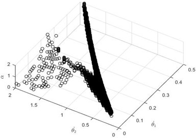
a) APUSDW
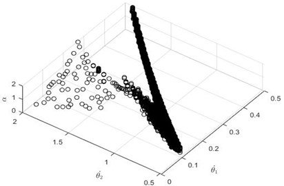
b) APPPSDW
Therefore, the global stability of APUSDW is better as it covers larger region of initial conditions leading to convergence. As far as local stability is concerned, APPPSDW performs better. However, it should be noted that this conclusion is limited in scope to control inputs generated from virtual passive dynamic walking which does not have knowledge of actuator fault. A controller which considers actuator fault could make APPPDW also better in terms of global stability.
5. Conclusions
We considered the case of biped dynamic walking in the presence of one ankle actuator fault. It was shown that biped walking in the presence of one ankle actuator fault can still lead to successful walking gait cycle. Two cases were analyzed: APUSDW and APPPSDW. Both were found to give stable walking although the controlled had no knowledge of actuator fault. However, for virtual passive dynamic walking base control algorithm considered, the APUSDW is shown to have better global stability. We wish to further investigate stability properties with other controllers which consider actuator fault in generating control inputs to the walker.
References
-
Goswami A., Thuliot B., Espiau B. A study of the passive gait of a compass-like biped robot: Symmetry and chaos. The International Journal of Robotics Research, Vol. 17, 1998, p. 1282-1301.
-
McGeer T. Passive dynamic walking. The International Journal of Robotics Research, Vol. 9, Issue 2, 1990, p. 62-82.
-
Asano F., Hashimoto M., Kamamichi N., Yamakita M. Extended virtual passive dynamic walking and virtual passivity-mimicking control laws. Proceedings ICRA, IEEE International Conference on Robotics and Automation (Cat. No.01CH37164), 2001.
-
Spong M. W., Bhatia G. Further results on control of the compass gait biped. Proceedings of the International Conference on Intelligent Robots and Systems, Vol. 2, 2003, p. 1933-1938.
-
Asano Fumihiko Limit Cycle Gaits. Humanoid Robotics: A Reference, 2019, p. 949-978.
-
Asano Fumihiko, Luo Zhi-Wei On energy-efficient and high-speed dynamic biped locomotion with semi-circular feet. IEEE/RSJ International Conference on Intelligent Robots and Systems, 2006, p. 5901-5906.
-
Asano Fumihiko, Luo Zhi-Wei, Yamakita Masaki Biped gait generation and control based on a unified property of passive dynamic walking. IEEE Transactions on Robotics, Vol. 21, Issue 4, 2005, p. 754-762.
-
Garcia Mariano, Chatterjee Anindya, Ruina Andy, Coleman Michael The simplest walking model: stability, complexity, and scaling. Journal of Biomechanical Engineering, Vol. 120, 1998, p. 281-288.
-
Asano Fumihiko, Yamakita Masaki, Kamamichi Norihiro, Luo Zhi-Wei A novel gait generation for biped walking robots based on mechanical energy constraint. IEEE Transactions on Robotics and Automation, Vol. 20, Issue 3, 2004, p. 565-573.
-
Guckenheimer J., Holmes P. Nonlinear Oscillations, Dynamical Systems, and Bifurcations of Vector Fields. Springer Science and Business Media, Vol. 42, 2013.
-
Ott Edward Chaos in Dynamical Systems. Cambridge University Press, 2002.
About this article

