Abstract
Lapping is one of the finishing technological operations. It can be performed using various manual and automated techniques. One of the most efficient lapping techniques is carried out with the help of vibratory equipment. Among a great variety of vibratory lapping, polishing and grinding machines, the ones of the overhead (suspended) type with double-mass oscillatory systems are not thoroughly investigated. Therefore, the novelty of the present study consists in development and investigation of the double-mass vibratory machine for single-sided lapping of flat surfaces. It consists of the upper lap and the lower carrier connected to one another by six springs radially directed and uniformly distributed along the circle of the lap. The parts, whose upper end faces are to be treated, are fixed in the lower carrier. The lapping process is performed due to the oscillatory motion of the lap relative to the carrier. The differential equations describing the motion of the machine’s oscillatory system are derived. The analytical dependencies for calculating the stiffness coefficients of the springs ensuring the energy-efficient resonance operation mode are deduced. Based on the results of experimental studies of friction forces exerted by each moving surface on the other one during the lapping process, the numerical modelling and computer simulation of the lapping machine operation are carried out. The obtained results can be used while investigating the technological parameters (surface roughness, flatness, accuracy etc.) of the lapping process carried out with the help of vibratory equipment.
Highlights
- The general design, the simplified calculation diagram, and the experimental prototype of vibratory machine for single-sided lapping of flat surfaces are proposed.
- The differential equations of motion of the machine’s oscillatory system are derived. The analytical dependencies for calculating the springs stiffness ensuring the energy-efficient resonance operation mode are deduced.
- Based on the results of experimental studies of friction forces during the lapping process, the numerical modelling and computer simulation of the lapping machine operation are carried out.
1. Introduction
Finishing treatment of flat surfaces of machine parts can be performed using various technological operations, in particular, grinding, polishing, lapping, burnishing etc. Depending on the operational requirements set for a part and the surfaces to be treated, these processes can be divided into two basic types – single-sided [1] and double-sided ones [2-5]. Considering the drives of technological machines for finishing treatment, most of them are equipped by electric motors and mechanical transmissions [1-5], while a relatively small number of such machines use vibration excitation for setting the working members into motion [6-10].
During the single-sided finishing treatment, only one surface of a part is machined. The results of investigations of lapping parameters and tool wear during single-sided treatment are presented in [1]. The publications [2-5] are dedicated to double-sided finishing treatment of flat surfaces, in particular, to investigating their technological parameters (roughness, flatness, accuracy etc.) [2, 3], to studying kinematic parameters and dynamic behavior of the working members (machining tools) [4], to analyzing friction processes between the surfaces of the parts being treated and the surfaces of the working members (machining tools) [5].
Despite numerous advantages of the electromechanically-driven finishing machines, their main drawbacks consist in design complexity due to application of several electrical drives that must be synchronized; reduced reliability caused by the use of several mechanical transmissions; relatively low degree of dimensional accuracy of the finished parts etc. The mentioned drawbacks can be partially avoided in the designs of finishing machines driven by electromagnetic vibration exciters [6-10]. In the work [6], the authors proposed the mathematical model of the bowl-type vibratory finishing machine, studied the dynamics of its excitation system, and analyzed the machine’s performance. The paper [7] considers the vibratory finishing process using loose abrasive media, and investigates the surface roughness behavior under different operational conditions. In [8], there has been modelled the kinematics of the treating media, and the material removal intensity during the finishing process.
Unlike numerous existing investigations, in [9, 10], as well as in the present paper, the authors made an attempt to propose the improved designs, to derive the mathematical models, and to study the dynamic behavior of vibratory finishing machines with circular oscillations of laps. The novelty of the present paper consists in development and investigation of the double-mass vibratory machine of the overhead (suspended) type for single-sided lapping of flat surfaces.
2. Design peculiarities and mathematical model of vibratory lapping machine
2.1. Design diagram and oscillatory system of vibratory lapping machine
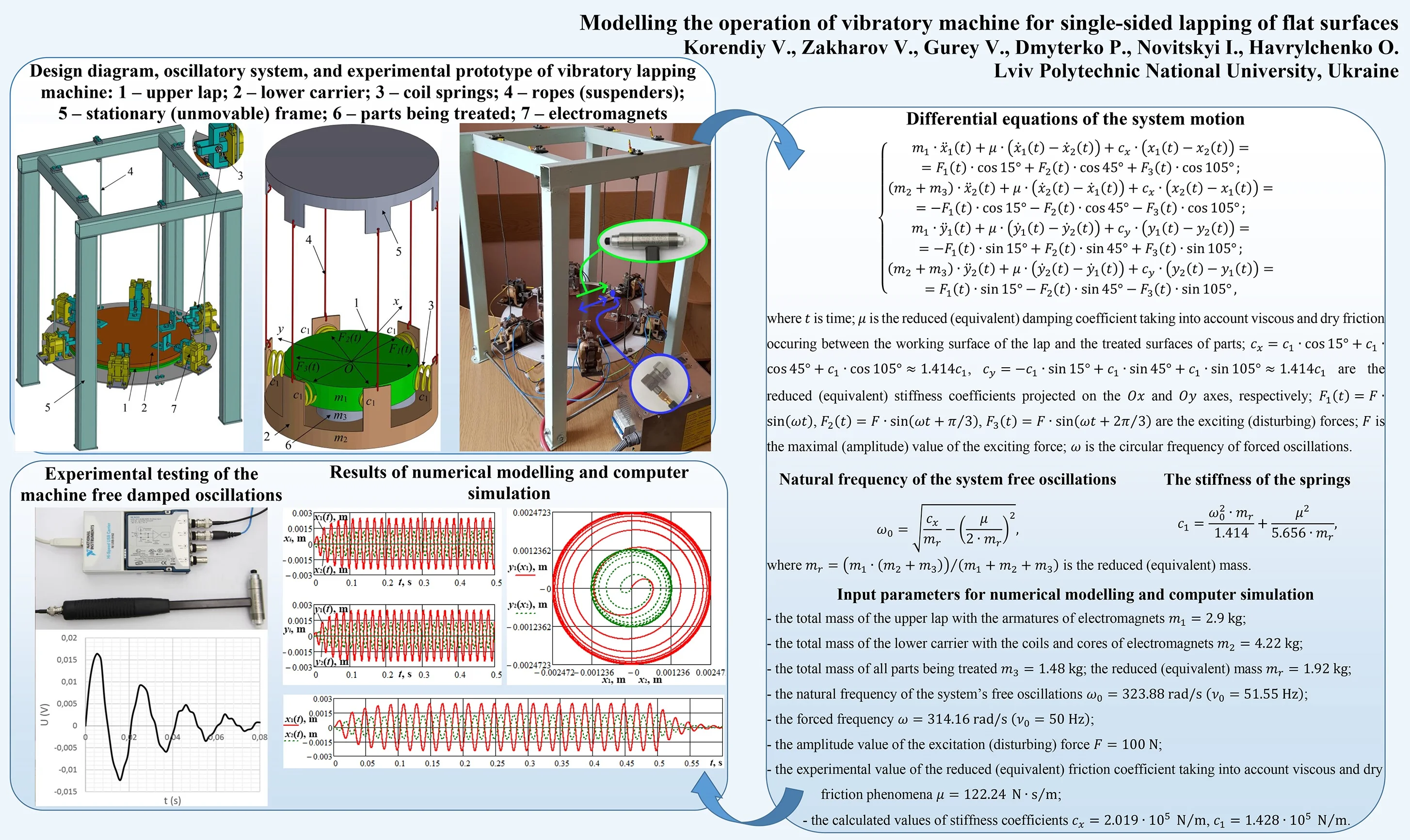
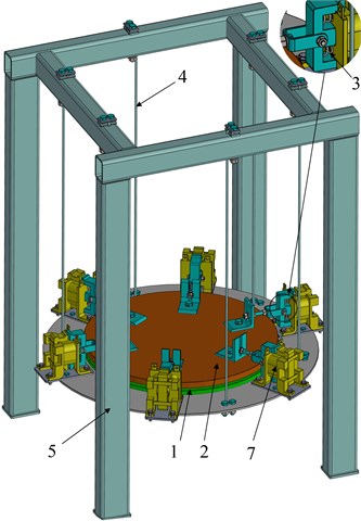
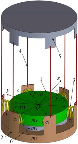
The proposed design of vibratory machine for single-sided lapping of flat surfaces is presented in Fig. 1(a), and its double-mass oscillatory system is shown in Fig. 1(b). The mass (upper lap 1) and the mass (lower carrier 2) are connected by six pairs of springs 3 of equal stiffness . The lower carrier 2 is suspended by six ropes 4 from the stationary (unmovable) frame 5.
Fig. 1Design diagram and oscillatory system of vibratory lapping machine: 1 – upper lap; 2 – lower carrier; 3 – coil springs; 4 – ropes (suspenders); 5 – stationary (unmovable) frame; 6 – parts being treated; 7 – electromagnets
a)
b)
The parts 6, whose upper end faces are to be treated, are fixed on the lower carrier 2 (Fig. 1). The total mass of all parts is equal to . Between the working face of the upper lap 1 and the upper faces of the parts 6 being treated, there is spread the lapping compound. The influence of the lapping compound on the system’s motion can be described by the corresponding viscous friction (damping) coefficient and dry friction coefficient . The vibration excitation provided by three pairs of electromagnets 7 can be modelled as the system of periodic forces , whose lines of action are level with the central axes of the corresponding coil springs 3. The excitation forces are applied between the upper lap 1 and the lower carrier 2.
2.2. Differential equations of the system motion and stiffness parameters of the springs
In general case, the considered oscillatory system (Fig. 2) is characterized by four generalized coordinates describing plane (two-dimensional) motion of the laps. Let , , , denote the displacements of the upper mass and the lower mass relative to the corresponding axes of the Cartesian coordinate system, whose origin is placed at the mass center of the upper lap in its equilibrium position (in its state of rest). The differential equations of the system’s motion can be written as follows:
where is time; is the reduced (equivalent) damping coefficient taking into account viscous and dry friction occuring between the working surface of the lap and the treated surfaces of parts; are the reduced (equivalent) stiffness coefficients projected on the and axes, respectively; , , are the exciting (disturbing) forces; is the maximal (amplitude) value of the exciting (disturbing) force; is the circular frequency of forced oscillations.
In order to ensure the efficient operation of the lapping machine under near-resonance conditions, it is necessary to define the corresponding stiffness parameters of its oscillatory system. Taking into account the fact that the upper lap and the lower carrier perform circular oscillations, which are characterized by equal projections of their maximal displacements on the and axes, let us analyze free oscillations of the corresponding double-mass vibratory system along the axis. In this case, let us consider first two equations of the system Eq. (1) and set 0 N. Assuming that the masses and oscillate with the same circular frequency but with different amplitudes decreasing in time, let us take the solutions of Eq. (1) with zero right-hand side as , , where , are the constants denoting the maximal amplitudes of and ; is the exponent characterizing the damping process. Substituting the proposed solutions into Eq. (1) with zero right-hand side, let us derive the characteristic equation and define the natural frequency of the system’s oscillations:
where is the reduced (equivalent) mass.
Considering the derived analytical expression Eq. (2) for calculating the natural frequency of the system’s free oscillations, it is possible to determine the necessary stiffness of the springs ensuring the energy-efficient resonance operation mode:
3. Results of experimental investigations and numerical modelling
3.1. Description of experimental technique and determination of damping coefficient
The experimental prototype of the vibratory machine for single-sided lapping of flat surfaces is presented in Fig. 2. The technique of carrying out experimental investigations consists in testing the system’s free damped oscillations using the measuring tools manufactured by PCB enterprise: the accelerometer of the M353 model, and the impact hammer of the M355B15 model. The processing (digitalization) of the obtained experimental data is performed with the help of the analog-to-digital (A/D) converter (digitizer) of the 9142 model manufactured by National Instruments enterprise. The amplitude and the frequency of the system free damped oscillations excited by the impact hammer are measured by the accelerometer. The obtained analog signal is processed by the analog-to-digital converter, and the plot of the digitalized signal describing the system free damped oscillations in the voltage form is presented in Fig. 2.
Fig. 2Experimental prototype of vibratory lapping machine, measuring tools, and results of testing the system’s free damped oscillations
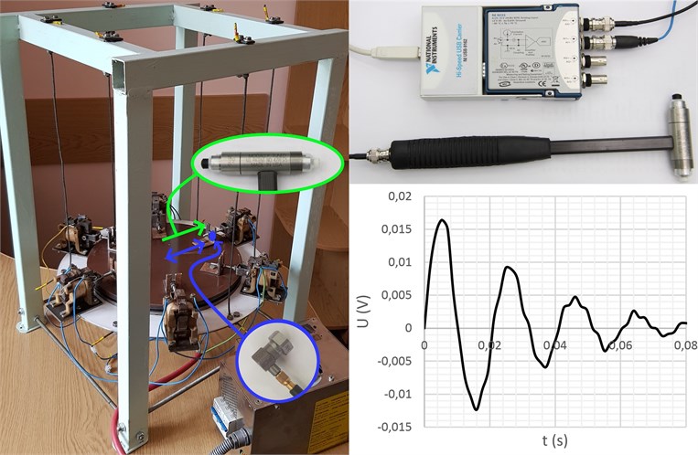
On the basis of the obtained experimental data (Fig. 2), the value of the reduced (equivalent) damping coefficient can be determined using the following formula:
where , are the amplitude values of two successive positive (or negative) peaks of the system free damped oscillations (taken on the basis of the converter’s digitalized signal in the voltage form); is the time period between the corresponding peaks.
In order to carry out further investigations on the machine’s operation, it is necessary to prescribe the corresponding inertia-stiffness parameters using the 3D solid model and the experimental prototype of the vibratory machine: the total mass of the upper lap with the armatures of electromagnets 2.9 kg; the total mass of the lower carrier with the coils and cores of electromagnets 4.22 kg; the total mass of all parts being treated 1.48 kg; the reduced (equivalent) mass 1.92 kg; the natural frequency of the system’s free oscillations 323.88 rad/s (51.55 Hz); the forced frequency 314.16 rad/s (50 Hz); the amplitude value of the excitation (disturbing) force 100 N; the experimental value of the reduced (equivalent) friction coefficient taking into account viscous and dry friction phenomena 122.24 (N∙s)/m (using Eq. (4) with 0.017 V, 0.009 V, 0.02 s, see Fig. 2). Substituting the input data into Eq. (3), we can calculate the values of the stiffness coefficients 2.019∙105 N/m, 1.428∙105 N/m.
3.2. Numerical modelling of the system motion
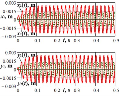
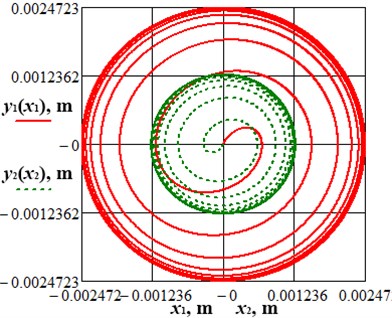
Using Eq. (1) and the above-given input data, let us simulate forced oscillations of the lapping machine’s vibratory system. Applying the Runge-Kutta method for numerical solving of the system of differential equations Eq. (1) in MathCad software, let us analyze the case of zero initial conditions: ; ; ; . The plots of the forced-vibration response of the upper lap and the lower carrier (time dependences of their displacements from the corresponding equilibrium positions), as well as the trajectories (paths) of the lap and the carrier during the machine starting (the time period 0…0.5 s) are presented in Fig. 3. The machine runs into steady-state operation mode in 0.2 s after the starting. The maximal displacement of the upper lap from its equilibrium position, i.e., the amplitude of its vibrations, is equal to 5.15 mm, and the system’s oscillations are characterized by circular trajectory (path).
Fig. 3Results of numerical modelling of the lap and the carrier motion during the machine starting
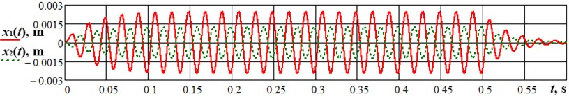
In order to verify the correctness of the derived mathematical model describing the motion of the lapping machine’s oscillatory system, let us simulate the shutdown condition (stopping process), and compare the obtained results with the ones of experimental investigations. In this case, let us assume that the amplitude of the excitation (disturbing) force takes zero value at the moment of time 0.5 s considering the machine starting conditions modelled above. The obtained results are presented in Fig. 4. Comparing the graphical dependence of Fig. 4 with the experimental plot given in Fig. 2, the conclusion about satisfactory agreement of the results of numerical modelling and experimental investigations can be drawn.
Fig. 4Results of numerical modelling of the machine shutdown condition (stopping process)
4. Conclusions
Based on the carried out investigations, the following conclusions can be drawn:
1) The possibilities of implementing vibratory equipment for performing various finishing technological operations (e.g., grinding, polishing, lapping, burnishing etc.) are of significant interest among technologists and researchers of technological processes and machines.
2) The general design of the electromagnetically-driven vibratory lapping machine and the simplified diagram of its double-mass oscillatory system has been considered; the differential equations describing the system motion have been derived; the analytical expression for calculating the stiffness parameters of the system have been deduced.
3) Prescribing the input parameters obtained on the basis of solid modelling and experimental testing of the vibratory lapping machine, the numerical modelling of the system motion has been carried out; the results of theoretical investigations (modelling) have been compared with the results of experiments, and the conclusion about their satisfactory agreement has been drawn.
References
-
Piotrowski N. Tool wear prediction in single-sided lapping process. Machines, Vol. 8, Issue 4, 2020, p. 59.
-
Klamecki B. E. Comparison of material removal rate models and experimental results for the double-sided polishing process. Journal of Materials Processing Technology, Vol. 109, Issue 3, 2001, p. 248-253.
-
Deaconescu T., Deaconescu A. Developing an analytical model and computing tool for optimizing lapping operations of flat objects made of alloyed steels. Materials, Vol. 13, Issue 6, 2020, p. 1343.
-
Hashimoto Y., Kondo R., Furumoto T., Hosokawa A. Development of highly accurate simulation model of wafer behavior considering contact between wafer and carrier during double-sided lapping. Journal of the Japan Society for Precision Engineering, Vol. 83, Issue 5, 2017, p. 433-438, (in Japanese).
-
Hashimoto Y., Sano T., Furumoto T., Hosokawa A. Development an identification method of friction coefficient between wafer and carrier in double-sided lapping. Precision Engineering, Vol. 56, 2019, p. 364-369.
-
Hashimoto F., Johnson S. P. Modeling of vibratory finishing machines. CIRP Annals, Vol. 64, Issue 1, 2015, p. 345-348.
-
Wan S., Liu Y. C., Woon K. S. A simple general process model for vibratory finishing. The International Journal of Advanced Manufacturing Technology, Vol. 86, 2016, p. 2393-2400.
-
Tian Y. B., Zhong Z. W., Tan S. J. Kinematic analysis and experimental investigation on vibratory finishing. The International Journal of Advanced Manufacturing Technology, Vol. 86, 2016, p. 3113-3121.
-
Kuzio I., Zakharov V., Korendiy V. Modelling the process of dressing the laps of vibratory finishing machine. Avtomatizacìâ Virobničih Procesìv U Mašinobuduvannì Ta Priladobuduvannì, Vol. 52, 2018, p. 32-42.
-
Zakharov V., Kuzio I., Korendiy V., Dmyterko P. Analysis and improvement of design diagrams and mathematical models of vibratory lapping machines. Ukrainian Journal of Mechanical Engineering and Materials Science, Vol. 5, Issues 3-4, 2019, p. 44-56.
Cited by
About this article

