Abstract
There is a large amount of information about the wear failure status in the particles, and the current wear failure status can be judged by monitoring them. In this paper, the main shaft bearing wear failure causes the change of metal particles in the lubricating oil and further causes the deterioration of the bearing condition. Based on the lubricating oil metal chip particle test system on the bearing testing machine, the particle size distribution change data in the bearing oil is obtained and the metal oil The main bearing fault prediction model with particle number and particle size as characteristic parameters realizes the fault diagnosis and condition evaluation of main shaft bearing wear based on the lubricating oil metal chip particle test, thereby effectively providing technical support for turboshaft engine fault diagnosis.
1. Introduction
In terms of oil wear fault diagnosis, Zhang Yong et al. [1] designed a real-time detection system for the pollution degree of on-board lubricating oil to detect the overall pollution degree of lubricating oil and the wear of equipment. Wang Lidong et al. [2] explained in detail the fault diagnosis of spectroscopy and ferrograph in diesel locomotives. Xiao Yunpeng et al. [3] applied the grey relational analysis theory to obtain the relationship between the particle content and the degree of oil pollution on the correlation degree of the spectrum and ferrograph data. Wang Zilu et al. [4] developed an oil online monitoring system with an ARM processor, which can stably and accurately monitor its pollution level. Feng Yaoguo et al. [5] designed a set of oil pollution particle detection counter based on LED technology, which can perform normal detection under low temperature conditions, and the test is stable and reliable. Kang Zhanxiang et al. [6] used the photoelectric principle to design a set of detection sensors for the pollution degree of the hydraulic system, and has the advantages of simple operation, convenient carrying, and high intelligence.
Oil online sensors have developed rapidly abroad, and many mature products have been put into practical use. At present, in some advanced aviation countries, such as the United States, Canada, etc., airborne online oil monitoring sensors have been researched and developed. For example, the MetalSCAN oil wear monitor developed by GasTOPS in Canada [7, 8] is the current application The most extensive online monitoring equipment for oil wear particles, and has been successfully applied to F119, JSF F135 engines and lift fans, Eurofirhter EJ200, PT6 turboprop aircraft engines, Neptune Helicopters, GE T58 turboshaft engine lubrication systems, etc.; it is also active in China Carry out relevant research on oil online sensors. Based on the principle of electromagnetic induction, Yan Hongzhi et al. [9] and Fan Hongbo et al. [10] developed a solenoid-type magnetic induction large-wear metal particle online monitoring sensor and a new electromagnetic wear particle sensor, and developed a corresponding online wear particle testing system; Lu Yibin[11] used XRF technology to study on-line oil monitoring, using solid and powder detection, and radioactive isotope as the radioactive source, which made it possible to apply it to the online monitoring of aero-engines. Ye et al. [12]found the factors affecting the change of hydraulic oil by analyzing its conductivity, and realized the online monitoring of oil by monitoring the change of its conductivity.
2. Test device and system
The bearing module, supporting module, etc., in order to ensure the stability, safe operation and accurate testing of the tester, the whole of the tester is placed on the cast iron foundation. The overall physical picture of the tester is shown in Fig. 1; the online lubricating oil particle detection sensor is installed before the spindle bearing, at the lowest point of the oil return pipeline, and the oil injection lubrication system is shown in Fig. 2.
Fig. 1Overall physical picture of bearing test
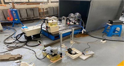
Fig. 2Oil injection lubrication system

3. Experimental conditions of bearing wear failure
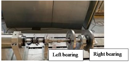
This experiment is an eccentric wear experiment carried out under the condition of unbalance and misalignment of the rotor system. As shown in Fig. 3, the experimental conditions are that the height adjustment of the left and right bearing seats is 0.75 mm, and the offset of the right bearing is 33.5 g. The right bearing is the test bearing.
Fig. 3Bearing test bench
Experiment process: Check whether the temperature sensor, vibration sensor, and oil sensor are in good contact, and then turn on the power. During the partial wear experiment, first let the rotor run at 3300 rpm for 20 minutes, stop for four minutes and wait for the speed to be zero, then Then run at 3900 rpm for 20 minutes. After three minutes of shutdown, wait for the speed to be zero, adjust the speed to 4500 rpm, and run for another 20 minutes. After three minutes of shutdown, wait for the speed to be zero. Finally, adjust the speed to 5100 rpm and run for 20 minutes.
Collect experimental data on the number of oil particles and draw them, as shown in Fig. 4.
To remove the data interference factors caused by bubbles in the oil circuit, it can be seen from the trend diagram of the number of small particles of Fe that in the whole bearing operation stage, the number of >4 μmFe particles has always maintained a certain increase, and the number of Fe particles in the other three sizes has shown a trend of first increase and then decrease. The increase in the number is mainly due to the running-in stage of the new bearing, and the decrease in the number is mainly due to the low speed operation to the medium speed stage, and the bearing has been seriously damaged. In the high speed operation stage, the damage rate of the bearing is not as large as before.
Fig. 4Trend chart of Fe quantity of bearing wear failure
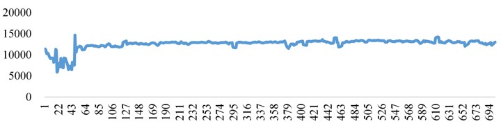
a) > 4 umFe
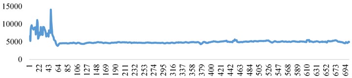
b) > 6 umFe
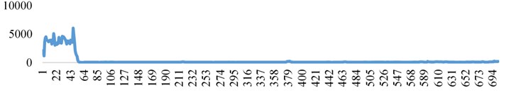
c) > 14 umFe
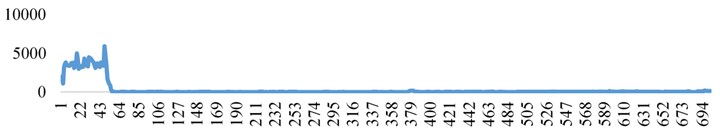
d) > 21 umFe
e) Fe quantity chart
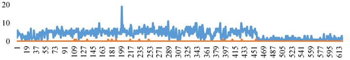
It can be seen from the trend diagram of the number of large particles of Fe that when the bearing runs below 4500 rpm, the amount of Fe in the range of 70-90 μm increases continuously with the increase of the rotational speed, and the growth rate is very large. At the same time, due to the serious wear of the inner surface of the rolling element and outer ring caused by the long-term operation of the bearing, during the operation of the bearing, 90-110 μmFe particles occasionally appear. After the bearing reaches the speed of 4500 rpm, with the continuous increase of the rotational speed, the bearing enters a relatively stable operation process, and the increase in the amount of large particles of Fe is significantly reduced.
In summary, when the bearing operates at medium and low speeds, the rotational speed has a great influence on the number of Fe particles in each stage of the bearing. When the bearing operates at high rotational speed, the number of small particles is only >4 μmFe and >6 μmFe, while the number of >14 μmFe and >21 μmFe is very small. At the same time, the influence of high rotational speed on the number of large particles with two sizes is not large at low rotational speed. However, with the increase of rotational speed, the wear degree will increase accordingly, and the number of large and small particles will increase.
4. Mapping relationship model between wear failure and lubricating oil metal shavings
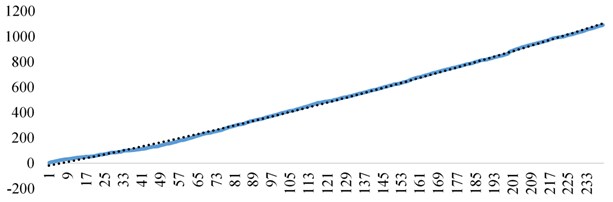
From the previous analysis, it can be seen that the number of lubricant metal chip particles under wear condition is constantly changing. The experiment starts from the normal stage, and accelerates the wear experiment of the bearing by adding rotor unbalance and misalignment. That is to say, the bearing can be divided into three stages from the healthy state to the later stage of wear: the early stage of wear, the middle stage of wear and the late stage of wear. Now the total number of particles at any time of the first gear lubricant metal chip (70 μmFe-90 μmFe) in the three stages is analyzed. Figs. 5, 6 show the scatter plot of the total number of lubricating oil metal debris particles changing with time at any time of early wear, and they are fitted by first-order and second-order polynomial.
Fig. 5First-order fitting of the total number of lubricating oil metal chips in the early wear state with time
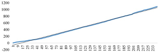
Fig. 6The second-order fitting of the total number of lubricating oil metal chips in the early wear state with time
The fitting functions of each order can be obtained as follows:
– The first-order fitting function is 4.694367063.
– The second-order fitting function is –0.00463.58222.77.
Judging from the fitting effect diagrams in Figs. 5 and 6, the second-order fitting is most in line with the changes in the number of particles.
Therefore, the relationship between the total number of lubricating oil metal chips in the early wear state and time can be described by a quadratic function of one variable as follows:
By analyzing the scatter plot of the total number of lubricating oil metal scrap particles worn in the middle and late stages with time, and fitting it with a first-order polynomial, the fitting curves of Figs. 7 and 8 are obtained.
Fig. 7First-order fitting of the total number of lubricating oil metal scrap particles in the mid-term wear state with time
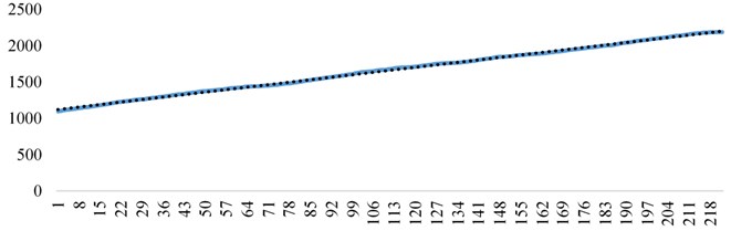
Fig. 8First-order fitting curve of the total number of lubricating oil metal chips in the late wear state with time
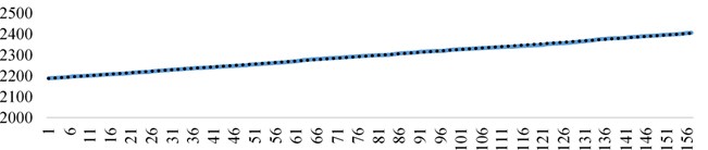
The first-order fitting curve of the total number of lubricating metal debris particles changing with time in the medium wear state is 4.8815 1117.9, and the first-order fitting curve of the total number of lubricating metal debris particles changing with time in the late wear state is 1.39 2186.1, which can be described by the following linear functions:
Fig. 9Scatter diagram of the total number of metal chips (90 μmFe-110 μmFe) in the second gear oil over time
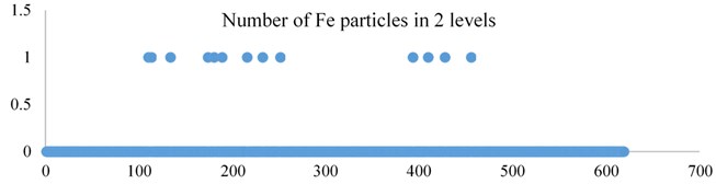
It can also be seen from Fig. 9 that 90 μmFe-110μmFe occasionally has one particle in the early and middle stages.
Therefore, for wear faults, the total number of particles with the smallest diameter can be used to express the wear status. From the previous fitting results, it can be seen that in the middle of wear, the total number of particles with the smallest diameter shows the largest increase over time, indicating that the degree of wear of the bearing is the largest in the middle of wear, and in the late wear. At that time, the total number of particles with the smallest diameter showed the smallest increasing trend over time, indicating that the degree of wear of the bearing is the smallest in the late stage of wear. Based on the above analysis results, it can be concluded that the mapping relationship model between the smallest particles of lubricating oil metal chips and the wear condition failure is:
where and are the total number of small-size particles of lubricating oil metal shavings, and are the coefficients of variation of the number of metal shavings particles, is time, and and are constants, which represent small-size metal shavings under steady-state wear. Average number of particles.
5. Conclusions
This article summarizes the experimental process of turboshaft engine wear failure, the experimental device and the experimental process of lubricating oil metal chip detection, records and briefly analyzes the change law of lubricating oil metal chip with time in the case of main bearing wear failure during the experiment, and analyzes The reason for the data and the influencing factors of the data change. In-depth analysis of the particle size and quantity of lubricating oil metal debris on the characterization ability of the main bearing wear failure, and the establishment of a mapping relationship model between wear failure and lubricating oil metal debris to determine the fault state of the bearing wear failure, through The analysis shows that as the speed increases, the degree of bearing wear failure will deepen at any time, but after reaching a certain speed, the wear effect does not deepen as the speed increases.
References
-
Zhang Yong, Huang Jianpeng, Zhang Wei Design of real-time detection system for pollution degree of vehicle-mounted lubricants. China Testing and Testing, Vol. 41, Issue 4, 2015, p. 61-65.
-
Wang Lidong, Shi Chengjiang The principle of spectroscopy and ferrograph and its application in equipment diagnosis. Harbin Bearing, Vol. 29, Issue 3, 2008, p. 52-55.
-
Xiao Yunpeng, Zhao Yuanli, Wu Xiaowen, et al. Correlation analysis between the pollution degree of aero-engine in-use lubricating oil and the content of iron metal wear particles. Guangdong Chemical Industry, Vol. 41, Issue 13, 2014, p. 39-40.
-
Wang Zilu, Wang Chengbiao, Liu Xingju Design of an ARM-based online monitoring system for lubricating oil pollution. Manufacturing Automation, Vol. 1, 2014, p. 20-22.
-
Feng Yaoguo, Liu Defeng, Zhang Meiju, et al. Oil pollution particle detection counter based on LED technology. Measurement and Control Technology, Vol. 33, Issue 5, 2014, p. 14-16.
-
Kang Zhanxiang, Wang Yanshan, Hu Fei, et al. Research on pollution detection sensor of hydraulic system based on photoelectric principle. Measurement and Control Technology, Vol. 32, Issue 12, 2013, p. 1-3.
-
Muir D. M., Howe B. In-line oil debris monitor (ODM) for the advanced tactical fighter engine. SAE Paper No. 961308, 1996.
-
Hughes I., Muir D. On-line oil debris monitor for aircraft for engines. Practicing Oil Analysis Magazine, Vol. 11, Issue 2, 2000, p. 28-34.
-
Chen Zhixiong, Zuo Hongfu, Zhan Zhijuan, et al. Research on on-line wear particle electrostatic monitoring technology for full flow in lubricating oil system. Acta Aeronautica Sinica, Vol. 33, Issue 3, 2012, p. 446-452.
-
Chen Zhixiong, Zuo Hongfu, Zhan Zhijuan, et al. On-line wear particle electrostatic monitoring method for full flow of bearing steel friction pairs. Journal of Aeronautics and Dynamics, Vol. 27, Issue 5, 2012, p. 1096-1104.
-
Zhou Yu, Jing Bo Design of aircraft wireless embedded real-time oil monitoring system based on Zigbee protocol. Computer Measurement and Control, Vol. 18, Issue 11, 2015, p. 2465-2468.
-
Ye Chuan, Li Jianhua A method for online monitoring of oil contamination in hydraulic systems. Machinery and electronics, Vol. 1, 2010, p. 50-52.
About this article

Financial support from National Natural Science Foundation of China (51575178), Special Research Project on the Key Fields of Intelligent Manufacturing and New Materials in General Universities of Guangdong Province “Research on Health Monitoring and Intelligent Diagnosis of Main Drive Bearings of Shield Machines” (2020ZDZX2033).
