Abstract
The strain comparison of a pressure vessel made of HSLA 15CDV6 in a cylindrical shell membrane region in a pressure test is discussed in this paper. Non-linear finite element analysis (FEA) of thin-walled cylindrical pressure vessels has been carried out using ANSYS. Hoop strain obtained from FEA is not compared well with the pressure test data at the membrane location of the cylindrical shell where the strain gauge is mounted. So to explain the reasons for the difference in strains at the membrane region, the profile of the cylindrical shell at strain gauge region has been measured. The 3D FEA of the cylindrical region with the measured profile is performed. It is found that with measured profile the FEA is giving the strain close to measured strain in the hoop direction. This leads to the increase in strain and stress as having been demonstrated through mathematical modeling in the deviated profiles variations of cylindrical shells. Therefore, the stresses in the deviated region are greater than those that would exist in an undeviated cylindrical shell, which reduces the margin of safety with respect to the yield strength of the material and causes stress concentration. The details of the stress analysis carried out including the effect of measured 3D profile variation are discussed in this paper.
Highlights
- The 3D FEA of the cylindrical region with the measured profile having waviness is performed.
- It is found that with measured profile the FEA is giving the strain close to measured strain in the hoop direction.
- The presence of profile variation leads to the increase in strain and stress as having been demonstrated through mathematical modeling in FEA.
- Profile variation in cylindrical shell causes stress concentration and reduces the margin of safety with respect to the yield strength of the material.
1. Introduction
The common shapes of pressure vessels have the form of spheres, cylinders, cones, ellipsoids, composites. Cylindrical pressure vessels are used in various technological fields such as power or chemical engineering [1], marine [2], nuclear technology [3], rocket motor case manufacturing, and production of many weapon systems [4] and pipelines carrying hazardous products [5], storage barrels, railway or car cisterns and in non-industrial applications.
A profile deviation such as waviness/dent in a pressure vessel or pipe is a region where the radius of curvature of the wall differs from the average radius of the pressure vessel or pipe. If this region is of the same dimensions as the radius of the vessel and the change in curvature is small, the profile may be classified as an out of roundness in the pressurized structure. When the region is small and the curvature changes sign, the profile is severe. This type of imperfections in pressurized structures (pipes or pressure vessels) up to = 24 percent [6], where d is the depth of the dent root and is the pipe diameter, there is only a negligible effect on the pressure to rupture the pipe. This is relevant to ductile pipes which fail by plastic yielding. Internally pressurized shells having profile variations i.e. waviness or dent types of imperfections have a stress concentration effect [7]. The level of the stress raiser is determined by the stress concentration factor (SCF), which is introduced for typical geometry and shape changes or discontinuities [8]. The profile deviation types imperfections are susceptible to thin cylindrical shell buckling under compressive loads [9]. In pipe flow [10] cause the degree of turbulence in the flow regime, head loss difference, and pressure drop for gas flow in a not round cross-section of diameter due to the presence of profile variation. Cylindrical shells under internal pressure, associated with profile deviations/waviness/dents type’s imperfections or defects can degrade in-service performance due to stress concentrations.
The profile type of deviation (waviness) in the purely cylindrical region may occur during manufacture (rolling and heat treatment of sheets), shipping, or in-service operation. There are so many types of defects in pressure vessel manufacturing such as profile variation, waviness, kink, dent, ovality or noncircularity, weld mismatch, weld porosity, grinding below parent material, and weld shrinkage, etc. All types of manufacturing errors have a different way to analyze and inspect. Here, there will not be a unique way to generalize these problems. So one can attempt this type of deviation through finite element modeling to salvage the hardware for operational purposes. If we reject the hardware without checking its acceptability, it will become a compromise between the cost and time spent on designing.
Advances were made to the material used in their fabrication such as HSLA 15CDV6 steel in pressure vessel design having a nominal composition of 0.15C-1.25Cr-1Mo-0.25V [11], [12]. HSLA 15CDV6 steel is one of the high-strength materials being commonly used for the fabrication of various pressurized structures like rocket motor cases, storage tanks, gas bottles, etc. The prediction of failure pressure that a pressure vessel with a cylindrical shell can withstand is an important aspect of the design of pressure vessels. The design adequacy and performance, of this HSLA steel, have been looked into through hydro-burst pressure testing of motor cases [11]. Yielding of material and failure occurs when some functional stress or strain is exceeded. In fact, the geometric mismatch is inevitable and it may result from manufacturing errors. Failures in pressure vessels are happened due to poor quality control fabrication, improper or insufficient fabrication procedures including welding, heat treatment, or forming methods. Elastic stress in pressure vessels having a mismatch in circumferential seam weld joint [13], longitudinal seam or long-seam (LS) joint [4], presence of weld sinkage [14], and estimation of mismatch to compare the test strain [15] have been studied.
This paper shows the effect of profile variation in the membrane region of the thin cylindrical shell which causes strain difference between numerical modeling of the cylindrical portion of pressure vessel and experimental tests with the application of strain-gauge measurements. To elucidate, the actual profile in the cylindrical region is measured. Including the measured 3D profile variation, a finite element model is generated using ANSYS FEA and non linear (NL) analysis has been performed. The stress/strain results are presented away from profile variation (cylindrical shell without waviness/kink) and near profile variation with waviness in the cylindrical shell. It has been found that with modeling actual profile the strain obtained from FEA compared well with test data. It is observed that the deviations of the pressure vessel profile may lead to a significant increase of the von Mises (effective) stresses. As the literature has been gone through, there is not adequate research on the profile mismatch on the cylindrical shell with FEA of the pressure vessel reported. Because of no existence of analytical solutions for such profile deviated structures, numerical FE modeling, and analysis is the common practice in designing. This makes this study an original one in the pressure vessel design/analysis and FEA-ANSYS field. The novelty of the paper lies in the demonstration of the 3D modeling of a complex profile of pressure vessel in FEM, estimation of strain from FEA, comparison of strain with test data, estimation of stress from measured strain through experimental stress analysis, assessing the impact (stress concentration factor) of the defect on its stress state, and find its adequacy comparing the effective stress at profile variation/strain gauge location with the strength of the material.
This problem is a process of modeling the exact geometry in finite elements with available measured geometrical data. So no regularities of generalized conclusions could establish the defect on its stress state due to the non-availability of enough data. So, in future research, with available data for another type of geometries with a similar type of defects, can be taken up and generalized. However, this paper will be informative for researchers/field engineers working in the pressure vessel design field, as an example study about the requirement of quality of fabrication and its effect on hardware for industrial operation purposes.
2. Stresses in a thin cylindrical shell
A pressure vessel is said to be thin walled when ( ≥ 10; is radius and t is thickness of shell). These vessels are referred to as membranes and the associated stresses resulting from the internal or external pressure are called membrane stresses. These membrane stresses are tension or compression stresses in nature. The distribution of normal stress on a plane perpendicular to the vessel surface is basically uniform throughout vessel thickness. The membrane/ wall is assumed to be offered no resistance to bending. If the wall offers resistance to bending, there will be bending stresses in addition to membrane stresses.
In complicated vessel shapes subjected to internal pressure, the simple membrane-stress concepts do not enough to give adequate information of the true stress state. The examples that cause varying stress distributions in the vessel are (i) types of heads closing the vessel, (ii) effects of supports, (iii) variations in thickness and cross-section, (iv) nozzles, (v) external attachments, and (vi) self-weight, wind, and seismic. The above examples cause deviations from a true membrane shape and develop bending in the vessel wall.
In pressure vessels subjected to internal /external pressure, stresses are built in the shell wall. This is in state of is triaxial stress field and the three main stresses are: (i) longitudinal / meridional stress, (ii) circumferential / Hoop stress, and (iii) radial stress. The normal stresses σ resulting from the contained pressure in a pressure vessel can be related to the pressure () by seeing a free body diagram (section A-A) as shown in Fig. 1. These stresses are called membrane stress [16]. The stress acting parallel to the axis of the cylinder and normal to its circumference is called longitudinal stress . The stress acting parallel to the circumference of cylinder is called hoop stress . The radial stress in direct stress, which is a result of the pressure acting directly on the wall. In thin-walled vessels, radial stress is very small compared to the hoop and meridional stress is generally ignored. Thus, it assumes in analysis a biaxial state of the stress field.
Fig. 1Stresses in cylindrical pressure vessel [17]
![Stresses in cylindrical pressure vessel [17]](https://static-01.extrica.com/articles/22163/22163-img1.jpg)
Hoop stress:
Meridional stress:
The distortion energy theory (von Mises’s theory) considers failure to have occurred when the distortion energy accumulated in the component under stress reaches the elastic limit as determined by the distortion energy in a uniaxial tension test. It states that yielding will take place when:
For the biaxial consideration, The von Mises’s stress (effective stress) can be written as:
3. Finite element analysis
3.1. Geometry of cylindrical shell and profile measurement
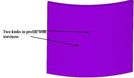
The geometry of the HSLA steel cylindrical configuration of the tank is 688 mm; 6 mm. The 3D profile is measured in both hoop and meridional directions in an area of 230 mm (in the circumferential direction)×250 mm (in the axial direction), around the strain gauge, where strain in the hoop direction was found a large difference in the cylindrical region as compared to membrane strain. Fig. 2 shows the measured profile variation foot print in a 230 mm×250 mm area. It is found from the measured profile that the strain gauge location in a cylindrical location having kink in profile with waviness.
Fig. 2Measured profile of cylindrical pressure vessel
3.2. Material: HSLA 15CDV6 steel
The material properties to be specified for the analysis are (i) Young’s modulus, 206010 MPa, (ii) Poisson’s ratio = 0.3, (iii) Stress-Strain curve (uniaxial) with = 834 MPa; = 981MPa.
The material property data for the analysis in software is from the stress strain curve of the material. Stress-strain curve is generated from tensile tests and represented through empirical relations. It is well known that a linear Hooke’s law cannot describe the behavior of most material under all strains. The inverse Ramberg-Osgood Eq. (5) of [19], [11] is used to represent the stress () – strain () curve of the material. This curve would assure us of the existence of some function of strain describing stress , which is necessary for predicting the behavior of materials and structures.
The inverse Ramberg-Osgood equation represented the stress () – strain () curve of the material as follows:
It can be obtained from Eq. (5):
where the strain at 0.2 % proof stress () level:
For the above specified material properties, the material constants in Eq. (1) are found to be: = 0.0047 and = 2.72).
In the above equation, the parameters as described in the paper utilizes the standard Young’s Modulus for and strength of material and calculates material constants and (parameter defining the shape of the nonlinear stress-strain relationship). The stress strain data generated from the relation Eq. (5) is supplied as a material property to the ANSYS software package to carry out non-linear analysis.
3.3. Loads
Uniform internal pressure 11.772 MPa (120 ksc) is applied inside of cylindrical shell.
3.4. Finite element modeling
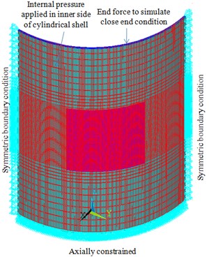
No analytical formulae can be established for profile deviated geometry type problems. The only way is to solve by properly modeling it in finite elements to capture the exact realistic behavior. An extensive 3D FE model is made using the extracted coordinates through profile measurement at and around the hoop strain difference location (defect location). Along with the defect location, a sufficient generic cylindrical region and a transition region which patches both the defect and generic regions is generated to simulate the realistic boundary conditions (Fig. 3).
Fig. 3a) FE model of measured profile of cylindrical pressure vessel with generic cylindrical shell b) measured profile of cylindrical shell (230 mm×250 mm), c) a small region of profile showing waviness / kink
a)
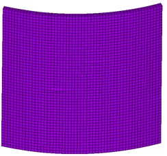
b)

c)
Entire geometry meshes with 8 noded Brick elements. Two elements across thickness are idealized. Model is constrained in the axial direction at one axial surface and on the other axial surface, the theoretical longitudinal stress is applied to simulate the closed end condition. The symmetry boundary condition is applied on both the circumferential free surfaces.
Internal pressure corresponding to a pressure of 120 ksc (11.772 MPa) is applied all along the inner surface. Non-linear material properties were generated based on the minimum guaranteed 0.2 % PS and UTS of the material properties (0.2 % proof strength = 834 MPa & ultimate tensile strength = 981 MPa). Geometric and material (using Eq. (5)) non-linear analyses were carried out using ANSYS finite element software [18]. This makes the study of this mathematical model of great significance to the comprehending and foretelling of materials behavior.
4. Experimental stress analysis
Keil and Benning [20] procedure used for the calculation of stresses from the measured strains. The stress components ( and ) for the measured strains ( and ) at the critical locations are evaluated from:
Here subscripts 1, 2, and 3 refer to the meridional, hoop and radial directions of the steel tank. When the vessel is subjected to the internal pressure (), the stress normal to the surface or the radial stress () is, at inner surface:
and at outer surface:
The radial strain () not possible to measure can be obtained from:
The Lame’s coefficients ( and ) are:
Within elastic range, the stress components ( and ) for the measured strains ( and ) at the applied pressure () can be obtained from Eq. (8-12), using the material constants and . To carry out elasto-plastic stress analysis, an equivalent strain () is determined from:
The stress () corresponding to the strain () is obtained from Eq. (5). The secant modulus () and the secant Poisson’s ratio () are:
Replacing and by and in Eq. (8-12), one can get the principal stresses ( and ) for the measured strains ( and ). The following iterative process is considered to evaluate and . Initially, is assumed as and obtain from Eq. (13) for the measured strains ( and ) at the applied pressure (). Later on corresponding to is found from Eq. (5). These values are substituted in Eqs. (14-15) to obtain and . This iterative process is continued until attains a converged value. Using the secant modulus () and the secant Poisson’s ratio () for the measured strains ( and ), the respective principal stresses ( and ) are obtained from Eq. (8-12).
5. Results and discussion
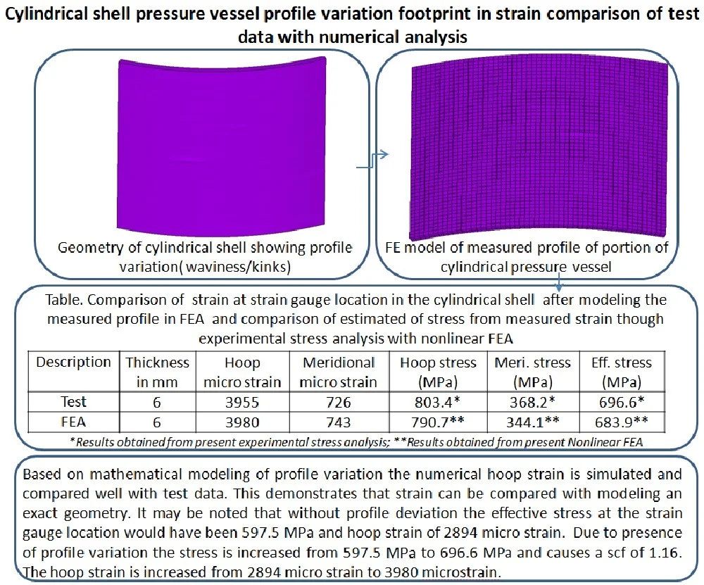
A finite element model is generated using ANSYS FEA including the measured 3D profile variation, and non-linear (NL) analysis has been performed. The results away from profile deviation (cylindrical shell without waviness or kink) and near profile deviation with a waviness in cylindrical shell are shown. The values of membrane meridional stress (343 MPa), hoop stress (690 MPa) and effective stress (597.5 MPa) noted away from the defect region (in the generic cylindrical region) matches closely with the theoretically expected values (hoop stress = 686 MPa, meridional stress = 343 MPa and effective stress = 594 MPa) which validates the loads and boundary conditions. Hoop stress, meridional stress, and effective stress variations are plotted in Figs. 4-6 respectively. The margin of safety with respect to yield strength of the material is [(834/597.5) –1.0] = 0.395.
The longitudinal stress, hoop stress, and internal pressure were determined from equations of generalized Hooke’s law for stress and strain. The meridional strain ( 667 microstrain) and hoop strain ( 2833 microstrain) are found. These strains compared well with FEA having meridional strain ( 674 microstrain) and hoop strain ( 2894 microstrain). The hoop and meridional strain plots are shown in Fig. 7 and Fig. 8 respectively. The results are also presented in Table 1. So the analytical strain mates closely with FEA.
The elastic strains ( and ) of the external surface of the cylindrical shell were determined through strain gages attached to the surface and connected to a strain indicator. The measured strain in the hoop direction is found to be 3955 microstrains. So, there is a large difference of around 1061 microstrain is observed in hoop direction as compared to analytical/FEA values of 2894 microstrain.
Fig. 4Hoop stress (MPa) in the cylindrical shell away from defect region
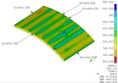
Fig. 5Meridional stress (MPa) in the cylindrical shell away from defect region
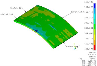
Fig. 6Effective stress (MPa) in the cylindrical shell away from defect region
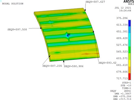
Fig. 7Hoop strain (2894 microstrain) in the cylindrical shell away from defect region
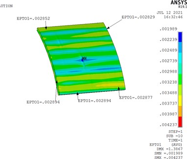
Fig. 8Meridional strain (674 microstrain) in the cylindrical shell away from defect region
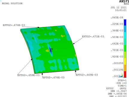
Fig. 9The maximum hoop strain (3980 microstrain) in cylindrical shell near the defect location
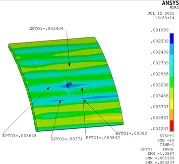
Fig. 10Maximum effective stress (MPa) in cylindrical shell near defect region
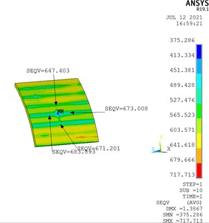
Table 1Stress and strain in the cylindrical shell without defect in profile (Bracket values are from analytical formulae). Meri. (Meridional); Eff. ( Effective)
Thickness in mm | Hoop micro strain (analytical) | Meridional micro strain (analytical) | Hoop micro strain (FEA) | Meridional micro strain (FEA) | Hoop stress (MPa) | Meri. stress (MPa) | Eff. stress (MPa) |
6 | 2833 | 667 | 2894 | 674 | 690 (686) | 343 (343) | 597.5(594) |
To find out the reason behind the strain difference, the profile of the cylindrical shell is modeled in Ansys. The corresponding hoop strain contour is shown in Fig. 9. The hoop strain is found at the waviness/dent or defect location is found to be 3980 microstrains and compared well with test hoop strain of 3955.
Experimental methods are useful for the correctness of the analytical or computational analysis. Usually, stress cannot be measured directly, and hence most experimental methods serve to measure strains by bonding the strain gauges to the surface of the structure under test. For the calculation of stresses from the measured strains, Keil & Benning [20] have described the analytical method for which Rao [19] suggests a simplified step that can be easily coded on a digital computer or Microsoft XL sheet. This approach (experimental stress analysis) was successfully applied to estimate stress from measured strain [11], [15].
The effective stress calculated based on the experimental stress analysis procedure is found to be 696.6 MPa. This stress is compared well with effective stress found by modeling the profile of cylindrical shells. The effective stress is found at the waviness/defect region of 683.9 MPa. The comparison is presented in Table 2. The margin of safety with respect to yield strength of the material is [(834/696.3) –1.0] = 0.19. This shows a positive margin against the yield strength of the material and meets the acceptance criteria. However, the margin safety is reduced from 0.395 to 0.19 due to the presence of profile variation. It may be noted that without profile deviation the effective stress at the strain gauge location would have been 597.5 MPa. So there is around a 99 MPa stress increase is there due to a change in profile. So there is an SCF of 1.16 is exist due to the presence of profile variation in the cylindrical shells.
Table 2Stress and strain in the cylindrical shell with waviness or kink/defect profile
Description | Thickness in mm | Hoop micro strain | Meridional micro strain | Hoop stress (MPa) | Meri. stress (MPa) | Eff. Stress (MPa) |
Test | 6 | 3955 | 726 | 803.4* | 368.2* | 696.6* |
FEA | 6 | 3980 | 743 | 790.7** | 344.1** | 683.9** |
*Results obtained from present experimental stress analysis **Results obtained from present NL FEA | ||||||
6. Conclusions
This paper shows the effect of profile variation in the membrane region of the thin cylindrical shell which causes strain difference between FEA and test. The experimental tests with the application of strain-gauge measurements and numerical modeling of the pressure vessel are conducted. Non-linear finite element analyses were carried out including the effects of 3D profile variation at the cylindrical shell region having fabrication deviation (waviness/kink). Based on mathematical modeling profile variation the numerical hoop strain is simulated is compared well with test data. This demonstrates that strain can be compared with modeling an exact geometry. This is a difficult problem in terms of modeling the profile of cylindrical shells in FEM. Once modeling is done appropriately, the results are derived from FEA and compared well with test data. Non-linear stresses in both hoop and meridional directions are extracted at the defect or strain difference location and compared with analytical stress based on experimental stress analysis on the measured strain. Further, it is found that due to presence of profile deviation causes additional bending stress. So it works out that the membrane region which supposes to give exact closed-form results can deviate from exact results due to the presence of profile variation. It will create bending in addition to the membrane which will cause stress or strain differences. The estimated stress from measured strain is found adequate margin by comparing the yield strength of material. This problem is a process of modeling the exact geometry in finite elements with available measured geometrical data. So no regularities of generalized conclusions could establish due to non-availability of enough data. However, the results can be used as a demonstration of the 3D modeling of the profile of pressure vessel for assessing the impact (stress concentration factor, reduction of margin of safety) of the defect on its stress state and its acceptance procedure for use in operational purposes of aerospace, chemical, oil & gas pipeline industries, etc., to avoid detrimental effects.
References
-
G. Towler and R. Sinnott, “Design of pressure vessels,” in Chemical Engineering Design, Elsevier, 2013, pp. 563–629, https://doi.org/10.1016/b978-0-08-096659-5.00014-6
-
L. E. Hayden and J. R. Sims, “Engineered pressure vessels for marine service using ASME section VIII, Division 2 and Division 3 pressure vessel codes,” in ASME/USCG 2010 2nd Workshop on Marine Technology and Standards, Jul. 2010, https://doi.org/10.1115/mts2010-0208
-
M. A. Khattak, A. Mukhtar, A. F. Rafique, and N. Zareen, “Reactor pressure vessel (RPV) design and fabrication: a literature review,” Journal of Advanced Research in Applied Mechanics, Vol. 22, No. 1, pp. 2289–7895, Jan. 2016.
-
A. S. Rao, G. V. Rao, and B. N. Rao, “Effect of long-seam mismatch on the burst pressure of maraging steel rocket motor cases,” Engineering Failure Analysis, Vol. 12, No. 2, pp. 325–336, Apr. 2005, https://doi.org/10.1016/j.engfailanal.2004.01.004
-
D. Davidson, K. Chan, R. Mcclung, and S. Hudak, Comprehensive Structural Integrity. 2003, pp. 129–161.
-
D. G. Jones and P. Hopkins, “The influence of mechanical damage on transmission pipeline integrity,” in Proceedings of the 1983 International Gas Research Conference, pp. 106–115.
-
A. J. Rinehart and P. B. Keating, “Stress concentration solution for a 2d dent in an internally pressurized cylinder,” Journal of Engineering Mechanics, Vol. 133, No. 7, pp. 792–800, Jul. 2007, https://doi.org/10.1061/(asce)0733-9399(2007)133:7(792)
-
M. R. Mitchell, “Fundamentals of modern fatigue analysis for design,” in Fatigue and Fracture, Vol. 19, ASM International, 1996, pp. 227–249, https://doi.org/10.31399/asm.hb.v19.a0002364
-
T. Chen, “On introducing imperfection in the non-linear analysis of buckling of thin shell structures,” 2014.
-
J. Ahmad Fahmy, “Flow equations in commercial gas piping system,” Faculty of Chemical and Natural Resources Engineering, Universiti Malaysia Pahang, 2010.
-
Chitaranjan Pany, Malli Krishnamoorthy Sundaresan, B. Nageswara Rao, Bhagavatheeswara Sivasubramonian, and N. Jayachandran, “On the bursting of an HSLA steel rocket motor case during proof pressure testing,” Steel Grips (Journal of Steel and Related Material) Application, Vol. 10, pp. 434–438, Oct. 2012.
-
Merlin J. Thattil and Chitaranjan Pany, “Design and analysis of pressure vessel with different end domes,” International Journal of Science Engineering and Technology Research, Vol. 6, No. 8, pp. 1225–1233, Aug. 2017.
-
Sreelakshmi M. G. and Chitaranjan Pany, “Stress analysis of metallic pressure vessels with circumferential mismatch using finite element method,” International Journal of Scientific and Engineering Research, Vol. 7, No. 4, pp. 479–484, Apr. 2016.
-
Chitaranjan Pany, “Structural analysis of metallic pressure vessels with weld sinkage in the circumferential joint,” Zenodo, Vol. 2, No. 1, pp. 4–10, Jun. 2021, https://doi.org/10.5281/zenodo.4586360
-
Chitaranjan Pany, “Estimation of correct long-seam mismatch using FEA to compare the measured strain in a non-destructive testing of a pressurant tank,” International Journal of Smart Vehicles and Smart Transportation, Vol. 4, No. 1, pp. 16–28, Jan. 2021, https://doi.org/10.4018/ijsvst.2021010102
-
J. F. Harvey, Theory and Design of Pressure Vessels. New York, USA: Van Nostrand Reinhold Company Inc, 1985.
-
Z. Huda and Muhammad Hani Ajani, “Evaluation of longitudinal and hoop stresses and a critical study of factor of safety (fos) in design of a glass-fiber pressure vessel,” World Academy of Science, Engineering and Technology [Materials and Metallurgical Engineering], Vol. 9, No. 1, pp. 39–42, 2015, https://doi.org/10.5281/zenodo.1338082
-
ANSYS Software Version 14.0 Documentation.
-
B. N. Rao, “A simplified procedure for stress analysis in the elasto-plastic range with the aid of strain gages,” Experimental Techniques, Vol. 15, No. 3, pp. 38–39, May 1991, https://doi.org/10.1111/j.1747-1567.1991.tb01179.x
-
S. Keil and O. Benning, “On the evaluation of elasto-plastic strains measured with strain gages,” Experimental Mechanics, Vol. 19, No. 8, pp. 265–270, Aug. 1979, https://doi.org/10.1007/bf02324285
Cited by
About this article

