Abstract
Based on bilinear hardening material model, the swage autofrettage technology of steel sleeve for pump is analyzed. The theoretical calculation formulas of stress, strain, residual stress and strain and punch thrust of swage autofrettage steel sleeve are derived by the elastic-plastic analysis. The accuracy of the theoretical formulas is verified by the swage autofrettage experiment. The result of theoretical calculation is consistent with that of the experiment, and the process of the second loading does not affect the autofrettage result. The theoretical calculation formulas can be used to guide the swage autofrettage technology design of the steel sleeve for the pump.
Highlights
- A set of theoretical calculation formulas of swage autofrettage of the steel sleeve for the pump are proposed.
- If the size of the steel sleeve with autofrettage and the circumferential resultant stress are known, the equations of the autofrettage theory can be used as a reference for the design of swage autofrettage of the steel sleeve for the pump to obtain the size of the punch and the steel sleeve before autofrettage.
- The experimental device of the swage autofrettage of the steel sleeve for the pump has been designed.
- It is found that the residual strain after the second loading process is the same with that of the first process.
1. Introduction
High pressure plunger pump is widely used in high pressure water jet cleaning, hydraulic demolition and other fields, more and more manufacturing enterprises begin to design and manufacture high pressure plunger pump. The mass production of high pressure plunger pump promotes the rapid development of high pressure water jet technology [1]-[2]. The plunger pump depends on the reciprocated movement of the plunger in the cylinder, so that the volume of the sealing working chamber is changed, so as to realize the suction and discharge of liquid [3]. The steel sleeve is the main load bearing element of the high pressure plunger pump, which is vulnerable to fatigue fracture. Frequent replacement of the steel sleeve will affect the engineering efficiency, therefore, it is particularly important to improve the fatigue life of the steel sleeve in the process of design.
The thick-walled cylinder treated by the autofrettage technology has the merits of well-distributed stress, low average stress and high fatigue life. Therefore, by using this treatment, the working stress amplitude of the steel sleeve can be reduced and the fatigue life of the steel sleeve can be improved [4]-[5]. The swage autofrettage is to use the punch with a certain amount of interference to extrude the inner wall of the steel sleeve, in order to produce plastic deformation and generate residual compressive stress.
In the earlier study on swage autofrettage, the calculation of swage autofrettage problem is based on the formulas of hydraulic autofrettage [6]. The elastic-plastic problem of thick-walled cylinder is analyzed based on bilinear hardening material model [7]. However, the formulas have difficulties to solve the actual problem of swage autofrettage of the steel sleeve for the pump. In addition, the unloading process is considered without reverse yield, the theoretical calculation formulas could be further simplified so as to solve quickly.
In this paper, based on bilinear hardening material model and considering the elastic unloading process without reverse yield, the theoretical calculation formulas of stress, strain, residual stress and strain and punch thrust of the steel sleeve are derived. The swage autofrettage experiment is designed to verify the accuracy of the theoretical calculation formulas by measuring the outer wall strain value of the steel sleeve. The result shows that the relative error is less than 10 %. Therefore, the value of the theoretical calculation is basically consistent with that of the experiment.
2. Theoretical calculation model and mechanical analysis
The process of swage autofrettage is a space axisymmetric elastoplastic mechanics problem with moving contact [8]. The theoretical analysis of this kind of problem is very complicated. In order to solve the problem, the following simplified assumptions should be made:
(1) It is based on the bilinear hardening material model with the same elastic modulus and hardening modulus for loading and unloading. The material constitutive relation is shown in Fig. 1.
(2) The axial strain at each point on the cross section of the steel sleeve is same.
(3) Biconical cylindrical punch is widely used [9]. Due to the same amount of interference and the short length of cylindrical section, it is approximately considered that the stress in this section does not change along the -axis, and the elastic-plastic boundary radius is a constant.
(4) If is assumed to be intermediate stress, according to the Tresca’s yield criterion, the material satisfies the yield condition and meets the condition in the loading plastic zone. In addition, assume that the relationship is valid in the whole plastic zone .
Fig. 1Material constitutive relations of bilinear hardening material
In this paper, according to the working requirements of the steel sleeve for the pump, the following conditions should be met in the process of swage autofrettage of steel sleeve:
(1) The steel sleeve needs to produce a certain plastic deformation in the loading process of swage autofrettage, but the whole steel sleeve cannot reach a fully plastic state, that is, part of the section of the outer wall of the steel sleeve does not yield.
(2) The unloading process of the steel sleeve is elastic unloading, and no reverse yield occurs in this process.
In the elastic-plastic analysis of the steel sleeve for the pump, the steel sleeve can be regarded as a thick-walled cylinder. Based on the simplified assumptions mentioned above, the stress of the steel sleeve satisfies the following equilibrium equation:
The strain component can be divided into the elastic part and the plastic part, that is , and the elastic part satisfies the Hooke’s law as follows:
According to the condition of the loading plastic zone, , and the plastic flow rule in hypothesis Eq. (4), the plastic strain without initial strain can be obtained as follows:
When the volume incompressibility condition is considered and combined with Eq. (3-4), the equivalent plastic strain factor can be expressed as follows:
If assume that the volume deformation is elasticity, there exists , which could also be written as follows:
Substitute into Eq. (1), the equations of the elastic-plastic strain and circumferential plastic strain of the steel sleeve are obtained as follows:
3. Elastic-plastic analysis of loading process
A loading process occurs, when the steel sleeve has an interference contact with the punch. In this process, the steel sleeve will produce a certain amount of plastic deformation. According to the condition Eq. (1) based on the working requirements, there will be a part of elastic section plus a part of plastic section, so assume that is the elastoplastic boundary. At this boundary, the stress satisfies the continuity condition, in the other words, the equation of the stress of the elastic zone will be the same with that of the plastic zone.
3.1. Stress and strain of loading process in the elastic zone ()
The stress calculation equation of steel sleeve in the elastic zone of loading process can be obtained from Eq. (1-2) and geometric conditions:
where, , are undetermined constants.
The steel sleeve at the elastoplastic boundary just meets the yield condition. According to the Tresca’s yield criterion and the assumption Eq. (4), there is at the elastoplastic boundary.
At the same time, the radial stress on the outer wall of the steel sleeve should be zero, that is, there is a boundary condition in the elastic zone of loading process: , .
According to the above conditions and the hypothesis Eq. (4), the undetermined constants and can be obtained and the stress calculation formulas of the steel sleeve in the elastic zone of loading process is:
Based on Eq. (2), geometric relations and the above stress calculation formulas Eqs. (12-14), the strain calculation formulas in the elastic zone of loading process can be derived as follows:
3.2. Stress and strain of loading process in the plastic zone ()
In the elastic zone of loading process, the plastic strain is zero. The following equation can be obtained by combining Eq. (9) with the derivative of Eq. (12):
According to the hypothesis Eq. (4) and Eq. (1), the following equation can be obtained:
It can be obtained by combining the Eqs. (5, 9, 18, 19) as follows:
where, .
According to the continuity condition at the elastoplastic boundary, the stress calculation formulas are derived as follows by integrating the equation, which is obtained by substituting Eq. (20) into Eq. (19):
According to Eqs. (7, 8, 17, 18, 19, 21), the strain calculation formulas of loading process in the plastic zone are derived as follows:
According to Eq. (3), the axial strain of loading process in the plastic zone is the same as that in the elastic zone as follows:
3.3. Analysis of the axial force and solution of the undetermined constant
The axial force of the steel sleeve is the sum of the force of the cylindrical section of the punch and the front cone of the punch:
The resultant force at the end of the cylindrical section of the punch can be expressed as follows:
The resultant force of the cylindrical section of the punch is composed of the resultant force of friction:
where,
The resultant force of the front cone is composed of the pressure and frictional force:
where,
Substituting Eqs. (28-30) into Eq. (27), the expression of is obtained as follows:
4. Elastic-plastic analysis of unloading process
According to the condition Eq. (2), the unloading process of the steel sleeve is elastic unloading, and no reverse yield occurs in this process [10].
4.1. Stress and strain of unloading process
According to Eqs. (1-2) and geometric conditions, the following equations can be obtained:
where, , are undetermined constants.
According to the mechanical analysis, the stress of unloading process at the inner wall of the steel sleeve should be equal to that of the loading process, that is, . There is a boundary condition that the radial stress on the outer wall is zero, . From the above conditions, the stress calculation formulas are derived as follows:
where,
According to Eq. (2), geometric relations and the stress calculation formulas Eq. (34-36), the strain calculation formulas are derived as follows:
4.2. Residual stress and strain and radial residual expansion
The residual stress of the steel sleeve with autofrettage is equal to the difference between the stress of loading and unloading process:
The residual strain is equal to the difference between the strain of loading and unloading process:
The radial residual expansion of the steel sleeve is the difference between the displacement of the inner wall of the steel sleeve of loading and unloading process:
Substituting the Eqs. (24, 37) into Eq. (42), the radial residual expansion of the steel sleeve can be derived.
4.3. Circumferential resultant stress of the steel sleeve in working condition
Under working condition, the steel sleeve bears pulsating pressure and the circumferential resultant stress of the steel sleeve with autofrettage is composed of the working stress and residual stress [11] as follows:
According to the Lame formula, the circumferential stress on the inner wall of the steel sleeve () caused by working pressure can be expressed as follows [12]:
In the above equation, is the radius size of the inner wall of the steel sleeve with autofrettage. It can be derived by the following formula:
Substituting Eqs. (22, 35) into Eq. (40), the circumferential residual stress of the inner wall of the steel sleeve with autofrettage can be obtained as follows:
Substituting Eqs. (44, 46) into Eq. (43), the circumferential resultant stress can be derived. If the size of the steel sleeve with autofrettage and the circumferential resultant stress are known, the size of the steel sleeve before autofrettage and the punch will be obtained by substituting the equations of the swage autofrettage theory. Thus, the equations of the autofrettage theory can be used as a reference for the design of swage autofrettage of the steel sleeve for the pump.
5. Punch thrust
The rear cone angle of the punch is approximately equal to the frictional angle, so the influence of the rear cone angle on the punch thrust can be ignored:
The punch thrust can be obtained from the equilibrium condition of the axial force of the punch as follows:
6. Example calculation and experimental analysis of swage autofrettage
6.1. Design of swage autofrettage experiment of the steel sleeve and data processing
In order to verify the accuracy of the theoretical calculation formulas, a swage autofrettage experiment of the steel sleeve for the pump was designed in this paper. The experimental steel sleeve was made of 304 stainless steel and the experimental punch adopted the form of biconical cylinder with 15-5PH material. In this experiment, the circumferential strain of the outer wall of the steel sleeve was measured to be compared with the theoretical calculation value.
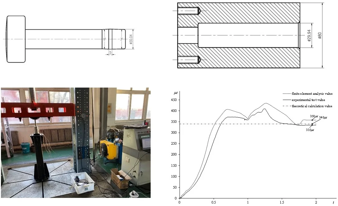
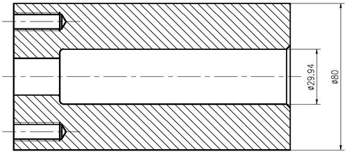
The front cone angle of the punch is usually designed as 1.5 degrees [13]-[15]. If the angle is too large or too small, the punch thrust will increase. In this paper, the biconical cylindrical experimental punch was composed of a front cone angle of 1.5 degrees and a rear cone angle of 3 degrees. The structure diagram of the experimental punch was shown in Fig. 2. The structure of the experimental steel sleeve simulated the steel sleeve for the pump with the structure of stepped hole. The structure diagram of the experimental steel sleeve was shown in Fig. 3. The processing surface of the steel sleeve was at the place where the diameter was larger, the punch could not pass through the stepped hole. Therefore, there were two processes in this experiment, which were the punch pressing in and exiting from the same side of the steel sleeve.
The swage autofrettage experimental device was designed by taking advantage of the pressure experimental platform, as shown in Fig. 4. A four-channel strain gauge was used to collect the strain of the outer wall of the steel sleeve. The strain gauge was attached to the outer wall surface of the experimental steel sleeve every 90 degrees and every 30 mm from the top of the steel sleeve. The cylindrical coordinate system was established with the center of the upper end-face of the steel sleeve as the origin and the -axis positive direction from the top to the bottom. The four data collection points could be expressed as (40, 0, 0) (40, 90, 30) (40, 180, 60) (40, 270, 90) from the top to the bottom in cylindrical coordinate system.
Fig. 2Structure diagram of the experimental punch
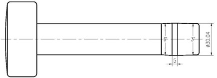
Fig. 3Structure diagram of the experimental steel sleeve
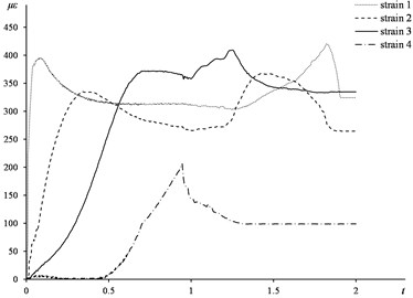
After data processing, the time-strain curve graph was shown in Fig. 5. The four data collection points from the top to the bottom were strain 1 to strain 4 in turn.
Fig. 4Swage autofrettage experimental platform
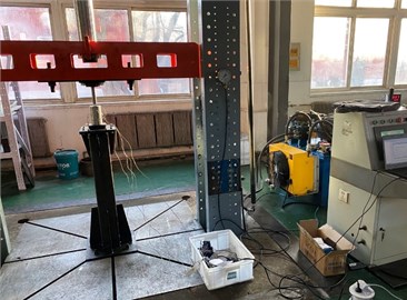
Fig. 5Time-strain curve of experimental test
6.2. Finite element analysis
According to the size and material of the punch and steel sleeve in the swage autofrettage experiment, the material of the punch and the steel sleeve were set as 15-5PH and 304 stainless steel respectively in finite element analysis. The mechanical property parameters of 304 stainless steel and 15-5PH material were shown in Table 1.
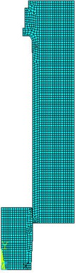
The plane axisymmetric model was used and it was meshed as shown in Fig. 6. The displacement constraint was applied to one end of the steel sleeve, at the same time, two loading steps were applied to the punch, pressing in and exiting respectively.
Table 1Mechanical property parameters of 304 stainless steel and 15-5PH material
Parameters | Value | unit |
Elastic Modulus of 304 () | 193000 | MPa |
Elastic Modulus of 15-5PH () | 198000 | MPa |
Poisson ratio of 304 () | 0.3 | |
Poisson ratio of 15-5PH () | 0.272 | |
Yield strength of 304 () | 250 | MPa |
Hardening coefficient of 304 () | 0.1762 | |
Friction coefficient () | 0.05 |
Fig. 6The finite element model
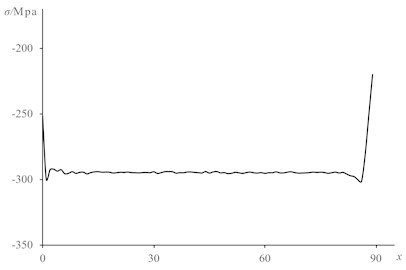
The time-strain curve graph of the steel sleeve at the four data collection points were shown in Fig. 7. The circumferential residual stress of the steel sleeve in the inner wall varied along the axis as shown in Fig. 8 and the average value from the position of the first data collection point to the fourth data collection point was – 295 MPa.
Fig. 7Time-strain curve of finite element analysis
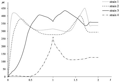
Fig. 8Circumferential residual stress of the steel sleeve along the axis
6.3. Theoretical calculation and relative error analysis
When there is the condition , substituting Eqs. (15, 37) into Eq. (41), the circumferential residual strain of the outer wall of the steel sleeve can be derived as follows:
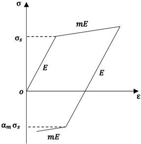
Based on the size and material parameters of the experimental punch and steel sleeve and according to the theoretical calculation formulas Eq. (49), the theoretical calculation value of the residual strain on the outer wall of the steel sleeve is 340×10-6.
The following conclusion can be found through comparing the time-strain curve of experimental test and finite element analysis:
(1) The time-strain experimental curve of the top three data collecting points appear two peaks, that is because there are two processes, pressing in and exiting from the same side. Therefore, there will be two loading processes except of the fourth data point. Since it only occurs elastic deformation in the second loading process, the residual strain after the second loading process is the same with that of the first process.
(2) The time-strain curve of the fourth strain point does not appear two peaks and the strain value is significantly lower than the other three points, that is because the cylinder section of the punch does not reach the fourth strain point in the experiment. The residual strain is smaller due to the smaller amount of interference.
(3) The strain value of the first point is larger, that is because this point is close to the edge of the steel sleeve where the constraint is less.
(4) The trend of the experimental curve is the same as that of the finite element curve, and the values are close. Therefore, both of the experimental value and the finite element value are reliable and can be used to judge the accuracy of the theoretical calculation method.
Fig. 9Time-strain curve of theoretical calculation, finite element analysis and experimental test
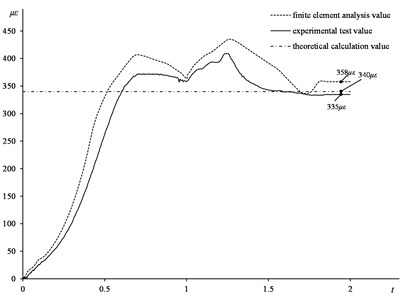
Based on the above conclusions, considering that the effect of the end restraint is ignored in the theoretical calculation model and the first and second data collection points are close to the end of the steel sleeve, the third data collection point is the most consistent with the theoretical calculation model. Therefore, the time-strain curve of theoretical calculation and finite element analysis at the third point are selected to compare with the theoretical calculation value. Because the theoretical calculation result is the value of residual strain, the theoretical calculation value is a time-independent constant. The time-strain curve of theoretical calculation, finite element analysis and experimental test are shown in Fig. 9.
Based on the curve above, the relative error of theoretical calculation and experimental test is about 1.5 %, and the relative error of theoretical calculation and finite element analysis is about 5 %, so the value of theoretical calculation is consistent with the experimental test and finite element analysis. Therefore, the theoretical calculation method can be applied in engineering practice.
When there is the condition , substituting Eqs. (22, 35) into Eq. (40), the circumferential residual stress of the inner wall of the steel sleeve can be derived as follows:
Based on the size and material parameters of the experimental punch and steel sleeve and according to the theoretical calculation formulas Eq. (50), the theoretical calculation value of the residual stress on the inner wall of the steel sleeve is –260 MPa.
It is difficult to measure the residual stress on the inner wall of the steel sleeve by the existing residual stress measurement methods, so the finite element result can be used to judge the accuracy of the theoretical calculation method. Compared with the average value of finite element analysis, the relative error is about 10 %, so the value of theoretical calculation is basically consistent with the finite element analysis.
The causes of the error between theoretical calculation and finite element analysis are as follows:
(1) The theoretical calculation model ignores the effect of the end restraint.
(2) The theoretical calculation model is based on semi-infinite space.
Both of the theoretical analysis and the experimental results show that the plastic deformation of the steel sleeve occurs during the loading process, and the elastic unloading occurs during the unloading process. The residual compressive stress is generated on the inner surface of the steel sleeve at the position where the punch passes. In the punch exiting process, the size of the punch does not change, so the steel sleeve in this process does not produce plastic deformation, and it will not affect the results. It can be seen from the experimental curve that the residual strain value after the punch exiting process is the same with that after the first loading process. Therefore, the above theoretical calculation method of swage autofrettage of the steel sleeve for the pump can be the reference of the design.
7. Conclusions
In this paper, the theoretical research and experimental verification of swage autofrettage of the steel sleeve for the pump are carried out, and the following conclusions are drawn:
1) A set of theoretical calculation formulas of swage autofrettage of the steel sleeve for the pump are obtained through elastic-plastic analysis, and the accuracy of the formulas is verified by the experiment. This set of formulas is simple and can be used to guide the swage autofrettage process of the steel sleeve for pump.
2) The theoretical calculation formula of the punch thrust is obtained through mechanical analysis. It can be the reference for engineering application.
3) There are two processes of swage autofrettage of the steel sleeve for the pump, the punch pressing in and exiting from the same side. The theoretical analysis and experimental results show that it is elastic loading during the exiting process, so it will not affect the swage autofrettage result and the theoretical calculation formulas are still valid.
4) If the size of the steel sleeve with autofrettage and the working pressure is known, according to the stress requirement in the inner wall of the steel sleeve, the size of the steel sleeve before autofrettage and the punch will be obtained by substituting the equations of the swage autofrettage theory. Thus, the equations of the autofrettage theory can be used as a reference for the design of swage autofrettage of the steel sleeve for the pump.
References
-
J. Ren, “Application and development trend of high pressure water jet cleaning technology,” (in Chinese), Cleaning World, Vol. 35, pp. 60–61, 2019.
-
X. R. Cheng, S. Y. Zhang, L. L. Ma, and Y. T. Luo, “The application status and development prospects of high pressure water jet technology,” (in Chinese), Hydraulics Pneumatics and Seals, Vol. 39, No. 8, pp. 1–6, 2019.
-
Design of Reciprocating Pump. (in Chinese), Beijing, China: Mechanical Industry Press, 1987.
-
J. M. Alegre, P. Bravo, and M. Preciado, “Fatigue behaviour of an autofrettaged high-pressure vessel for the food industry,” Engineering Failure Analysis, Vol. 14, No. 2, pp. 396–407, Mar. 2007, https://doi.org/10.1016/j.engfailanal.2006.02.015
-
J. M. Alegre, P. M. Bravo, and I. I. Cuesta, “Fatigue design of wire-wound pressure vessels using ASME-API 579 procedure,” Engineering Failure Analysis, Vol. 17, No. 4, pp. 748–759, Jun. 2010, https://doi.org/10.1016/j.engfailanal.2009.08.008
-
M. J. Iremonger and G. S. Kalsi, “A numerical study of swage autofrettage,” Journal of Pressure Vessel Technology, Vol. 125, No. 3, pp. 347–351, Aug. 2003, https://doi.org/10.1115/1.1593073
-
J. C. Wang and B. Y. Xu, “An elasto-plastic analysis of mechanically autofretted thick-walled cylinders with bilinear materials,” (in Chinese), Shanghai Mechanics, Vol. 16, No. 2, pp. 109–120, 1995.
-
L. Z. Chang, Y. T. Pan, and K. W. Li, “Residual stress analysis of gun barrel with bi-linear material model,” (in Chinese), Acta Armamentarii, Vol. 34, No. 4, pp. 385–391, 2013.
-
L. G. Pan, “On theoretical and experimental investigations of autofrettage,” (in Chinese), Tsinghua University, Beijing, China, 1988.
-
L. Z. Chang, Y. T. Pan, and X. M. Ma, “Residual stress analysis of mechanical autofrettage gun barrel,” (in Chinese), Journal of North University of China (Natural Science Edition), Vol. 36, No. 3, pp. 304–310, 2015.
-
Y. X. Zhang, H. Wang, and D. S. Chen, “Calculating the optimal radius of the elastic-plastic junction,” (in Chinese), Journal of Chongqing University, Vol. 27, No. 6, pp. 30–31, 2004.
-
M. Zhou, T. J. Lin, and J. Zhou, “Comparison of theory and numerical simulation for thick-walled cylinder autofrettage,” (in Chinese), Pressure Vessel Technology, Vol. 34, No. 6, pp. 14–18, 2017.
-
Y. K. Wang, J. X. Zhao, G. Z. Han, and F. Zhao, “Research on the shape of mechanical self-tightening punch based on numerical simulation,” (in Chinese), Machine Design and Manufacturing Engineering, Vol. 48, No. 12, pp. 21–24, 2019.
-
J. C. Wang and B. Y. Xu, “Research on the mandrel push force and mandrel shape design in mechanical autofrettage of thick-walled cylinders,” in Proceeding of Second Asia-Pacific Symposium on Advances in Engineering Plasticity and Its Application, 1994.
-
B. Y. Xu, J. B. Rui, and J. C. Wang, “Theoretical and experimental investigation of autofrettage problems,” in Proceeding of Second Asia-Pacific Symposium on Advances in Engineering Plasticity and Its Application, 1994.
About this article

