Abstract
Based on the requirement of physical experiments, a ultra-high pressure control system which consisted of servo valves, a booster cylinder, and a multi-channel synchro-loading control system, was designed. A multi loop control strategy was adopted in this system, and hydraulic oil was loaded on the low-pressure side of the booster cylinder. In this way, the high precision control of low pressure increasing with high flow was attained, either was ultra-high pressure increasing, maintaining and reducing with low flow. The system was applied in a landing gear strength test successfully, the pressure control accuracy was smaller than 0.5 %, and the test task was completed satisfactorily.
Highlights
- Low cost, good system compatibility and stable high pressure is achieved by adopting low pressure hydraulic components
- By giving full play to the role of low-pressure servo components in controlling ultra-high pressure accurately, the problem that the high-pressure with low flow cannot be accurately controlled is solved
- The pressurization, pressure maintaining and pressure reduction of ultrahigh pressure equipment are realized
1. Introduction
The working pressure of the hydraulic system in engineering applications is usually about 20 MPa, which can meet most of the requirements generally and is easy to use and maintain [1]. In some engineering fields, the working pressure of equipment exceeds 32 MPa, which is called ultra-high pressure.
In order to achieve the goal of weight reduction, the hydraulic system of the aircraft adopts high pressure and ultra-high-pressure technology always. If the rated working pressure of the hydraulic system is increased from 21 MPa to 28 MPa, the weight of the actuator is reduced by about 8 %, the weight of the working fluid is reduced by about 21 %, and the total weight of the hydraulic system is reduced by 5 % [2]. In a landing gear static strength test of an aircraft, it is demanded to apply oil pressure to the actuating cylinder. Pressure in the test reaches 43 MPa, considering the design safety factor1.5 [3-4].
In previous pressure tests, a hand pump is often used manually for loading, which may lead to problems of slow pressurization speed, low control accuracy and prominent potential safety hazards, and cannot be applied to fatigue tests. The ultra-high pressure hydraulic system is widely used in hydraulic tools and forging industry, which do not require precise control of pressure, nor can they set a control protection limit. It does not match the requirements of an aircraft static test [5-9]. Yang Hu realized high pressure (52 MPa) loading by carrying out pressurization transformation on a hydraulic system, but the automation degree of the system is limited, and the operation is relatively cumbersome [10]. Zhipeng Zhang et al. designed an ultra-high pressure automatic control system, which can achieve high pressure not greater than 120 MPa, but the interference problem limits its application, either the low acquisition frequency and low control accuracy [11].
Aiming at improving the control ability of ultra-high pressure, an ultra-high pressure device was designed, which composed of a low-pressure servo pump, servo valves and a booster cylinder. The precise loading control of ultra-high pressure became reality by combining the device with the existing control system and hydraulic system. The system has the following advantages:
1) Low cost, good system compatibility and stable high pressure is achieved by adopting low pressure hydraulic components;
2) By giving full play to the role of low-pressure servo components in controlling ultra-high-pressure accurately, the problem that the high-pressure with low flow cannot be accurately controlled is solved;
3) The pressurization, pressure maintaining, and pressure reduction of ultrahigh pressure equipment are realized.
2. System composition and working principle
2.1. System composition
At present, there are mainly two strategies to obtain ultra-high pressure: using ultra-high-pressure components to obtain ultra-high pressure directly or using low pressure hydraulic components and a booster cylinder to obtain ultra-high pressure. The former strategy is expensive, with high flow, high internal leakage, and low efficiency [12]. The control accuracy of the ultra-high pressure with low flow is poor, and it is hard to control when reducing the pressure, which failed to meet test requirements. So, the latter strategy is selected for its convenience and low energy consumption in this paper.
1) Control system.
MOOG16 multi-channel coordinated loading control system is selected, which adopts PID algorithm [13], and can set the value of parameters in the computer according to the requirements of force, displacement, or pressure. Servo valves were used to control the action of the hydraulic system, and the input parameters were converted into weak electrical signals through force, displacement, or pressure sensors. After signal conditioning and A/D conversion, the signals are sent to the main controller, then compared with the instruction value to perform compensation coordination. Finally, the collected data and control status are transmitted to the computer, and the interface displays the working condition of the loading device at that moment. The system can carry out out-of-tolerance and out-of-limit settings according to the test requirements and modify test parameters to obtain desired control results.
2) Hydraulic system.
The hydraulic system provides 21 MPa working pressure for the system. It is composed of oil source, a pump station, hydraulic pipeline, servo valves, etc. The hydraulic system has an unloading module that can unload the pressure to zero manually or automatically in case of an emergency.
3) Booster cylinder.
The booster cylinder is the core of the whole system, which is responsible for converting low pressure oil of the low-pressure hydraulic system into high pressure oil.
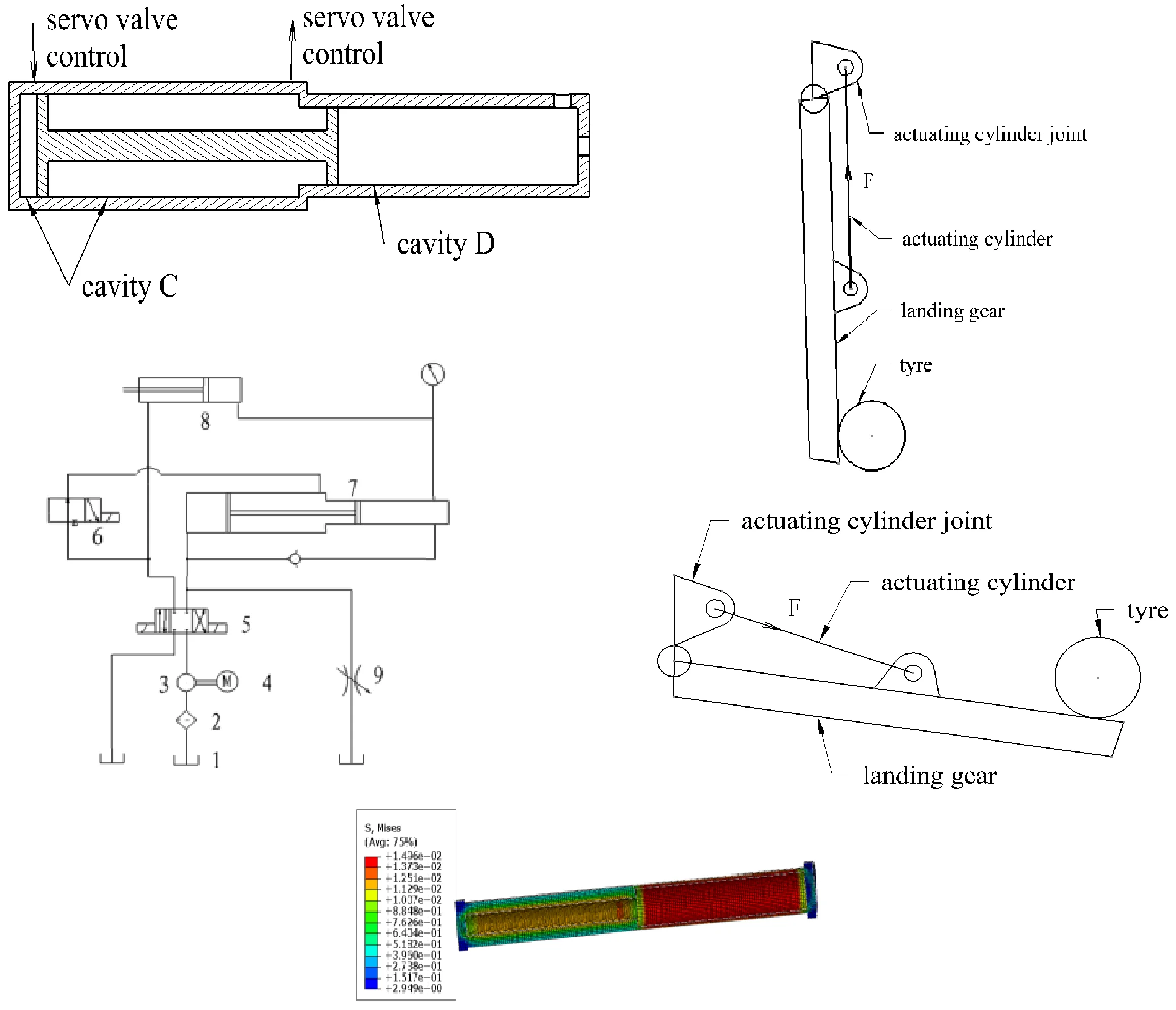
Fig. 1Diagram of the booster cylinder
The structure of the booster cylinder is shown schematically in Fig. 1. It includes a low-pressure cavity C and a high pressure cavity D. The piston areas at both ends of the piston rod are different. The piston diameter of cavity C is 140 mm, While the diameter of cavity D is 80 mm, and the piston rod stroke is 500 mm. When the low-pressure oil is input to cavity C, the high pressure will be generated in cavity D. The value of the supercharging ratio is 3:1, which is equal to the ratio of piston areas at both ends. Therefore, the working pressure of cavity C is 21 MPa, and that of cavity D is 63 MPa. Like low pressure hydraulic system, the medium of the system is No. 46 anti-wear hydraulic oil.
2.2. Working principle
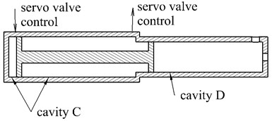
The working principle of the system is shown in Fig. 2.
When it is needed to raise the pressure, low-pressure oil output by the oil pump is pushed into the left rodless cavity of the booster cylinder through servo valve A, while hydraulic oil in the rod cavity of the booster cylinder flows back to the oil tank. By this way, the piston is pushed toward right, causing that cavity D and the actuating cylinder get high-pressure. At the same time, hydraulic oil in the rod cavity of the actuating cylinder flows back.
When it is needed to reduce the pressure, servo valve A reverses its direction, low-pressure oil output by the oil pump are pushed into the rod cavity of the booster cylinder through servo valve A and B, while hydraulic oil in the rodless cavity of the booster cylinder flows back to the oil tank. By this way, the piston retracts to the left, and the pressure of the actuating cylinder is reduced. At the same time, low pressure oil output by the oil pump enters the rod cavity of the retraction actuator to supplement oil to the rod cavity of the retraction actuator.
Before the test, a pressure sensor is connected to the pressurization cavity, so that flow of the servo valve can be controlled by the feedback of the sensor.
Fig. 2Diagram of pressurization circuit: 1 – oil tank, 2 – oil filter, 3 – oil pump, 4 – motor, 5 – servo valve A, 6 – servo valve B, 7 – booster cylinder, 8 – actuating cylinder, 9 – unloading valve
2.3. Calculation of the booster cylinder strength
In order to develop the potential for strength of the booster cylinder on the premise of safety, strength of the booster cylinder should be reasonably decided. Generally, the safety factor shall not be less than 5. The material of the cylinder is Quenching and tempering treatment 27SiMn, with tensile strength of 980 MPa and yield strength of 835 MPa. Main dimensions of the booster cylinder are shown in Table 1.
Table 1Main dimensions of the booster cylinder
Parameter | Size/mm |
Outside diameter of the booster cylinder’s low-pressure cavity | 160 |
Inner diameter of the booster cylinder’s low-pressure cavity | 140 |
Outside diameter of the booster cylinder’s high-pressure cavity | 160 |
Inner diameter of the booster cylinder’s high-pressure cavity | 80 |
Strength of the cylinder is calculated by the theoretical method and finite element simulation respectively as follows.
1) Theoretical calculation.
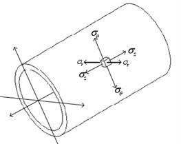
For a thick-walled cylinder, the cylinder is in a state of three-dimensional stress, including radial compressive stress , tangential tensile stress , and axial tensile stress , as shown in Fig. 3.
Fig. 3Stress analysis of thick-walled cylinder
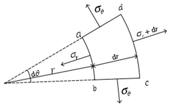
According to the thick-walled cylinder theory [14], the stress is calculated by the following formula:
where, – test pressure, – outside radius of the booster cylinder, – inner radius of the booster cylinder, – radius at any position of the cylinder, – .
It can be seen that the stress reaches the maximum on the inner wall of the cylinder, where . According to the fourth strength theory, the stress of the cylinder is as follows:
As a result, the following results are achieved:
Stress of the cylinder’s high-pressure cavity, 146 MPa, the factor of safety, 835/146 5.7.
Stress of the cylinder’s low-pressure cavity, 155 MPa, the factor of safety, 835/155 = 5.3.
2) Finite element simulation.
A finite element model of the pressurized cylinder was established in Abaqus. The model was discretized into 35188 elements, the main type of which is hexahedral linear reduction integration element C3D8R. The high-pressure cavity is loaded a pressure of 63 MPa, while pressure of the low-pressure cavity is 21 MPa.
The FEM results show that peak stress on the inner wall of the high-pressure cavity reaches 132.4 MPa, and the safety factor is 6.6, while peak stress on the inner wall of the low-pressure cavity reaches 149.6 MPa, with a safety factor of 5.6. The stress cloud picture is shown in Fig. 4.
It can be seen from the above analysis that the theoretical calculation results are close to the finite element analysis results, as shown in Table 2. The results demonstrate that the strength safety factor of the booster cylinder is greater than 5, which meets the strength requirement.
Fig. 4FEM results of the booster cylinder
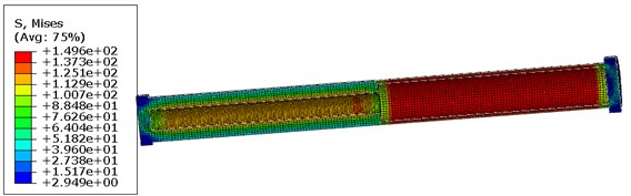
Table 2Comparison of stress results
Calculation method | Inner wall of the high-pressure cavity | Inner wall of the low-pressure cavity |
Theoretically calculated stress / MPa | 146 | 155 |
Finite element simulation / MPa | 132.4 | 149.6 |
3. The pressure test of the actuating cylinder
3.1. Test overview
During aircraft take-off and landing phases, the actuating cylinder is the main core component to control the retraction and extension of the landing gear [15]. The actuating cylinder is a two-force hinged support rod, one end of which is hinged to the main strut of the landing gear, and the other end of which is hinged to the wing (or fuselage). Extension and retraction of the piston are controlled by the hydraulic system of the aircraft.
During retraction and extension of the landing gear, the actuating cylinder joint on the wing is subjected to an axial force from the actuating cylinder. The joint is made of aluminum alloy and is connected with the wing by screws, so its strength is weaker than that of the landing gear and the actuating cylinder. Therefore, the structural strength of the joint and its diffusion area is necessary to be tested. The actuating cylinder has two working states: retracted state and extended state, which are shown in Fig. 5.
Fig. 5Diagram of a landing gear in retracted and extended states
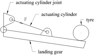
a) Retracted state
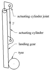
b) Extended state
Generally, the force shall be applied to the joint in the specified direction. But a loading actuator and a force sensor cannot be arranged in this test, due to the limitation of loading space. Therefore, pressurization directly in the actuating cylinder was considered, and the force value is calculated according to oil pressure and cross-sectional area of the piston, so as to achieve the purpose of checking the strength of the joint.
The oil circuit was connected as shown in Fig. 2 before the test. For retracted state of the landing gear, rod cavity of the actuating cylinder related to the booster cavity (cavity D shown in Fig. 1). For extended state of the landing gear, rodless cavity of the actuating cylinder related to the booster cavity.
Before the test, the actuating cylinder was disconnected from the connecting structure, and the booster cylinder was used to apply pressure to the working cavity of the actuating cylinder. When piston rod of the actuating cylinder was observed to move, the value of the pressure sensor was recorded, which was the starting pressure for the actuating cylinder. Then the value of the pressure sensor was set to zero.
The test was completed in the Full-Scale Aircraft Structure Static/Fatigue Aeronautic Science and Technology Laboratory, Aircraft Strength Research Institute of China. 100 % and 150 % limited load tests were carried out in retracted state and extended state of the landing gear, respectively. The test loading process was stable, and the control system worked well during the test.
According to the test load, pressure in the rodless cavity of the actuating cylinder in the 100 % limited load test is 28.98 MPa in extended state, and pressure in the rod cavity of the actuating cylinder in the 100 % limited load test is 28.98 MPa in retracted state.
3.2. Test results
High loading accuracy was obtained in the test, and the control accuracy of 100 % and 150 % limited load tests in both cases is shown in Table 3. In fact, the relative error is far less than 0.5 % in the whole process of the test.
Table 3Control accuracy of the test
Test case | Command value / kPa | Feedback value / kPa |
100 % limited load test in extended state | 28980 | 28980.8 |
150 % limited load test in extended state | 43470 | 43467.2 |
100 % limited load test in retracted state | 28820 | 28821.9 |
150 % limited load test in retracted state | 43230 | 43228.9 |
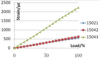
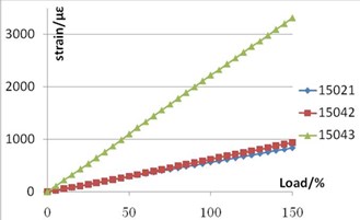
Six strain gages were pasted on the actuating cylinder joint to monitor stress state of the joint. Variation of strain with load obtained from the test are shown in Fig. 6 and Fig. 7.
Fig. 6Variation of strain with load in retracted state of the landing gear
a) 100 % limited load test
b) 150 % limited load test
Fig. 7Variation of strain with load in extended state of the landing gear

a) 100% limited load test
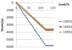
b) 150% limited load test
In the limited load tests of 100 % and 150 % in retracted state of the landing gear and 100 % limited load test in extended state, strain increased linearly with the load, and the maximum strain was below 5000 με. In the 150 % limited load test with the landing gear extended, strain increased linearly with the load before 120 % limited load, while the strain curve was basically flat after 120 % limited load, as shown in Fig. 7(b). It indicates that the load greater than 120 % was not transmitted to the actuating cylinder joint. The reason may be that the piston travel of the actuating cylinder is limited and can no longer be extended. It can be seen that the actuating cylinder joint will not bear more than 120 % of the load in actual case.
4. Conclusions
The application practice shows that the ultra-high pressure automatic control system designed in this paper runs safe and stable, reduces the cost, realizes the control of pressure increase, pressure maintaining and pressure reduction of ultra-high pressure, and the control accuracy is within 0.5 %. Test results show that strength of the actuating cylinder joint meets the design requirements.
The ultra-high pressure control system described in this paper has been used in the fatigue test of relevant aircraft models and continues to play a greater economic benefit.
References
-
Wang J. G., “Present status and development tendency of superpressure hydraulic technique both at home and abroad,” China Heavy Equipment, Vol. 6, pp. 6–7, 2013.
-
Zhao D. C. and Ren Z. Q., “The design of super-high pressure hydraulic system,” Equipment Manufacturing Technology, Vol. 3, pp. 23–24, 2006.
-
“Specification for Strength and Stiffness of Military Aircraft Part 9: Ground test: GJB 67.9A-2008,” General Armament Department of the Chinese People’s Liberation Army, 2008.
-
“Airworthiness Standard for Transport Aircraft (CCAR-25-R4),” China Civil Aviation Regulations, Part 25, Beijing: Civil Aviation Administration of China, 2011.
-
Liu G. X. et al., “Design of hydraulic parts test system for ultra-high-pressure and large-flow hydraulic support,” Machine Tool and hydraulics, Vol. 44, No. 14, pp. 115–118, 2016.
-
Li Y. et al., “Design of ultra-high pressure hydraulic system,” Hydraulics Pneumatics and Seals, Vol. 7, pp. 12–14, 2019.
-
Zhang H. F., “Design and research on hydraulic control system of engine hydraulic strength test bench,” Shen Yang University of Technology, 2020.
-
Sui W. C. and Ning Y. S., “Booster cylinder with general piston hydraulic cylinder,” Machine Tool and hydraulics, Vol. 38, No. 12, pp. 72–75, 2010.
-
Sheng K., Zhang W., and Zhu Y. H., “Double actuating cylinder series loading control technology,” Modern Electronics Technique, Vol. 3, pp. 122–125, 2013.
-
Hu Y., “Study for pressurization system of ultrahigh pressure hydraulic cylinder test-bed,” YanShan University, 2014.
-
Zhang Zhi-Peng, Liu Xu-Long, and Zhao Shi-Ping, “Design of a hydraulic utrahigh-pressure automatic control system,” Chinese Hydraulics and Pneumatics, No. 8, p. 13, Aug. 2013, https://doi.org/10.11832/j.issn.1000-4858.2013.08.003
-
B. Sawicki and Bartosz Chaber, “3D mesh viewer using HTML 5 technology,” Przeglad Elektrotechniczny, Vol. 88, No. 5, pp. 155–157, 2012.
-
Liu Q. N. et al., “Modeling and PID parameter optimization for loading system in structure static test,” Structure and Environment Engineering, Vol. 44, No. 3, pp. 59–64, 2017.
-
A. P. Borresi, Advanced Mechanics of Materials. Beijing: Science Press, 1987.
-
Fu C., Wang T., and Deng Y. G., “Strength analysis and optimization of landing gear retractable actuator based on finite element method,” Hydraulics Pneumatics and Seals, Vol. 41, No. 4, pp. 70–74, 2021.
About this article

