Abstract
Underground pipelines used for oil, gas and water distribution in Saudi Arabia and gulf region are estimated more than 33000 km in length with a range of diameters from 8 and 80 inch. Most of these pipelines are buried in different types of corrosive soil conditions and in most cases an external coating is employed along with cathodic protection (CP). Most of the existing pipelines are over 30 years old now and this is the stage to carry out rehabilitation projects for life extension of this aging infrastructure. The selection of the suitable coating systems for the rehabilitation projects is a very complicated process as it requires in depth understanding the coating/environments interactions in that particular environment along with application challenges. This paper discusses in detail the different types of external underground pipeline coating types and their selection criteria for rehabilitation projects along with recent trends and future recommendations.
1. Introduction
An estimated 33000 km in length of underground pipelines are being used in Saudi Arabia and gulf region for oil, gas and water transportation ranging in between 8 and 80 inch diameters. The majority of these pipelines are buried in a variety of corrosive soil conditions and protected by an external coating system (passive system) in combination with cathodic protection (CP), which is considered an active system. Most of the existing pipeline system is over 30 years old now and so there is a need to carry out rehabilitation to extend the life span of existing network. Over the past 30 years, a lot of progress has been made in terms of coating development, selection criterion and in-depth understanding of soil corrosion mechanisms.
External coatings are considered to be the first line of defense against corrosion in the underground pipeline industry and have been in use since many years to provide corrosion protection for the buried metal structures. Underground pipeline coatings are normally much higher in thickness than the above-ground structures and they must be able to withstand an entirely different and aggressive environment. It is worth noting that there is no perfect coating and so coating selection is quite complicated process as the engineers need to select a suitable combination based on advantages and disadvantages of available coatings, for a particular target environment. Coating selection process becomes challenging as underground pipelines pass through different soil compositions and may be exposed to variable environmental conditions ranging from dry soil to highly wet and saline soil such as Subkha (Saudi Arabia) soil. So, therefore, if external coating is not carefully selected considering such variables, it will directly affect the durability and integrity of the buried pipelines.
As the external coating is deteriorated with time, so not only there are issues of coating failures but also the cathodic protection system becomes uneconomical as current demands increased considerably. So, the decision of coating rehabilitation is prompted by all these high current demands and considerable efforts are required to evaluate the old systems and tackle the failure incidents. At the same time, the pool of available coatings gets limited due to particular application environment with specified coating quality requirements considering climate variations.
So, therefore, the main theme behind this brief review is to give the end-user (planning to recoat the existing underground pipelines) clear guidelines regarding the coating selection and application challenges during the rehabilitation projects.
2. Conventional underground pipeline coatings
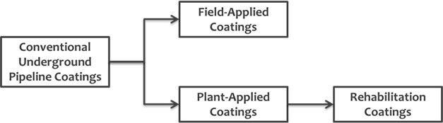
Coatings employed for internal and external protection are usually classified as organic and inorganic coatings. Each coating system has its own advantages and disadvantages where some of the coatings cannot be applied in the field due to environmental issues. NACE 0169 [1] classified the generic external coatings based on the substrate type, whether the coating will be applied on carbon steel or cast-iron material, Table 1 summarizes the coating classifications in detail. The published literature by different researchers classifies the external underground pipeline coatings as field or plant-applied coatings. Fig. 1 shows a schematic representation of external underground pipeline coating types. Table 2 shows the advantages and disadvantages of different coatings that could be used in the underground pipelines for rehabilitation, repair and field joints [2, 3]. Mamish et al. [4] described the pipeline coatings as main line and girth weld coatings. The main line coatings include cold applied tapes, fused tapes, Fusion Bonded Epoxy (FBE), two part Urethane and 2 and 3 layer polyethylene while girth weld includes: Shrink Sleeves, Cold Applied tapes and 2 part liquid epoxy.
Table 1Generic external coating systems applied on underground pipelines [1]
Underground and submerged pipe material | ||
Carbon steel pipe | Ductile iron pipe | |
External coating type | Asphalt/Coal tar enamel + concrete | Adhesive tape |
Coal tar enamel | Extruded polyethylene | |
Cold-applied and hot-applied tape | Reinforced cement mortar | |
Concrete | Field joint coatings | |
Elastomeric materials (Polychloroprene or equivalent) | Mastic coatings | |
Field-applied coatings for repair and rehabilitation | Polyurethane | |
Field joint coatings | Polyethylene sleeving | |
Fusion-bonded epoxy | Wax | |
Fusion-bonded epoxy + concrete | Zinc coatings | |
Liquid epoxy | ||
Mastic coatings | ||
Multilayer epoxy polyethylene | ||
Multilayer (including FBE primer) Polyethylene (PE) & Polypropylene (PP) Anticorrosion | ||
Polyolefin coatings | ||
Polyurethane | ||
Prefabricated films | ||
Wax |
Fig. 1Schematic representation of Underground Pipeline External Coatings
Singh et al. [5] compared in detail the performance of FBE multilayer coating with those of powder coating and reported improved performance of the FBE coatings. The multilayer coating system is a combination of polar structure FBE which is responsible for good adhesion to steel substrate and cathodic disbondment CD resistance and non-polar structure polyolefin, responsible for low water absorption and good insulation properties. Such a multilayer combination will definitely enhance the properties of the FBE coating; however one serious drawback of such system is its poor application problem, However, high performance composite coating (HPCC) could use to overcome the mentioned problem, HPCC is a powder multilayer coating contains FBE primer, medium density PE outer layer and PE adhesive outer layer. There are serious challenge considering the application of both of the above discussed coating systems on-site, because they require pipe preheating and cooling after application and prolonged curing time. After the coating system installation, some prior testes need to be carried out to ensure the best performance, which include adhesion, CD, flexibility, impact resistance, interface contamination and delamination etc.
Table 2Underground pipeline external coatings types based on application
Coating type | Coatings name | Comments | References |
Plant-applied | Fusion bonded epoxy (FBE), High density polyethylene (HDPE), Urethanes and etc. | [2] | |
FBE 3-layers (FBE+2-Polyolefine layers) Coal Tar enamel | FBE has no shielding Health concern to stop coal enamel | [3] | |
Field-applied | Spray Coating (epoxy, urethane, Zn…etc.), residues of refinery (waxes, petrolatum), bitumen based coating and single or multi-layer Polyethylene (PE)/butyl tapes | [2] | |
FBE Tape coatings Geotextile (mesh) backed tapes Two part epoxies Shrink Sleeves Coal tar, urethanes and liquid coatings | FBE can be applied in girth welds only Polyolefin or polyvinyl chloride (PVC) with a bituminous or butyl compound and Shrink sleeves causing (CP shielding) No shielding in mesh tapes | [3] |
3. Underground pipelines rehabilitation coatings
Rehabilitation coatings are considered as a radical solution for existing aged underground pipelines in order to eliminate the expected failure due to degradation of old assets and to increase the life of underground pipeline.
3.1. Types of underground pipelines rehabilitation coating types
There is no clear classification of rehabilitation coatings in the literature, however coatings classified by NACE as field-Applied Bonded Tape Coatings, these coatings can be used as repair or rehabilitation coatings as single or multi-layers. Fig. 2 shows a schematic representation of Bonded Tapes as per NACE 0109 [6]. Tables 3 and 4 show the advantages and disadvantages of different coatings that could be used in the underground pipelines as rehabilitation, repair and field joints respectively [7-10].
Fig. 2Classification of bonded tape coatings as per NACE
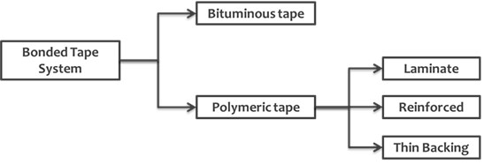
Table 3Advantages and disadvantages of different rehabilitation coatings
Rehabilitation coating type | Advantages | Disadvantages | Ref. |
100 % Solid liquid urethane | Flexibility Single coat Fast curing High abrasion CD resistance at <50 °C Tensile adhesion | Moisture sensitive Poor CD resistance at >50 °C Poor hot water adhesion Poor impact resistance at subzero temp. | [8] |
100 % Solid epoxy/ urethane | CD resistance at <80 °C Improved tensile adhesion Improve hot water adhesion | Slower curing than urethane Curing stops at 50 °C | [8] |
100 % Solid epoxy coatings | Improved CD resistance up to 95 °C Improved tensile and hot water adhesion Sag resistance | Slower curing than urethane Curing stops at 50 °C Increase temperature formulations | [8] |
High temperature epoxy | Cathodic disbonding (CD) resistance at 150 °C | [8] | |
Low temperature epoxy | cure at 0 °C | [8] | |
Damp surface epoxy: | CD resistance at 80 °C | [8] | |
Coal Tar and bitumen based coatings: | Adhesion loss when aged Causing CP current demands increase | [9] | |
Two-ply Tape system (PVC and PE tapes): | Removal of Plasticizers leading to adhesion loss | [9] | |
Self-amalgamating three-ply Tapes | Stabilizers to avoid spiral corrosion | [9] | |
Tapes | Surface tolerant Easy application | Sensitive to surface preparation Poor adhesion at overlap Not suitable (50-60 °C) Low resistance to soil stress | [10] |
Table 4Underground coatings advantages and disadvantages for field joints
Coating type | Advantages | Disadvantages |
FBE | Formation of magnetite layer Compatible with CP | Sensitive to SP |
HSS | Fast application Design temperature up to 100 °C | |
Polyurethane | Durable and corrosion resistance | High cost Limited to bends and field joints. |
Flame sprayed PE | Ease of use Compatible with main pipelines coating. | |
Cold wrapped tape | Low cost Easy application | Low resistance to soil stress Thermal ageing Poor adhesion |
The use of non-crystalline low viscosity coatings as rehabilitation coatings not only for the main pipelines but also girth weld is increasing due to its ease of applications and competitive price. The low viscosity coatings consist of a polar not cross-linked polyolefin. These coatings act as a fluid with wetting capability for adhesion improvements purposes. Since there will be only cohesive failure, so this fluid/coating can easily heal the irregularities in the substrate. These non-crystalline/amorphous materials (no reaction) to prevent the pressure build up within the coatings. It is also reported that such coatings can prevent MIC occurrence due to the presence of organic polymeric with inorganic filler (No nitrogen) [2]. Polymeric or viscoelastic coatings consist of poly-isobutene (covalent bonds contains hydrogen and carbon).
Such coatings considered having cold flow and non-cross linking properties. These coatings require 50 % overlap to strengthen the edges of the materials. It is reported that such coatings undergo any chemical reaction to achieve the adhesion, as it adhered very well on the substrate after application [11]. In one of studies carried by Richard et al. [12], they discussed coating systems consisting of a liquid adhesive covered by a spiral wrapping with geo-textile fabric backed rubberized bituminous compound and non-shielding outer wrap. This system uses primer to fill the surface irregularities and react with bituminous to enhance the adhesion properties. They just reported less than 10 failures for this product and those too were reported to be dur to inadequate application. They found water underneath the coating system with a pH value of 10 and that shows the effectiveness of CP system (no corrosion). Richard et al. [12] also compared the performance of this coating with solid film backings SFB (Shrink sleeves and tapes). The SFB is reported to have high dielectric strength they will lead to shielding of CP current and the other problem related to SFB is wrinkling due to soil stress specially in case of improper application. Roland et al. [13] reported issues of tape systems such as poor adhesion at overlap especially a butyl rubber, poor resistance to soil stresses and such systems are not suitable to be used in temperature range (50-60 °C) respectively.
3.1.1. Polymeric coatings process
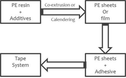
Polymeric tapes can be classified as cold or hot applied tapes respectively, Cold applied tapes are a blend of butyl rubber and synthetic resin in the form of tape to ensure good adhesion between inner layers and pipe. It is covered with high density polyethylene or polypropylene as outer layer to improve the strength and mechanical protection. Figs. 3 and 4 show the application and manufacturing process of cold applied tapes respectively. Hot applied tapes consist of thermally adhesive primer layer, thermoplastic elastomers adhesive layer and thermoplastic outer layer [12].
Fig. 3Schematic representation of underground rehabilitation coating applied on steel pipeline
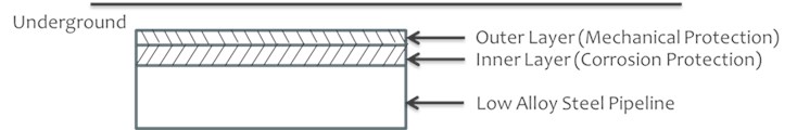
Fig. 4Manufacturing process of cold applied tape
Visco-elastic coating (STOPAQ CZ) Wrapping band system with 3 mm thickness was studied, both in laboratory and field conditions. Holiday detection, Impact resistance, Chemical resistance, EIS, and Cathodic Disbonding tests were carried out and compared with the field trail. It was noted that no holidays were found. The Impact test results were approved the self recovering of this type of coating. This type of coating was chemically stable, and the solution was not affected, or color changed. EIS, the impedance also shows good value without artificial defects but after the defects it becomes low. The results of CD tests confirmed the good behavior of this coating as no visible damage was detected. The maximum operating temperature for this product was 70 °C. During the field tests the pipeline was monitored every 12 months for a total of 4 years of exposure and window test was carried out but visually no visible damage or corrosion was found, and these results were in agreement with those observed in the laboratory tests [14].
4. Underground pipelines coating failure
The coatings considered failed when there is a blister or disbonded area and the corrosion under film is present [13]. Coating failures may be caused due to different factors such as wrong coating selection, soil condition and/or poor coating application. Therefore, the corrosion can proceed in the presence of moisture and salts and factors like; “poor adhesion between the coating and substrate, microbial activity, poor surface preparation and high permeability of the coatings” will aggravate the situation and ultimately failure will take place [1].
4.1. Coating failure
Permeability of the coating is the first stage of the failure, in another words when the coating has a pore, then these pores will be a gate for the air entrance causing disbonding phenomena. However, water also can penetrate through these pores to substrate completing the corrosion circuits and subsequently the coating can loss its adhesion in this manner [15, 16]. However, the causes of the coating failure can be summarized as:
1) Wrong coating selection.
2) Improper surface preparation.
3) Air and water permeation.
4) Loss of adhesion and cohesion.
5) Blisters.
6) Coating shielding.
7) Bacteria.
Baker et al. [17], reported a detailed survey of underground pipelines exists in the Gulf region buried in dry and wet soil conditions. It is reported in the literature that FBE coating system performance was excellent in dry conditions after 22 years of exposure except few minor defects and holidays were found in the weld seam. However, in wet soil conditions (Subkah area) there was disbonded area and blisters in single FBE coated pipelines after only 5 years in service. Roche et al. [18] reported two failure cases, i.e. in one case blistering of FBE coated pipeline was found after 10 years in service. The two key reasons reported for this failure were decrease in mechanical properties and ionic mobility at 80°C and secondly the improper working of CP system, as CP current was not able to reach and protect the substrate at low temperature. The second failure case was in 3LPE and HSS coated pipeline after 16 years of service and the failure was in the form of disbonding of HSS. This failure is reported to be mainly caused by thermal aging in the presence of water and oxygen and also due to poor surface preparation, which was conducted using brush.
4.2. Cathodic disbonding (state of the art)
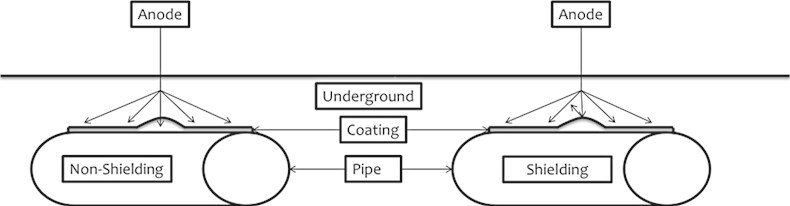
For rehabilitation coatings, the most critical property of the system is cathodic disbonding resistance where highly isolative coating may shield the cathodic protection current. This will increase the CP current demand and can no longer work economically. It has been reported that the new coated pipelines will need 10 µA/m2 and after deterioration of the coating the current of CP may reach 3500 µA/m2 to protect the aged pipe because the penetration of CP current will depend on many factors including coating type and thickness, electrical resistivity of the coatings, trapped water between coating and substrate and coating indentation by rocks (shielding) [19, 20, 21]. The decision of recoating old pipeline was made based on CP current demand which was significantly increased in 2007, the old coating system was an asphalt enamel coating installed in 1963, the new system is two parts, 100 % solid epoxy-urethane coating (0.5-0.75 mm thickness) [22]. Fig. 5 shows the difference between shielding and non-shielding coating.
The suggested mechanism of CD is the high alkalinity (high pH) of the water underneath the coating according to [11] the following reactions are present in the disbonded area:
O2 + 2H2O + 4e- → 4OH-
2H2O + 2e- → H2 + 2OH-
Based on the above equations the pH will increase significantly which may lead to disbonding of the coating layer, depending on several factors that are controlling the rate of the CD e.g. electrolyte nature, potential, DFT, time, surface preparation and presence of hypochlorite.
Fig. 5Schematic representation of the difference between shielding and non-shielding coatings
Rischard et al. [23] classified the SCC of underground pipelines as a high pH SCC and near natural pH SCC, High pH SCC can happen when the electrolyte penetrates through the coating then the corrosion underneath and that will ultimately result in crack initiation and propagation until coating failure.
Near pH SCC happens due to inadequate CP system of shielding coating in presence of CO2 from ground water. SCC failures could be avoided by well adhered coating system. Riscard et al. presented one case study in which failure of the field applied coating occurred within 5-10 years, without any issues of CP system, as it was working properly. The failed coatings were reported to be SS, SFB tapes and high dielectric strength SF backings while on the other hand FBE, mesh backed tape system, 2-part epoxy are allowing water to penetrate into the substrate without any evidence of corrosion or failure due to its compatibility with CP system. Coal tar and asphalt are become brittle with time leads to disbonded area then SCC may consider a major failure. SFB is easily stretch during application which will give chance to stretch later with time due to soil stress so water and other aggressive species will ingress through the coatings leads to wrinkles. SS is made of a high dielectric strength solid film polyolefin backing which will shield CP current easily so this product restricted to due to application sophistications. Mesh backed tape coating system could be used to overcome the mentioned issue regarding CP compatibility, 23 years of experience approved that no shielding and no corrosion or SCC was observed relevant to this product. The recorded failure related to FBE was not due to shielding but inadequate CP or no CP system at all. 3LPE or 3LPP and viscoelastic are susceptible to shielding due to thicker layer of polyolefin (high dielectric strength). Tow part epoxy are used in last 10 years in rehabilitation projects with no evidence of shielding. Wax and petroleum can also shield CP due to soil stress or mechanical damage.
Markus et al. [24] discussed another mechanism of CD taking into account presence of chloride so in addition to above cathodic reaction, the anodic reaction of chloride is: 2Cl- → Cl2 + 2e-.
As a result of the above anodic and cathodic reactions the delamination of the coating is highly expected, single layer of FBE (300-400 µm thickness) was tested in 3 % NaCl with hole defect 6 mm and 3 layer HDPE (7 mm thickness) tested in soil simulating solution with the same mentioned defect, the tests were conducted in order to see the probability of the delamination so the high thickness coating 3L HDPE was show lower delamination radius than FBE coating.
5. Rehabilitation coating selection criteria
The selection of the suitable coatings system is the most critical step in rehabilitation projects for underground pipelines to achieve the desirable characteristics of corrosion and mechanical resistance. Before proceeding to rehabilitation projects, some factors need to be studied and they include ''the distance and the location of the area need to be recoat, the weather in the area need to be recoat, type of coatings that can be used in such environments and the cost of rehabilitation project. the main coating selection factors are substrate lifetime and location, environments and soil conditions, Substrate material shape, coating manufacturer and capital and repair cost [1, 25]. The many reported failures are due to shielding problem in the oldest tape wrap system because they are used in conjunction with CP. As per the pre-requirements of the coatings, they must be environmentally friendly, safety, durable, corrosion and mechanical resistance, low cost, electrical insulator, moisture barrier, applied in the field, resist holidays, excellent adhesion, resistance to disbonding, bacteria and soil stress resistance in addition to that nontoxic [26, 27].
It is important to remember that corrosion prevention is not a simple task and involves a combination of design, implementation of the design through well written specifications, inspection and construction practices. In addition, if we are talking about underground corrosion protection we should define the critical environmental conditions when selecting the suitable coating because each coating system has its advantages and disadvantages.
According to NACE SP0109, the desirable characteristics of external coating adopted for underground pipelines are as follow: Effective electrical insulator; Effective moisture barrier; Application to pipe by a method that does not adversely affect the properties of the pipe; Application to pipe with a minimum of defects; Good Adhesion to pipe surface; Resistance to development of holidays with time; Resistance to damage during handling, storage and installation; Ability to maintain substantially constant electrical resistivity with time; Resistance to cathodic disbondment and disbonding from other factors such as soil stress; Resistance to chemical and thermal degradation; Ease of repair; Retention of physical characteristics; Nontoxic to the environment; Resistance to changes and deterioration during aboveground storage and long-distance transportation; Resistance to abrasion and mechanical stress; Compatible with cathodic protection; Resistance to microorganisms [10].
6. Performance evaluation comparison of different rehabilitation coatings
Nowadays Visco-elastic coatings or polymeric coatings are the best choices for the rehabilitation projects due to ease of application (no extensive preparation needed) and competitive prices, however comprehensive tests need to be developed and selected to figure out the wrinkling, sagging and shielding problems related to this type of coatings. Doddema et al. [28] has reported new coating system that for rehabilitation purposes to meet the current requirements, it is fully amorphous and is not cross linked, it is an inert means no reaction to this coating materials and it has self-healing properties. It doesn’t require extensive surface preparation [29]. In another study carried by Richard et al. [30], two most common problems related to tapes coating (solid film backing and Shrink sleeves etc.) were mentioned to be soil stress and CP shielding. Therefore, another product with a woven geotextile fabric backing system has been developed to overcome the problems of solid film backing systems, the elongation of the geotextile system was found to be 12-24 % while it was reaching about 641 % for solid backed system indicating the susceptibility to wrinkling and disbonding [30], “polymeric tapes are rarely used due to cathodic shielding problems but it can be used as repair or in the joints” [31].
Different tests were conducted on RD-6 Polyguard in accordance with ISO /FDIS 21809-3:2008 (E), Table 5 summarizes these results. It is clear from these results, that the tests results were within standard recommendations except the specific electrical resistance, which was lower than the recommended value by ISO, However, from CD test, we can observe that this product is compatible with CP system [32].
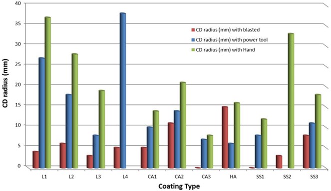
Eleven coating systems were subjected to tests which include 4 liquid coatings (L1-L4), 3 cold applied tapes (CA1-CA3), 1 hot applied tape (HA) and 3 shrink sleeves (SS1-SS3), the application was made in order to simulate the field conditions so the requirements of the pipe preheating in shrink sleeves, restricts the use of this coatings in the rehabilitation projects. The main obstacle of the liquid coatings was the time before backfilling. Hot applied tape was easier than shrink sleeves which require more skill labor in the application. The cold applied one was the faster and easier coatings. The main tests include CD, impact resistance, adhesive failure, and soil stress, which were conducted on the above-mentioned systems at different temperature. Fig. 6 shows the results of the CD tests, and it is to be noted that application methods play an important role in CD radius which affect the values significantly [33].
Table 5Results of different tests carried on RD-6 Polyguard
Test name | Criteria | Result | Standard recommendation |
Holiday detection | 4000-8000 volts | No holidays | No holidays |
Impact resistance | @20 ±5°C | Average of 6.8 J/mm | ≥ 4 J/mm |
Specific resistance | 0.1M NaCl for 100 days | ˂ 108 Ω | Rs100 ≥ 108 Ω |
CD | Room temperature & 50°C, 3% NaCl for 28 days, –500 mV was applied | 0 mm delamination radius | |
Peel strength | Hot water soak @50°C for 28 days | 3.4 N/mm unexposed 4.7 N/mm exposed to HWS | ≥ 1 N/mm for unexposed ≥ 0.4 N/mm for HWS |
Fig. 6CD tests carried on different coating types
Modified CD test was conducted on different coating types; these include (Asphalt, epoxy, tapes, urethane, multi-layer, FBE) at fluctuating temperature as well as 65 C were used, the current demand was monitored after each 4 hrs., A soil simulating solution NS4 was used for 14 months duration and potential was kept (–0.78 - –0.93 V vs. SCE). Table 6 shows that tapes are the easiest coatings in the application and no extensive surface preparation is required, however the main drawback is wrinkling and shielding [34].
Table 6Results of modified CD test conducted on different coating types
Coating Type | Surface Preparation requirements | Application temperature (°C) | Physical Observation | |
Constant Temp. | Fluctuating Temp. | |||
Asphalt | NA | Service Coating | Disbondment | Disbondment |
Coal tar A | SSPC-SP6 | 245-275 | Disbondment | Blistering & Disbondment |
Coal tar B | SSPC-SP6 | 245-275 | Disbondment | Blistering & Disbondment |
Tape | No requirements | 25 | Wrinkling | Wrinkling |
FBE A | SSPC-SP10 | 250 | Blistering & Disbondment | Blistering |
FBE B | SSPC-SP10 | 250 | Blistering & Disbondment | Blistering & Disbondment |
Epoxy Spray | SSPC-SP10 | 10-100 | Blistering | Blistering & Discoloration |
Epoxy Brush | SSPC-SP10 | 10-100 | Blistering | Discoloration |
3-Layer | SSPC-SP10 | 250 | No Change | No Change & Discoloration @0.93 V |
Urethane Spray | SSPC-SP10 | 10-100 | Blistering | Discoloration |
Urethane Brush | SSPC-SP10 | 10-100 | Blistering | No Change |
2-Layer | SSPC-SP6 | 50-60 | Slippage & Disbondment | Slippage & Disbondment |
Composite | SSPC-SP10 | 250 | No Change & Disbondment @–0.93 V | No Change & Discoloration |
Three coatings (3-Layer PE, HSS and fiber backed tapes) were tested for water absorption and electrical resistance and results were compared with FBE. The stability of the water was achieved in 24 hours in PE and HSS while it took around 28 and 20 days for tapes and FBE respectively. Fig. 7 shows the results as it is clear that all the tested coatings were having high resistance ≥ 1014 Ω.cm while FBE has 109 Ω.cm considered semi-conductor. The advantages of FBE are low cost and its CP compatibility. The coating system, 3LPO suitable when CP cannot be inspected periodically in a proper way due to limitations such as “high thickness”. The water permeability will be reduced, and hence proper insulation is achieved and so the results will be good adhesion as well as mechanical resistance [35].
Two fields coatings: 3 layers (FBE with 0.15 mm – ethylene vinyl acetate (EVA) with 0.175 mm – HDPE with 1.25 mm), and 2 layers (EVA with 0.175mm – Polyvinylidene Chloride (PVDC) with 1.25 mm) were tested in order to investigate the ingress of H2O, O2 and CO2 at room temperature. The evaluations were made based on Fick’s law measuring the permeability of the coating to the above species. PVDC was better among all layers for all species while FBE was impermeable to H2O, O2 and HDPE was better to H2O [36].
Fig. 7Electrical resistance and water absorption results
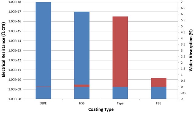
Table 7Tests Screen conducted on different underground pipeline coatings
Test type | Standard used | Parameters | Medium and duration | Aim of the test |
CD | ASTM G-8 ASTM G-42 | 25 °C 95 °C –1.5 V vs.SCE | 3% NaCl 30 days | Compatibility with CP |
Peeling | DIN 30670 | Intrinsic characteristic | ||
Adhesion | ASTM D-3359 ASTM D-4541 | |||
Impact resistance | ASTM G-14 | Mechanical damage | ||
Water absorption | 25, 60, 90 °C | 48 hrs | Permeability of the coatings | |
Hot water immersion | 50, 95 °C | 48 hrs | Permeability with ageing | |
Soil stress | 3 years |
Table 8Ranking of different coating types
Type of test | Coating type | ||||||||
FBE | Tape | Multilayer | Coal tar | Urethane | PE | Cementitious | Concrete epoxy on FBE | Wax | |
CD | Low | Medium-high | Low | Medium | High | Acceptable | Moderate | Very low | Acceptable |
Adhesion | Excellent | Moderate | High | Good | Low | Good | Good | Excellent | Low |
Impact resistance | Low | High | High | Very low | High | Good | High | High | Very low |
Water absorption | Moderate | Low | Low | Low | Low | Low | High | High | Very low |
Soil stress | Low resistance | ||||||||
Different types of coatings were subjected to evaluate the soil stress resistance, and the tapes system was found to be the most susceptible type to wrinkling phenomena [37]. Valmere at el. [38] evaluated different coating types that can be used in new or old underground pipelines. Tables 7 and 8 summarizes their evaluation in detail (tests conducted, aim of the test and results obtained) and it was suggested to use tapes in environments where soil stress is not a major consideration. Another limitation of the tapes was the temperature, and it was reported not to use them at temperature above 60 °C. The best performance was obtained through multilayer system, but its the only drawback was cost and application challenges [38].
7. Conclusions
Nowadays end-user is looking for suitable coating systems, that can resist attended conditions to avoid the risk of failure incidents and any production loss. Prior to change the existing coating system, a detailed evaluation scenario is required to study the status of currently used coating whether it is economical to replaced them or not. In any rehabilitation or recoating projects comprehensive laboratory experiments as well as field tests need to be conducted in accordance with available standards and methods in order to evaluate different candidates’ coating systems, by considering application and installation costs.
Recently, Polymeric tapes are emerging as promising systems in rehabilitation or repair projects due to ease of application, no extensive surface preparation requirements and they can be applied when the pipeline in service conditions. However, there is not much published data (lab as well field) regarding the performance and challenges related to these coatings, so therefore, new techniques are required to examine the winkling, sagging and cathodic disbonding issues related to tapes systems.
References
-
“Control of External Corrosion on Underground or Submersed Metallic Piping Systems, SP0169-2013, Item No. 21001,” Nace Standard.
-
Jf. Doddema, “The uses of self-healing visco-elastic coatings on underground pipelines,” World Pipelines, Oct. 2007.
-
R. Norsworthy, “Understanding corrosion in underground pipelines: basic principles,” in Underground Pipeline Corrosion, Elsevier, 2014, pp. 3–34, https://doi.org/10.1533/9780857099266.1.3
-
Abboud L. Mamish, “Tape coating system for pipeline corrosion protection system,” in Presusure Sensitive Tape Council, 2018.
-
P. Singh and J. Cox, “Development of a cost effective powder coated multi-component coating for underground pipelines,” in Corrosion, 2000.
-
Nace Standard Sp0109, “Field Application of Bonded Tape Coatings for External Repair, Rehabilitation, and Weld Joints on Buried Metal Pipelines,” NACE International, Item No. 21143, 2009.
-
Ali N. Moosavi, “Advances in field joints coatings for underground pipelines,” in Corrosion, 2000.
-
Chris Alliston, Banach, and Joe Dzatko Liquid Skin, “The development of liquid epoxy coatings for extending the life of existing pipelines,” World Pipelines, Nov. 2002.
-
Michael Schad, “Rehabilitation of corrosion protective coatings on buried steel pipelines,” Technical Report, Corrosion Protection, 2012.
-
Richard Norsworthy, “Coatings used in conjuction with cathodic protection – Shielding vs non-shielding pipeline coatings,” in Corrosion, Jan. 2009.
-
Dennis Neal, “Pipelines coatings failure – not only what you think it is,” in Corrosion, 2000.
-
Richard Norsworthy and Chic Hughes, “Proven protection,” World Pipelines, Coatings and Linings, Nov. 2007.
-
Roland Palmer-Jones, Phil Hopkins, and David Eyre, “Pipeline rehabilitation planning,” Rio Pipelines, Technical Paper, 2005.
-
Moufaq I. Jafara, Fikry F. Barouky, and Khalid Al-Mugary, “Evaluation of Visco-elastic Coatings – A User Perspective,” Saudi Aramco, Technical Report.
-
O. Knudsen and J. I. Skar, “Cathodic disbonding of epoxy coatings – effect of test parameters,” in Corrosion, Mar. 2008.
-
Sankara Paravinasam, Micheal Attard, and R. Winston Revie, “External polymeric pipeline coating failure modes,” Material Performance, Oct. 2006.
-
Baker S. Hammed, “Performance of desert pipelines and options for rehabilitation,” JPCL, Technical Report, Dec. 2013.
-
M. Roche, “External corrosion of pipelines: What risk?,” in SPE Middle East Oil and Gas Show and Conference, Mar. 2005, https://doi.org/10.2118/93600-ms
-
J. Alan Kehr, “Rehabilitation of pipeline coatings can reduce cost and risk,” in Corrosion, 2003.
-
X. Compaignalle, M. Meyer, F. Bernard, and S. Karcher Ans S. Gastaud, “Organic coatings aging consequences on under CP buired pipelines corrosion protection-simulated defects-,” in Corrosion, 2004.
-
R. Norsworthy, “Causes of external corrosion on coated and cathodically protected pipelines,” in Corrosion, Mar. 2009.
-
J. Diddas, “Recoating and coating rehabilitation extend the service life of petroleum pipelines,” Material Performance, May 2010.
-
Rischard Norsworthy, Matthies Jurgk, Carsten Heinks, and Jorg Grillenbager, “Importance of locating disbonding coatings with electo-magnitic transducer technology,” in Corrosion, 2012.
-
Markus Betz, Peter-Josef Gransfeld, and Ulrich Smit, “Cathodic disbonding test: what are we testing?,” in Corrosion, 2012.
-
C. R. Reeves, “Pipeline rehabilitation: using field applied tape systems,” in Corrosion, Mar. 1998.
-
Michael Romano, Matt Dabiri, and Alan Kehr, Protecting and Maintaining Transmission Pipeline. A JPCL eBook, 2012.
-
Shiwei William Guan, W. Pipe, Shiwei William Guan, “Corrosion protection by coatings for water and wastewater pipelines,” Technical Report, 2001.
-
J. F. Doddema and H. Vugtereen, “New pipeline coatings system-putting an end to coatings degradation,” in 7th Pipeline Technology Conference, 2012.
-
J. Doddema, “The use of visco-elastic self-healing pipeline coating,” in Corrosion, Mar. 2010.
-
R. Norsworthy, “Addressing soil stress and CP shielding by using a woven geotextile fabric backed tape system with a rubber modified bituminous compound,” in Corrosion, Mar. 2000.
-
Kenneth B. Tator, “Laboratory testing of pipeline exterior coatings-a commentary on correlation with field performance,” Corrosion, 2006.
-
Polyguard Tests
-
“Field Applied Pipeline Coatings,” Charter Coatings Service Ltd, Joint Inductry Project.
-
Sankara Paravinasam, Micheal Attard, and R. Winston Revie, “Modified cathodic disbonding testing of external polymeric coatings,” in Corrosion, 2007.
-
Robert Buchanan, “A critical review of inductry codes and standards as they relate to electrically resistive coatings and what that means to sheilding,” in Corrosion, 2013.
-
F. M. Song, D. W. Kirk, D. E. Cermeck, and D. Wong, “Barrier properties of two field pipeline coatings,” Material Performance, Vol. 44, No. 4, pp. 26–29, Apr. 2005.
-
A. Andrenacci and D. T. Wong, “Simulation of coating behavior in buried service environment,” in Corrosion, Jan. 2007.
-
Valmere Rodriguez, Elias Perozo, Lino Castareda, and Elena Alvarez, “Laboratory coatings evaluations and its relationship with the selection to protect pipelines against external corrosion,” in Corrosion, 1998.
About this article

