Abstract
The issue of utilization of excess energy of throttled natural gas is still relevant today. To solve it, various devices are used, based on such principles as on the Ranque-Hilsch vortex effect, temperature stratification using the Leontief tube, expander-generator sets and devices based on the Hartmann-Sprenger effect. One of the most common devices at gas distribution stations (gas gate station) is the turboexpander. The principle of its operation is based on the expansion of the gas flow with the performance of external mechanical work. Taking into account the increased interest in hydrogen fuel in connection with the course announced by the UN for decarbonization of production by 2050, the modern gas transmission system can become a secondary source of electricity for hydrogen production, thereby solving the problem of excess pressure energy utilization at gas distribution stations. The technological solution for using this energy is the installation of turboexpanders and electrolysis of water at gate stations in order to produce hydrogen.
1. Introduction
Long distances of gas transportation cause high pumping pressure, which must be reduced to a predetermined value before being sent to the consumer. Gas reduction is the process of reducing the pressure at the gas distribution stations (GDS) or gate stations. It is carried out by spending the energy of the natural gas flow to overcome local resistance, which is a throttle body as part of the pressure regulator.
2. Gas reduction energy utilization methods
Under the conditions of gate stations, natural gas energy utilization during its reduction is carried out in the following ways: using a device based on the Ranque-Hilsch vortex effect, temperature stratification using the Leontief tube, expander-generator sets, devices based on the Hartmann-Sprenger effect.
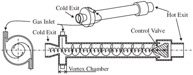
One of the most famous and widespread machineless method of energy separation of gas flows is the vortex method proposed by J. Rank in 1931. After studying the vortex effect by Robert Hilsch, the device was called the Rank-Hilsch tube or vortex tube. The effect is to separate a gas or liquid into a hot and cold stream when swirling in a cylindrical or conical chamber [1].
The operation of the device based on gas-dynamic temperature stratification (Leontiev tube) is based on the implementation of heat transfer between flows of different speeds (Mach number) separated by a wall. The basis of the process is the difference between the gas reduction temperature on the wall and the stagnation temperature [2].
The expander-generator set is a device in which the energy of the stream of transported natural gas is first converted into mechanical energy with a loss of pressure and temperature (Joule-Thompson effect) in an expander, and then into electrical energy in a generator.
In devices based on the Hartmann-Sprenger effect, breaks in the jet of a high-velocity gas flow at the entrance to a plugged cavity cause pressure pulsations. Pulsation waves propagate and are reflected from the dead end and move in the opposite direction, entering with subsequent waves into resonance with a sharp increase in temperature. As a result of energy loss, the gas stream enters the outlet of the installation cooled.
Fig. 1A schematic diagram of the Ranque-Hilsch Vortex Tube (Source: https://www.researchgate.net)
2.1. Turboexpander
From the point of view of energy saving in the gas transmission system, today it is very promising to utilize the energy of natural gas excess pressure in a turboexpander as one of the ways to use secondary energy resources. Thus, in 2019, PJSC Gazprom used 21 turboexpander units, and the total volume of electricity produced amounted to 74,679 kWh [3].
For the first time, the idea of using expander-generator units was considered and implemented in the method of obtaining liquid air by Academician P. L. Kapitsa. In 1947, engineers P. A. Sling, A. A. Degtyarev and G. M. Ryabinin and Professor M. D. Millionaires have been suggested to use DGA to take advantage of natural gas pressure drop. In 1948, this proposal was experimentally substantiated by A. V. Alexandrov. The experimental DGA installed at the hydraulic fracturing of the Dashava soot plant produced about 50 kW of electric power [4].
A turboexpander set is a device for generating electricity from the work done by expanding main natural gas (without burning it). It consists of a generator, expander, heat exchanger, automated control system, regulation and control of process parameters (Fig. 2) [5].
Fig. 2A schematic diagram of a turboexpander
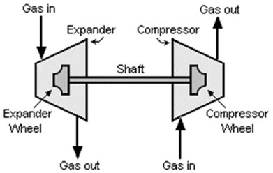
The gas or gas mixture passes through fixed guide channels (nozzles), which convert part of the potential energy of the gas into kinetic energy, and through a system of rotating blade channels of the shaft. With a sharp expansion of the gas, a pressure drop occurs, and when it performs the mechanical work of rotating the shaft, intensive cooling of the gas occurs. Together with the shaft, the compressor (generator) impeller mounted on it rotates. The turboexpander unit is sealed and does not consume electricity.
Conversion of the energy of the transported compressed gas into the energy of the flow and its subsequent use in order to obtain external work can be done in different ways. If, first, with the help of a fixed nozzle apparatus, the gas is completely expanded, and then this flow, which moves at high speed, is directed onto the blades in order to make the blade disk rotate, then such a turboexpander is called active. If, without preliminary expansion in the nozzle apparatus, the gas flow is directed directly into the interblade space of the impeller for full expansion, then such a turboexpander is called jet. However, a combination of these two stages is considered economically feasible. In the impeller of the turboexpander, as well as in the nozzle apparatus, the direction of gas movement is radial, axial or radial-axial.
The classification of existing turboexpanders is presented in the Table 1.
Table 1Turboexpander types
Parameter | Type |
Direction of gas flow | Centrifugal |
Centripetal | |
Axial (radial) | |
Degree of gas expansion in the nozzles | Active (pressure reduction occurs only in fixed guide channels) |
Reactive (pressure also decreases in the rotating channels of the rotor) | |
Number of steps | Single stage |
Multistage |
3. Hydrogen generation
Due to the depletion of the world's reserves of non-renewable energy sources, in recent decades, the governments of many countries around the world have been focusing on the research and implementation of renewable energy sources in all areas of production and everyday life. According to the Technical Report provided by the International Energy Agency in 2019, the demand for hydrogen fuel has tripled since 1975 [6].
Currently, about 90-95 % of hydrogen is obtained by steam reforming, which results in carbon dioxide emissions into the atmosphere in the amount of 830 million tons per year. One of the most environmentally friendly and promising methods is water electrolysis, which produces no more than 0.1 % of hydrogen in the world [6]. An important factor in the growing popularity of this method is the reduction in electricity prices in the EU and Japan due to its generation from renewable energy sources (solar and wind energy).
When turboexpanders are installed at gas distribution stations, the discharge energy is converted into electrical energy. The generated electricity is surplus and is mainly used for the needs of the GDS itself. By generating hydrogen at the GDS, the Gas Transportation System, in turn, will solve the problem of utilizing this energy.
Taking into account these facts, the technological solution for using the electric power generated by the turbo expander is to carry out water electrolysis at the GDS. Hydrogen production requires a voltage called thermoneutral voltage. Its value is 1.48 V. The process of water decomposition in this case at 25 °C will occur without heat supply from outside. At this voltage, 3.54 kWh is consumed per 1 m3 of hydrogen [7]. Thus, the turboexpanders installed at PJSC Gazprom can produce 21,095 m3 of hydrogen per year.
In the process of electrolysis of water, oxygen will be released at the anode, and hydrogen will be released at the cathode in a volume ratio of 1:2. To obtain 1 m3 of hydrogen and 0.5 1 m3 of oxygen under normal conditions, it is theoretically necessary to consume 805 g of water. Practically, water demand is 820…850 g [7]. Then the required amount of water at maximum water consumption is 17,931,000 g or 17.9 m3 at a water density of 1000 kg/m3.
The source of water, in turn, at each individual GDS can be the nearest underground or surface watercourse.
4. Methane-hydrogen mixture
Hydrogen does not require the creation of its own transport system; for these purposes, a natural gas transportation system can be used by mixing a certain proportion of hydrogen into the gas. For many countries in Europe and the US, this technology will not be an innovation. In cities from the 19th to the mid-20th century, there were gas supply systems with “town gas” (town gas), obtained artificially from coal. The hydrogen content of such a gas was usually about 50 %. In different countries, different proportions of hydrogen mixing into natural gas are allowed, from 0.1 % (in Belgium, New Zealand, Great Britain and the USA) to 10 % in Germany and 12 % in the Netherlands. The upper limit is determined by national technology standards related to the safety of gas pipelines and gas flaring equipment. Research by the National Renewable Energy Laboratory shows that the 15% mark can be reached in existing gas transportation systems without any major changes, and in some cases, it can be seriously exceeded [8].
In order to identify the optimal concentration of hydrogen in the mixture, the Wobbe Index (WI) was calculated. WI or Wobbe number is an indicator of the interchangeability of fuel gases such as natural gas, liquefied petroleum gas (LPG) and town gas, and is often specified in gas supply and transmission specifications.
It is defined by Eq. (1) [9]:
where – volumetric net calorific value, MJ/m3; – gas density, kg/m3; – air density, kg/m3.
The Wobbe index is used to compare the combustion energy output of fuel gases of different composition in an appliance (fire, stove, etc.). If two fuels have the same Wobbe index, then for a given pressure and valve setting, the energy output will also be identical. Typically, deviations of up to 5 % are allowed, since they will not be noticeable to the consumer.
The Wobbe index is a critical factor in minimizing the transition impact when analyzing the use of natural gas substitute (SNG) fuels such as propane-air blends. The Wobbe index also requires the addition of propane to some enhanced biomethane products, especially in regions where natural gas has a high heating value, such as Sweden.
The Wobbe index for natural gas from the Urengoy field is WI = 49.066 MJ/m3. The allowable fluctuation of the Wobbe index is 5 % and equals 46.613 MJ/m3 for the lower allowable limit. The result of calculating the highest possible percentage of hydrogen impurity based on the Wobbe index is shown in Table 2 and is 23.76 % hydrogen in the mixture.
Table 2Calculation of the Wobbe number and the possible concentration of hydrogen in the mixture
Hydrogen concentration | Natural gas concentration | Lower calorific value of the mixture | Density conversion | Wobbe index |
Н2, % | NG, % | , kJ/m3 | , kg/m3 | WI, MJ/kg3 |
23.5 | 76.5 | 29,576 | 0.5200 | 46.639 |
23.6 | 76.4 | 29,551 | 0.5193 | 46.629 |
23.7 | 76,3 | 29,526 | 0.5186 | 46.619 |
23.72 | 76.28 | 29,521 | 0.5185 | 46.617 |
23.74 | 76.26 | 29,516 | 0.5184 | 46.615 |
23.76 | 76.24 | 29,511 | 0.5182 | 46.614 |
23.78 | 76.22 | 29,506 | 0.5181 | 46.612 |
23.8 | 76.2 | 29,500 | 0.5180 | 46.610 |
23.9 | 76.1 | 29,475 | 0.5173 | 46.600 |
24 | 76 | 29,450 | 0.5166 | 46.590 |
While useful, the Wobbe index by itself is not a complete indicator of the interchangeability of two or more gases or their mixtures. Other criteria must be taken into account when determining whether a fuel is sufficient to replace the fuel used to regulate the combustion system.
5. Conclusions
The production and use of hydrogen is one of the promising ways to reduce carbon dioxide emissions and can become an alternative to utilizing the energy of throttled gas at gas distribution stations. One of the ways to use the obtained hydrogen is to mix hydrogen with natural gas for supply to the gas distribution network. By calculating the Wobbe Index, it is possible to determine the optimal concentration of hydrogen in the mixture, but other parameters of the system should also be taken into account.
References
-
A. Schipachev and A. Dmitrieva, “Application of the resonant energy separation effect at natural gas reduction points in order to improve the energy efficiency of the gas distribution system,” Journal of Mining Institute, Vol. 248, pp. 253–259, May 2021, https://doi.org/10.31897/pmi.2021.2.9
-
A. Tsynaeva, E. Tsynaeva, and E. Shkolin, “Using heat pipes to improve the efficiency of gas-dynamic thermal stratification,” Vestnik of Samara University Aerospace and Mechanical Engineering, Vol. 43, No. 3, pp. 192–197, 2013.
-
“Use of Renewable and Secondary Energy Sources Environmental,” Report of PJSC Gazprom, 2019.
-
S. N. Yatrov, Energy Saving Technologies in the Ussr. Abroad. Analytical Album. Moscow: Firm “Energy Saving”, 1990.
-
V. S. Agababov, A. V. Koryagin, V. L. Titov, and Yu. Yu. Hamer, “The use of expander-generator units in industry,” in Engineering Ecology – XXI century, pp. 16–18.
-
“The Future of Hydrogen: Seizing today’s opportunities,” IEA, Technology report, 2019.
-
D. Yu. Hamburg, V. P. Semenov, N. F. Dubovkin, and L. N. Smirnova, Hydrogen. Properties, Receipt, Storage, Transportation, Application. Moscow: Khimia, 1989.
-
T. Mitrova, Yu. Melnikov, and D. Chugunov, Hydrogen Economy – the Path to Low-Carbon Development. Moscow: Moscow School of Management SKOLKOVO, 2019.
-
“Wobbe Index, Technical Library”, https://neftegaz.ru/tech-library/ngk/148130-vobbe-indeks-wobbe-index/
About this article

