Abstract
Simulative studies on a series of the cylinders subjected to underwater explosion were presented using coupled acoustic-structural analysis in ABAQUS in order to analyze the large local deformation feature and the influence of the outer water tank. The results revealed that large inward local deformation occurs on the front side of the cylinder, and the plastic hinge locates near the boundary of the spherical projection of the explosion to the cylinder with an approximate elliptic type. The inner water and the outer shell’s thickness of double-shell cylinders have great influence on the large local deformation feature of the inner shell, and with the increase of the outer shell’s thickness, large local inward deformation occurs on the back side of the cylinder, which is caused by the local jet effect of the inner water. The research can provide reference to the design and assessment of underwater anti-explosion structures.
1. Introduction
Cylinders are widely used in submarines, underwater vehicles and aerospace vehicles depending on their excellent structural strength. With the rapid development of underwater warfare equipment, the anti-explosion ability of submarines and underwater vehicles has been drawing more and more attentions. For the requirement of reserve buoyancy, inner and outer water tanks exist comprehensively in underwater equipment. Therefore, it is of great importance to research the large local deformation features of cylinders subjected to underwater explosion and the influence of water tanks outside them in order to increase their anti-explosion ability.
Focusing on the dynamic response of cylinders subjected to impulsive loading, many researches have been carried out in the past few years. Kirkpatrick and Holmes studied the failure behavior of aluminum cylinders subjected to lateral explosive loading [1]. Jones et al. carried out theoretical and experimental researches on the deformation feature of long tubes under lateral impact [2]. Wierzbicki and Hoo Fatt carried out studies on the damage assessment of cylinders subjected to impulsive loading [3]. Hu et al. researched the damage assessment problem of underwater targets subjected to underwater explosion [4]. Yao et al. studied the application of the acoustic-solid coupling algorithm in ABAQUS on simulative calculations of underwater explosion [5]. Shao studied the pressure field around the cylinder subjected to underwater explosion [6]. Gao et al. studied the dynamic buckling behavior of steel cylinders subjected to lateral air blast, and four typical types of buckling modes were obtained [7]. Yuan et al. studied the dynamic buckling of cylinders subjected to underwater explosion [8]. Ji et al. studied the local deformation of long steel cylinders subjected to lateral air blast using simulative and experimental methods, and found that the deformed section was as an elliptic type [9]. Zhang and Yao analyzed the dynamic coupling process of underwater explosion bubble with the cylinder using a three dimensional underwater bubble analyzing program, which matched well with the experimental results [10]. Liu et al. studied four damage modes of cylindrical structures impacted by underwater explosion using a bi-progressive method [11]. While former literatures have not studied the large local deformation features of cylinders subjected to underwater explosion, nor the influence of the jet effect of the inner water between the two shells of the cylinder.
In this paper, a series of simulative studies on the cylinders subjected to underwater explosion were presented using coupled acoustic-structural analysis in ABAQUS, and the different deformation features between the double-shell cylinder and the single-shell one were analyzed, as well as the reason to cause the difference and the influence of the outside water tank on it. The influence of the jet effect was studied by analyzing the velocity field of the inner water. From many conventional points of view, the outside water tanks of cylinders may provide good protection effect, while according to the analysis in this paper, the jet effect will probably cause unpredictable damage to cylinders in some certain conditions, which shall be paid enough attention and may provide reference to the subsequent further corresponding researches.
2. Simulative analysis models of single-shell and double-shell cylinders
The single-shell cylinder locates horizontally under the water surface by 2 m, with two ends sealed by two caps and fixed. The outer diameter of the cylinder is 196.0 mm, the length is 292.0 mm, and the thickness is 7.9 mm. The thickness of the two caps used to seal the cylinder is 12.0 mm. The length, inner diameter and inner thickness of the double-shell cylinder are the same as that of the single-shell one, as well as the thickness of the caps. The thickness of the outer shell is 3 mm, and the radial distance between the inner and outer shells is 40 mm. The space between the two shells is also filled with water. The mass of the explosive made by TNT is 0.22 Kg, which locates up the middle of the cylinder by 0.585 m. The cylinder and the caps are made by 304 stainless steel. The finite element models of the single-shell cylinders and the outer water were built with ABAQUS software, and the diameter of the outer water is 6 times as the cylinder.
The double-linear strengthening model was used to 304 stainless steel, with Young’s modulus to be 200 GPa, Poisson ratio to be 0.3, elastic limit to be 210 MPa, tangent modulus to be 2.4 GPa, and density to be 7800 Kg/m3.
The pressure of the underwater explosion will arrive the peak value very soon and then decay exponentially. Considering that the diameter-thickness ratios of the cylinders analyzed in this paper is relatively small (for the single-shell one about 12.4), and that the depth of the explosive is also small, so we assume that the large local deformation is mainly caused by the shock wave pressure, neglecting the influence of the bubble fluctuation. The pressure of the underwater explosion adopted Geers-Hunter’s semi-empirical formula [12] as follows:
where is the peak value, and is the time coefficient of attenuation.
3. Simulative results of the single-shell cylinder and analysis
The pressure of the underwater explosion was imposed to the connecting surface of the outer shell and the water as a discrete array. The cylinder and the caps adopted shell elements, while the outer water adopted solid elements. The simulative calculation was calculated using the acoustic-solid coupling algorithm in ABAQUS, and the whole calculation time was 20 ms. The nearest point on the cylinder to the explosive was marked as point A. The normal displacement response at point A is shown in Fig. 1 and the normal speed response at point A is shown in Fig. 2. The deformations and stress distributions of the cylinder at each instant are shown in Fig. 3.
With the impact of the underwater explosion, large inward local deformation occurred on the front side of the cylinder, and the largest value of the plastic deformation appeared at point A. Through the simulative calculation by ABAQUS. As is shown in Fig. 2, the deformation speed at point A firstly ascended, then descended and then ascended heavily for the second time. For this phenomenon, in the initial deformation stage, the rapid increase of the underwater explosion amplitude caused the increase of the deformation speed. While in the following deformation stage, the increase of the elastic deformation energy took negative influence on the increase of the deformation speed in a certain degree. And in the subsequent deformation stage, local dynamic buckling occurred in the cylinder and obvious plastic hinge appeared in the front side, which caused the heavy increase of the deformation speed with the decrease of the anti-deform ability.
Fig. 1Normal displacement response at point A
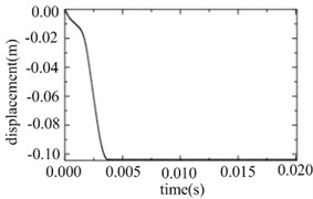
Fig. 2Normal speed response at point A
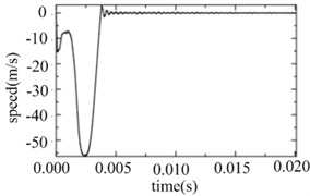
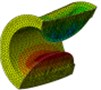
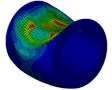
Fig. 3Deformations and stress distributions of the cylinder at each instant
a) Initial instant

b) Instant at 1 ms

c) Instant at 2 ms

d) Instant at 3ms

e) Instant at 4 ms

f) Instant at 20 ms
As is shown in Fig. 3, the plastic hinge located near the boundary of the spherical projection of the explosion to the cylinder with an approximate elliptic type. From the simulative results we can also find that obvious plastic deformation didn’t appear in the parts not covered by the spherical projection of the explosion to the cylinder.
4. Simulative results of the double-shell cylinder and analysis
4.1. Finite element simulation results basing on ABAQUS and analysis
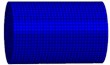
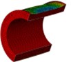
The caps and the two shells of the cylinder adopted shell elements, while the outside water and the inner water adopted solid elements. The general connecting model was adopted on the probable interfaces between the caps and the two shells of the cylinder. The simulative calculation was calculated using the acoustic-solid coupling algorithm in ABAQUS, and the whole calculation time was 20 ms. In order to be compared to the results of the single-shell cylinder, the nearest point on the inner shell of the double-shell cylinder to the explosive was marked as point A, while that on the outer shell was marked as point A’. The normal displacement response at point A and A’ is shown in Fig. 4, and the normal speed response is shown in Fig. 5. The deformations and stress distributions of the cylinder at each instant along - section are shown in Fig. 6, and the deformations and stress distributions of the cylinder at each instant along - section are shown in Fig. 7. The vertical velocity field of the inner water at each moment along - section is shown in Fig. 8.
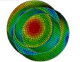
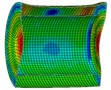
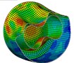
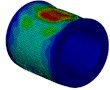
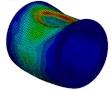
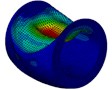
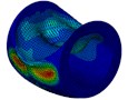
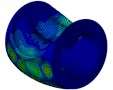
As is shown in Fig. 4-7, with the impact of the underwater explosion, large local plastic deformation firstly occurred on the front side of the outer shell of the cylinder, and then plastic deformation occurred on the inner shell at instant 4ms with the extension of the outer shell deformation, which finally developed to be large inward deformation both on the front and the back sides. By analyzing the external loading environment of the inner shell we can find that there were mainly there loads acting on it. One was from the shock wave of the underwater explosion transported through the outer shell and the inner water, another was from the high-velocity jet of the inner water with the compression of the outer shell, and the third one was from the direct action of the collision by the outer shell. The vertical velocity field of the inner water at each instant along - section was analyzed and the results are shown in Fig. 8. With the compression of the outer shell, the downward high-velocity jet of the inner water firstly appeared on the front side at instant 1 ms, as is shown in the blue section of Fig. 8(a), and then the upward high-velocity jet appeared on the back side at instant 3 ms, as is shown in the red section of Fig. 8(b). The circumferential stability of the inner shell was lost at instant 4 ms, as is shown in Fig. 7(c). And large inward local deformation finally occurred both on the front side and the back one at instant 7 ms, as is shown in Fig. 6(f) and Fig. 7(f) respectively. The deformation mode of the double-shell cylinder was different from the single-shell one, which indicated that the influence of the local jet of the inner water shall not be ignored.
Fig. 4Normal displacement response at point A and A’
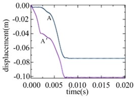
Fig. 5Normal speed response at point A and A’
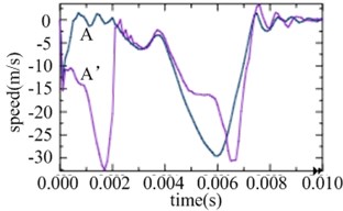
Fig. 6Deformations and stress distributions of the cylinder at each instant along ox-z section
a) Instant at 1 ms

b) Instant at 3 ms

c) Instant at 4 ms

d) Instant at 5 ms

e) Instant at 6 ms

f) Instant at 7 ms
Fig. 7Deformations and stress distributions of the cylinder at each instant along ox-y section
a) Instant at 1 ms

b) Instant at 3 ms

c) Instant at 4 ms
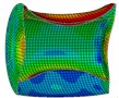
d) Instant at 5 ms

e) Instant at 6 ms
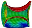
f) Instant at 7 ms
Fig. 8Vertical velocity field of the inner water at each instant along ox-y section
a) Instant at 1 ms

b) Instant at 3 ms
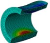
c) Instant at 4 ms

d) Instant at 5 ms
e) Instant at 6 ms
f) Instant at 7 ms
From the normal speed response at point A and A’ shown in Fig. 5 we can find that the inner shell still has good anti-deform ability in the initial stage before the appearance of the bidirectional high-velocity jet, while with the loss of the circumferential stability caused by the jet, the deformation speed ascends rapidly, as well as the deformation amplitude.
4.2. The influence of the outer shell’s thickness
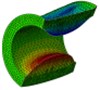
With other conditions invariant, simulative calculations were executed to the cylinders with thickness 2 mm, 2.5 mm, 3 mm and 3.5 mm respectively using the acoustic-solid coupling algorithm in ABAQUS, and the whole calculation time was also 20 ms for each model. The final deformations of the model with different outer thickness are shown in Fig. 9. When the thickness of the outer shell is small, the deformation mode of the inner shell of the double-shell cylinder was similar with that of the single-shell one, and large local inward deformation just appeared on the front side, but the amplitude was much larger (Fig. 9(a-c)). While with the increase of the outer shell’s thickness, obvious difference on the deformation mode between the inner shell of the double-shell cylinder and the single-shell one, and not only on the front side, but on the back side there appeared large local inward deformation (Fig. 9(d-f)), which indicated that the thickness of the outer shell has great influence on the deformation mode of the inner shell.
Fig. 9Final deformations of the model with different outer thickness

a) Width 2 mm

b) Width 2.2 mm

c) Width 2.4 mm

d) With 2.5 mm

e) Width 3 mm
f) Width 3.5 mm
As is shown in Fig. 9, compared with the single-shell cylinder, the deformation of the double-shell one’s inner shell was much heavier, this is because the outside water tank increased the projection area of the explosion to the cylinder on the front side, which means that the cylinder was subjected to more impact energy, and meanwhile, the local high-velocity jet of the inner water took great threat to the circumferential stability of the cylinder. The velocity field of the inner water of the model with outer thickness to be 2 mm at each instant was analyzed, as is shown in Fig. 10, the high-velocity jet was firstly generated on the front side, and then spread sideways. At instant 5 ms, the high-velocity jet was subsequently generated on the lateral surface, while there wasn’t high-velocity jet which can cause large local inward deformation on the back side. These results gave further indication that the local jet effect of the inner water is one of the most important factors to cause the difference of large local deformation between double-shell and single-shell cylinders.
Fig. 10Velocity field of the inner water of the model with outer thickness to be 2 mm at each instant
a) Instant at 1 ms
b) Instant at 2 ms
c) Instant at 3 ms
d) Instant at 4 ms
e) Instant at 5 ms
f) Instant at 6 ms
5. Conclusions
In this paper, a series of simulative studies on the cylinders subjected to underwater explosion were presented using coupled acoustic-structural analysis in ABAQUS, and the different deformation features between the double-shell cylinder and the single-shell one were analyzed, as well as the reason to cause the difference and the influence of the outside water tank on it. The main conclusions are as follows.
1) With the impact of the near-field underwater explosion, large inward local deformation occurred on the impacted side of the cylinder, but no obvious plastic deformation occurred in the parts not covered by the spherical projection of the explosion to the cylinder. With the loss of local dynamic stability of the cylinder, a plastic hinge was generated near the boundary of the spherical projection of the explosion to the cylinder with an approximate elliptic type, whose center is the nearest point on the cylinder to the explosion.
2) With the existence of the outside water tank, the large local deformation feature of the double-shell cylinder becomes different form that of the single-shell one with the same size. From one aspect, the outside water tank increases the projection area of the explosion to the cylinder on the front side, which means that the cylinder will be subjected to more impact energy enough to cause much heavier deformation to the double-shell cylinder. From another aspect, the local jet effect of the inner water is one of the most important factors to cause the different features, because that with the increase of the outer shell’s thickness, the local high-velocity jet of the inner water generated on the back side may take great damage to the circumferential stability of the cylinder, which will cause large local inward deformation both on the impacted side and the back side of the cylinder.
References
-
S. W. Kirkpatrick and B. S. Holmes, “Structural response of thin cylindrical shells subjected to impulsive external loads,” AIAA Journal, Vol. 26, No. 1, pp. 96–103, Jan. 1988, https://doi.org/10.2514/3.9856
-
N. Jones, S. E. Birch, and R. S. Zhu, “An experimental study on the lateral impact of fully clamped mild steel pipes,” Proceedings of the Institution of Mechanical Engineers, Part E: Journal of Process Mechanical Engineering, Vol. 206, pp. 111–127, 1992, https://doi.org/0.1243/pime_proc_1992_206_207_02
-
T. Wierzbicki and M. S. Hoo Fatt, “Damage assessment of cylinders due to impact and explosive loading,” International Journal of Impact Engineering, Vol. 13, No. 2, pp. 215–241, Jan. 1993, https://doi.org/10.1016/0734-743x(93)90094-n
-
J. B. Hu, Z. H. Zhang, and Q. M. Li, “Damage evaluation for an underwater target under underwater explosion,” Journal of Vibration and Shock, Vol. 29, No. 10, pp. 206–210, 2010.
-
X. L. Yao, A. M. Zhang, and W. J. Xu, “Application of coupled acoustic-structural analysis to warship underwater explosion,” Journal of Harbin Engineering University, Vol. 26, No. 6, pp. 707–712, 2005.
-
Z. Z. Shao, “Pressure field distribution around cylindrical shell subjected to underwater explosion,” Journal of Weapon Equipment Engineering, Vol. 38, No. 3, pp. 38–41, 2017.
-
F.-Y. Gao, Y. Long, C. Ji, and L. Lu, “Test for dynamic buckling modes of a metallic cylindrical shell subjected to lateral explosion,” Zhendong yu Chongji/Journal of Vibration and Shock, Vol. 32, No. 24, pp. 117–121, Jan. 2013.
-
J. H. Yuan, X. Zhu, and Z. H. Zhang, “Dynamic bulking of a ring-stiffened cylindrical shell subjected to underwater explosive loading,” Explosion and Shock Waves, Vol. 32, No. 6, pp. 585–591, 2012.
-
C. Ji, Q. J. Xu, W. Q. Wan, F. Y. Gao, and K. J. Song, “Dynamic response of steel cylindrical shells under lateral explosion loading,” Explosion and Shock Waves, Vol. 32, No. 6, pp. 585–591, 2012.
-
A.-M. Zhang and X.-L. Yao, “Interaction of underwater explosion bubble with complex elastic-plastic structure,” Applied Mathematics and Mechanics, Vol. 29, No. 1, pp. 89–100, Jan. 2008, https://doi.org/10.1007/s10483-008-0111-z
-
Y. L. Liu, Z. L. Tian, and A. M. Zhang, “Damage of cylindrical shell structure subjected to underwater explosion loading,” Journal of Vibration and Shock, Vol. 33, No. 22, pp. 178–182, 2014.
-
Z. Zong, Y. J. Zhao, and L. Zou, Numerical Calculation on Damage of Structures Subjected to Underwater Explosion. Beijing: Science Press, 2014.
About this article

The authors would like to acknowledge the support of the 13th Five-Year Plan Fund of China (2019HJHS26). The presented research results are not classified.
